Apple Cinema HD Display 30″ Teardown
Duration: 45 minutes
Steps: 11 Steps
This guide has been refreshed with a fresh translation and is now part of the latest repair guide collection. If you want to see the old version (in its original language), you can find it here.
Step 1


You don’t need to stress about grabbing that specific ’64 Bit Driver Kit’ I mentioned—any good ol’ screwdriver kit with Torx bits will do just fine!
And hey, that ratchet in the pictures? Totally optional, so no worries there!
– Gather up your tools from the teardown list—everything you need is here.
– Place the Cinema Display face down on a soft, cushy surface to keep that precious LCD panel from getting scratched or nicked.
Tools Used

Step 2


A ratchet could come in handy here, but don’t sweat it if you don’t have one.
– Time to get those screws out! Grab your trusty screwdriver and unscrew the two screws located on the sides of the stand where it connects to the display. You’ve got this!
– Image 3: Screws remain.
Step 3


– Grab your Torx driver and unscrew the four screws holding the stand to your display. Don’t lose them—they love to roll away!
– Lift off the stand and set it aside.
Step 4

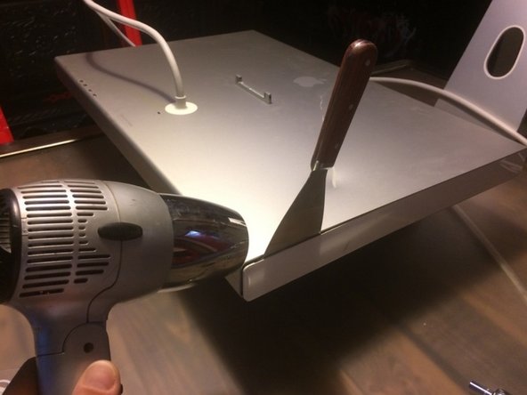
– Gently slide a putty knife into the plastic side piece – but don’t rush into prying it off just yet!
– Give the plastic piece a little warmth by using a heat gun for about 30 seconds, or if you don’t have one handy, a hair dryer for up to a minute should do the trick.
– Now, with care, work the plastic side piece off using your putty knife. If it’s still being stubborn, don’t hesitate to reheat it and try again.
Tools Used


Step 5


Be gentle when prying off this side panel. Keep the putty knife away from the buttons to avoid slicing through the button board cable underneath the plastic. Take your time and work carefully—patience is key! If you need help, you can always schedule a repair.
– Now, go ahead and repeat the steps from Step 4. You’ve got this, keep at it!
Tools Used
Step 6


– Unscrew those four Torx screws – it’s time to get things moving!
– Grab your trusty pry tool and gently pop off the secondary side panel. You’ve got this!
Step 7

Make sure the screws match the length and position of those on the right side panel—keeping everything aligned for a smooth reassembly.
– Now, go ahead and repeat Step 6 for the left secondary side panel. Easy, right?
Step 8

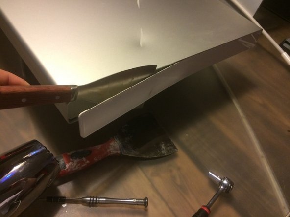
– Gently slide the putty knife between the metal pieces (check out the arrow in the image for guidance).
– Carefully nudge the metal piece highlighted in green towards the display panel to pop that clip free.
– Now, give some love to the identical clip on the other side of the display and repeat the same move.
Tools Used
Step 9

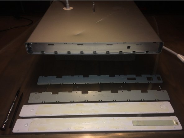
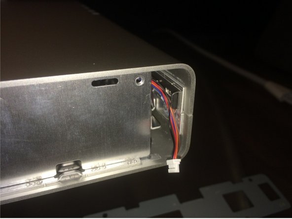
– First image: Gently detach the metal casing at the bottom. If the clips are being a bit stubborn, grab your prying tools and give them a little nudge.
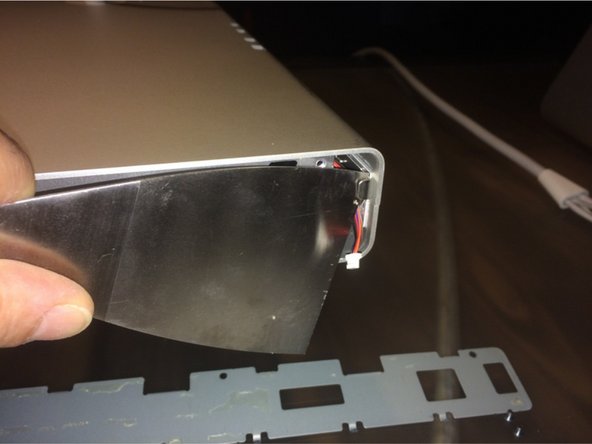
– Second image: Carefully pull the all-in-one cable through the hole in the metal casing. No need to rush here, just make sure it slides out smoothly.
Step 10


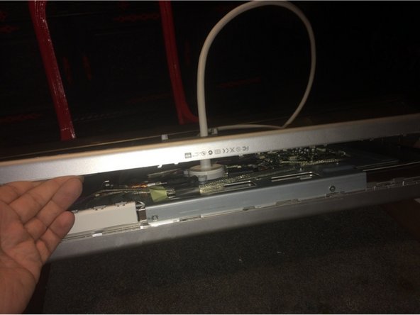
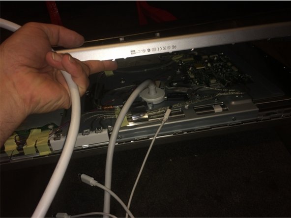
Pro tip: Grab a buddy—one of you can gently keep the enclosure pieces separated while the other lifts out the display panel assembly. Teamwork makes this a breeze!
– Gently peel back the tape marked with the red circle. Next, lift the rest of the component away from the enclosure.
– Heads up: You’ll need to flex the enclosure just a bit to slide the display panel assembly out.
Step 11


– Unscrew the 3 red-circled screws that are keeping the all-in-one cable locked in place.
– Next, tackle the trio of blue-circled screws—don’t let them slow you down.
– Finally, take out the 5 yellow-circled screws holding the logic board steady. You’re really getting somewhere now!
Success!