Asus VivoTab RT TF600T Motherboard Replacement
Duration: 45 minutes
Steps: 14 Steps
Ready to swap out the motherboard on your Asus VivoTab RT TF600T? No worries! We’ve got you covered with this easy-to-follow, step-by-step guide. Let’s dive in and get that tablet back in action. If things get tricky or you need an extra hand, you can always schedule a repair. Let’s get started!
Step 1


Make sure your tablet is powered off before diving in.
– Unplug your tablet from the keyboard base.
– To pop the keyboard off, press the switch on the left side of the screen and lift the tablet away. That’s it—no wrestling required!
Step 2


– Flip the device upside down, grab a PH000 screwdriver, and loosen those two 1.59 mm screws at the bottom. Keep going, you’re doing great!
Step 3


– Take your trusty plastic opening tool and slide it into the bottom right corner—gently now, no need to rush.
– As the screen starts to lift away from the device, work your way around the edges with the tool until the whole screen pops off. Slow and steady wins the race!
Step 4

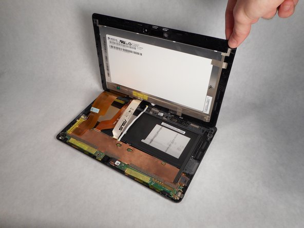
Since the screen assembly is still hooked up to the motherboard, grab a sturdy stack of books or another firm object to prop it up. This way, you can keep working on freeing those cables without the screen collapsing on you.
– With the frame now separated, gently lift the screen assembly just enough to give the motherboard some breathing room. You’ve got this!
Step 5

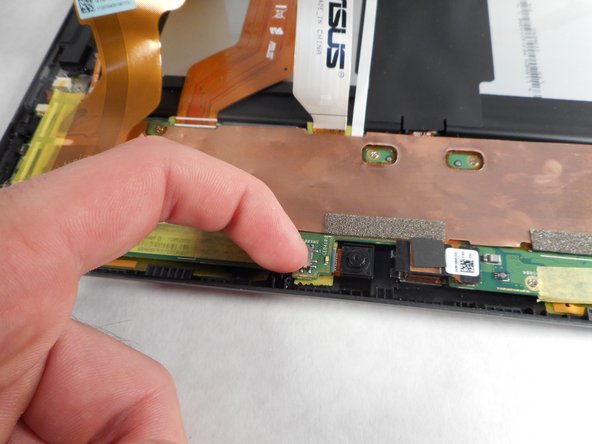
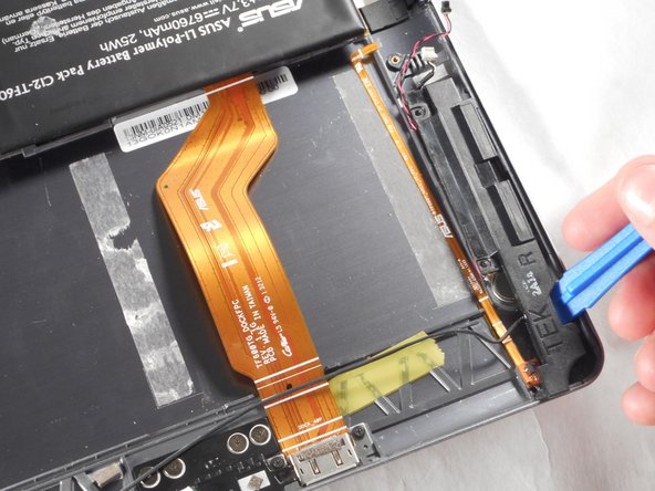
Heads up! The battery hooks right into the motherboard, so for safety, flip that DIP switch to OFF before you go any further. No one wants an accidental mini light show!
– Before you start disconnecting those display cables, make sure to flip off the DIP switch. This little switch is your best friend, as it cuts the power to the system so you don’t get any surprises!
Step 6
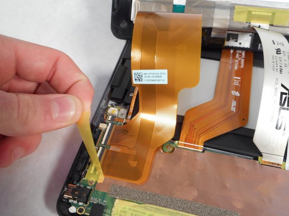

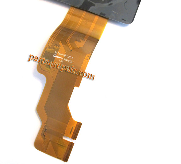
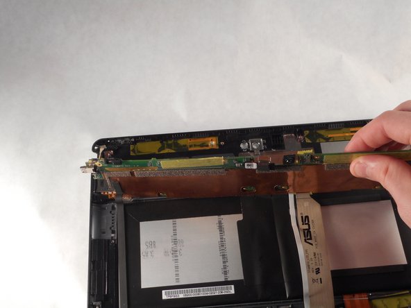
– Peel off the yellow tape holding the digitizer and LCD screen ZIF connectors in place.
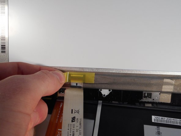
Step 7

– Once the yellow tape is peeled back, grab a plastic opening tool and gently lift up the two ZIF connector tabs holding the digitizer ribbon cable. Carefully pull the ribbon cable free to disconnect it. If you need help along the way, you can always schedule a repair.
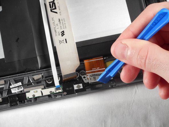
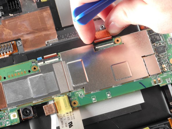
Step 8

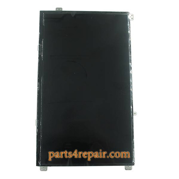
– Grab a plastic opening tool and gently lift the LCD screen’s ZIF connector; carefully pull the ribbon cable free.
Step 9

– Gently lift the screen upwards to release it from its position.
Step 10

– Grab your Phillips #00 screwdriver and carefully unscrew the pair of 0.79mm screws securing the charging port. You’re doing great—keep it up!
Tools Used

Step 11

– Let’s get started by placing the plastic opening tool right behind the charging port – position it near the outer edge of your device for the best results.
– Now, carefully pry the charging port away from the frame, taking your time to ensure you don’t damage anything.
Step 12


– Take out the eleven 0.79 mm PH000 screws securing the motherboard. Keep those tiny screws safe—they love to hide!
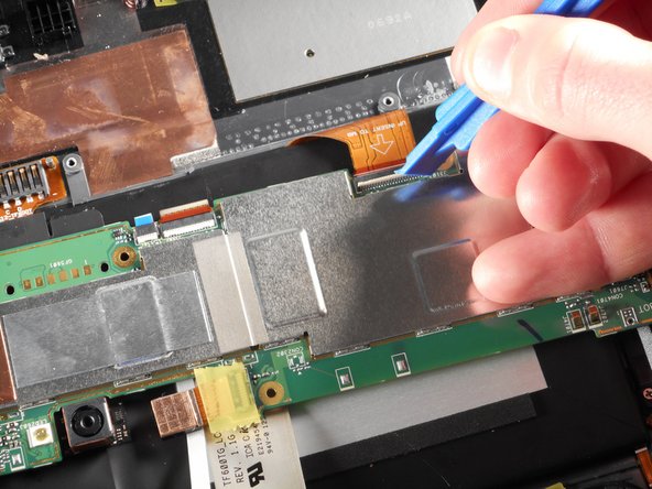
Step 13

– Gently work a nylon spudger around the edges to ease the motherboard away from the back panel—think of it like coaxing a stubborn suitcase zipper.
– Once the motherboard is free from the sticky stuff, use your hand to lift it up and over to the other side of the back panel. Slow and steady wins this round!
Step 14

– Grab a plastic opening tool and gently lift the battery ZIF connector to disconnect it; then carefully peel back the ribbon cable.
– Take out the motherboard to continue with the repair.
Success!