ASUS Zen Pad 10 Micro USB Port & Camera Replacement
Duration: 45 minutes
Steps: 12 Steps
I wouldn’t recommend this repair for those just starting out.
The USB port is your go-to spot for charging and transferring all that juicy data, so it needs to be in tip-top shape! These micro USB ports are a bit delicate, so we’ve got a handy fix for this particular tablet. Just a heads up: you’ll be working with some tiny copper pads—less than 1mm wide! So, if you’re not super confident with your soldering skills, you might want to sit this one out. On the flip side, replacing the camera is a breeze and totally doable for anyone! Be sure to read through the entire guide before diving in, and double-check that your replacement part is the right fit for your tablet. If you need help, you can always schedule a repair.
Step 1


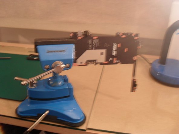
– First things first, make sure your tablet is powered down completely—no sneaky sleep mode! Grab your trusty spudger and gently slide it in between the screen and the plastic back to get things rolling.
– Look for the arrow pointing you in the right direction for spudger placement. That’s your cue to pry the plastic back away from the screen—let’s get that case off!
– Don’t go overboard with the pressure; a little leverage is all you need to pop it open. If you’re wrestling with it, you might be doing it wrong, and we definitely don’t want any damage happening here.
Tools Used

Step 2


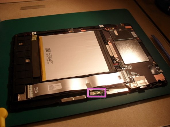
– The battery hogs most of the space here, with the motherboard chilling over on the right. Screws are marked in red, and green arrows are your guide to removing connectors. Easy peasy!
– Before diving in, take a moment to gear up with anti-static precautions and rock those nitrile gloves like a pro. Safety first, stylish second!
– The golden rule: disconnect the battery connector before doing *anything* else. Seriously, make this your first move—check the next step for details.
Step 3

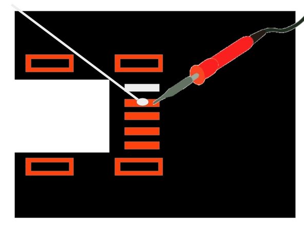
– Let’s get started. Use a plastic spudger to carefully lever the connector marked at 1 up and in the direction of the arrow. Remember to remove power to the device before you begin – it’s crucial to avoid any shorts that could damage your device. And don’t forget, a plastic spudger is a must for this step, so make sure you’re using the right tool.
– Now that the battery connector is out of the way, it’s time to remove the screen at 2. Use your trusty spudger to lift up the white plastic lip marked with the red dot, and then you should be able to pull the ribbon cable out of the connector.
– If your device has tape holding the motherboard to the battery, you’ll need to remove it. Use a pair of tweezers to gently pick up the edge of the tape and then peel it off. If you’re having trouble or feel unsure about any part of the process, don’t worry – you can always schedule a repair with Salvation Repair for some extra help.

Step 4

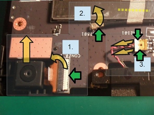

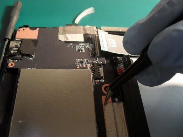
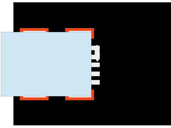
– Time to get those modules out. They’re hanging out right here. If it’s just the camera you’re swapping, you’re off the hook for the rest of the modules—focus on removing that.
– 1. Grab your spudger (look for the green arrow indicator) and slide it gently under the connector. Lift the connector up and toward the camera. Once lifted, the ribbon cable will practically jump out. To remove the camera, lift it up using your fingernails or tweezers. Swap the camera and rebuild your device—if that’s all you’re doing, you’re golden!
– 2. Check for fabric tape on the Wi-Fi cable. If you see some, carefully unpeel it or cut it off. Next, use the spudger to pop the connector UP. Whatever you do, don’t tug at the cable—apply leverage to the connector and lift it straight off the board.
– 3. Take your spudger and gently work the connector out by pushing against its corners. Alternate sides and apply just enough pressure to get it to budge—it doesn’t need Hulk-level strength! Once you’ve removed both module connectors (check the last picture, green ring markers) and unscrewed the screws marked red, the modules will come right out with no fuss.
– Pro tip: Use a marker pen to label the top side of your cable connectors—it’ll save you from guessing their orientation when you’re reassembling!
Step 5

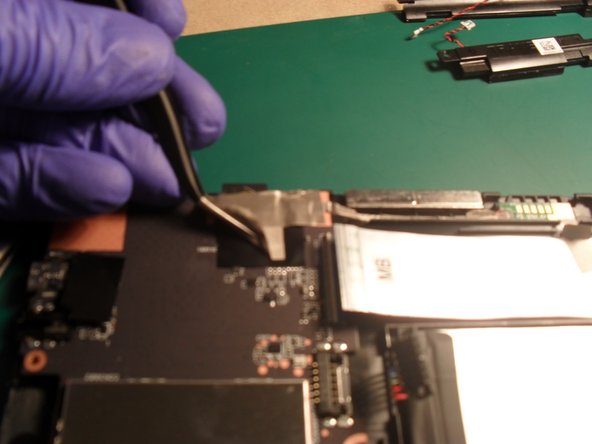
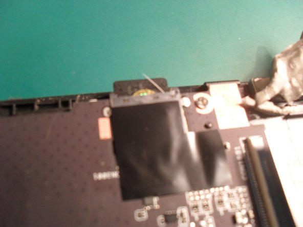
– First, let’s get that tape out of the way. Gently peel back the tape at the top to expose a sneaky hidden screw. Don’t forget to keep an eye on the underside of the board, where you’ll find another connector that needs some TLC.
– Now it’s time to bust out the tweezers. Carefully peel back the tape, and if it’s connected to the cable under the board, just snip it (but make sure you don’t accidentally cut the cable – we don’t want any casualties!).
– Next, remove all the screws, and you’ll be ready to pull out the motherboard. Easy peasy!
Tools Used
Step 6


– With the board facing you as shown in the image, gently lift the motherboard from the back and tilt it towards yourself, like flipping it over the front edge.
– Now that you’ve got it angled right, you can easily access the connector and disconnect it, just like you did with the battery connector. This will free the board from the device.
Step 7


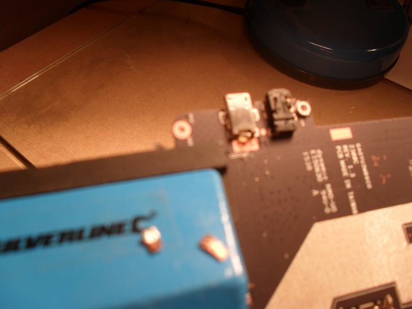
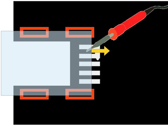
– Alright, let’s get started! On the top of the board, you’ll find the USB connector held on by four pins marked in red. If you spot a sticker on the port, gently peel it off using tweezers. Now, look for the yellow markings – they indicate five pins that need a little love with the soldering iron before we can say goodbye to the port using the hot air gun.
– Flip that board over and it’s time to protect our tiny components! Grab some heat-proof tape and cover those little guys. This will prevent any unfortunate surprises when the hot air comes into play.
– Oh, and don’t forget about the neighboring jack socket! Wrap it up with heat-proof tape (it’s marked in green) to keep it safe from melting away. It’s a great idea to tape down the jack sockets on both sides of the board. Cut the tape to fit snugly around the components and jack socket to keep everything intact while you work your magic!
Tools Used
Step 8
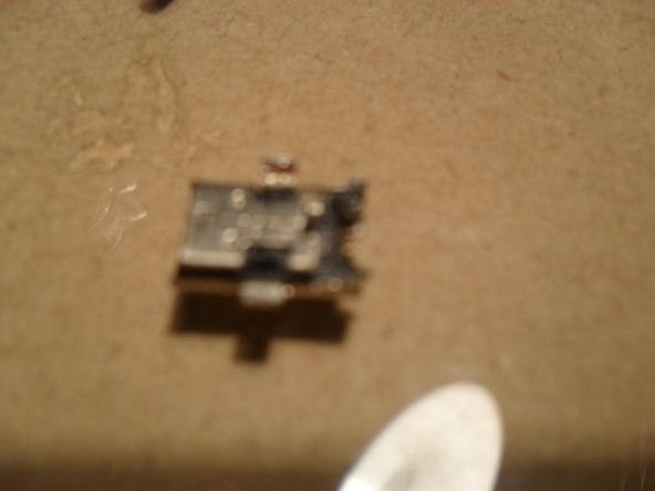

– Check out the back, where you’ll find the connections—look for those five tiny pads that need to be desoldered. Clean them up real good to make the removal process a breeze!
– After you’ve scrubbed off as much solder as possible, grab that hot air gun and crank it up to 450C on full blast. Let it work its magic to heat the component, and when it’s hot enough, use tweezers to lift it right off!
– Sure, you could try this without a hot air gun, but let’s be real—the melting point of that solder is high, and it’s a multilayer board. This is one of those times when having the right tools makes life a lot easier. Just be ready for the heat to drop when you’re swapping out tools.
– Now, let’s tidy up! Use solder braid with a good amount of flux to soak up the extra solder around those lugs. Then, grab some cotton buds and acetone to clean off the leftover flux. Just make sure no stray cotton hangs around, as that could lead to some unwanted shorts!
– With your trusty soldering iron and a healthy dose of flux, take that desoldering braid and soak up all the solder you can. It might take a little time, but hang in there—it’ll make things smoother for the next steps. And remember to snip the used braid, feeding in a fresh piece each time with more flux.
– When you’re melting the solder around those four mounting pins, don’t forget to heat up the five pads you cleaned earlier. This keeps the copper pads intact while helping that USB port come right out. It should lift away easily with tweezers, so no need to force it! And keep your fingers away from the port; it’s hot, and we don’t want any burns!
– Feel free to use the soldering iron for a bit of extra heat on those pins to speed things up! Oh, and remember to cover the nearby plastic audio jack socket with heat-proof tape, just like we talked about before.
Tools Used


Step 9

– Let’s get started. To give you a better idea of the tiny components we’re working with, think of it like this: the parts are about the size of your little finger.
– First, swap out the chisel tip on your soldering iron for the conical tip. Make sure it’s cooled down and the power is off. This will give you the precision you need for this delicate job.
– 1. Apply a tiny amount of solder to the copper terminal pads by heating the end of the trace. This is where the magic happens.
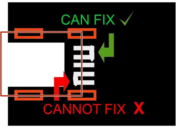
– 2. Don’t stress if you accidentally create a bridge between the tracks – it’s an easy fix. However, if it happens at the hidden end (the part that will be covered by the port hood), you’ll need to remove it. Take a look at the third picture to see the port position marked in red.
– 3. Take a closer look with a magnifier or jeweller’s loupe to ensure there’s no solder splash or bridges between the terminals at the hidden end. If you find any, you can remove them. And if you’re feeling stuck, remember: it’s all part of the process.
Tools Used
Step 10
– Grab the replacement USB port with tweezers and hold it steady. Use the hot air gun to gently heat the traces and pins until the solder melts and bonds beautifully. Keep it flat—no angles, or you might create a pad-bridging masterpiece (not the good kind).
– No one likes bridges here, so aim for clean connections. If you slip up, grab your soldering iron and glide it out along the traces. Seriously, don’t drag the solder toward the port—it’s an express ticket to component doom. Let the surface tension work its magic, pulling the solder onto its destined pad while eliminating any pesky bridges. Stay cool—you’re doing great!
– Once you’re happy with your work, take a good look. If it’s solid, go ahead and solder the 4 mounting pins. Switching back to a chisel tip on your iron can make this part a bit easier if that’s your jam.
– This step’s a tricky one, but don’t stress. If things go sideways or you bridge the pads, just heat the port with the air gun, remove it, clean things up, and give step 9 another go. A heads-up, though—dragging solder toward the port is a sure way to end the game, and you’ll need a brand-new micro USB port. If you need help, you can always schedule a repair!
Tools Used
Step 11

– If any of the pins are touching each other, you could fry the board—seriously, it’s not a good look. Double-check that there are no shorts before you even think about adding power.
– The smoothest way to handle this is by using a micro USB cable. Grab one you don’t mind sacrificing, snip it in half, and peel back the insulation to reveal those wires. Trying to fit a multimeter probe directly into the port? Yeah, good luck with that—it’s a no-go.
– Here’s the move: clamp one end of the cable with a crocodile clip, hold a probe there, and then use the other probe to check the pad’s resistance. Be laser-focused—one pad, one reading! Oh, and make sure your multimeter is set to the ohm meter mode, not the continuity checker with the beep. That setting can miss some sneaky mistakes.
– A heads up—don’t touch the outer casing of the USB port! It’s connected to the board’s DC and could throw off your readings big time. If you spot a short, go ahead and desolder the port, then give it another shot. It might take a couple of tries to nail it, but persistence pays off!
Tools Used

Step 12

– First, let’s get the motherboard connector and battery connectors securely clipped in. Don’t forget to clip the wifi cable into place too – we need everything snug and cozy in there. And remember, the battery is the last piece of the puzzle, so save it for last.
– Take a peek inside the case and you’ll spot some copper pads sitting on a tiny circuit board. Just make sure that board is still in its original position, nice and tidy.
– Time to put everything back together. Start with the power switch and volume controls – get those aligned just right, and then clip the rest of the case back into place. Easy peasy.