Duration: 45 minutes
Steps: 107 Steps
Take extra care when isolating the battery with a battery blocker to keep things safe and smooth.
Ready to swap out the battery in your iPad 5 Wi-Fi? Take your time when separating the battery with a battery blocker—those contacts are delicate and can be easily harmed, causing permanent damage. If you decide to skip isolating the battery, steer clear of metal tools unless absolutely necessary (like removing screws) to avoid short circuits and protect the sensitive circuits inside.
Step 1

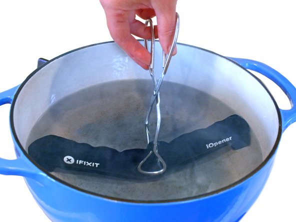
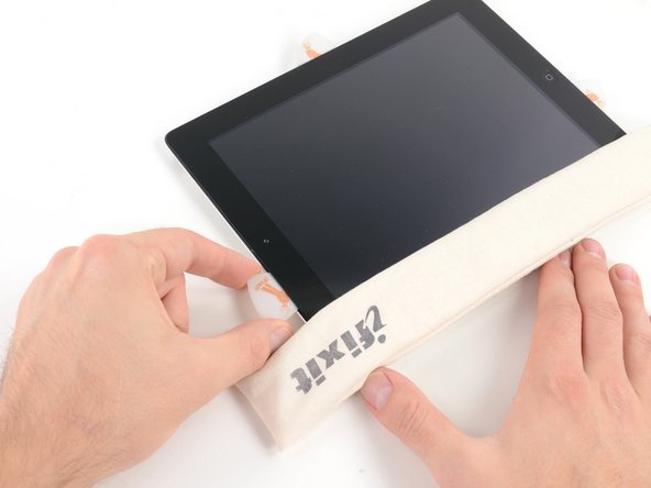
– Warm up an iOpener and press it against the left edge of your device for about two minutes. Let the heat work its magic to soften things up.
Tools Used

Step 2


– While the adhesive is doing its slow-motion dance and loosening up, keep an eye out for these sneaky spots that don’t like being pried:
– Front camera
– Antennas
– Display cables
Step 3


The next three steps show off the Anti-Clamp, our nifty little gadget that makes opening your device a breeze! If you’re not using the Anti-Clamp, just skip ahead three steps for another way to tackle this.
Want to master the Anti-Clamp? Check out this handy guide for all the details!
If your iPad’s surface is feeling a bit too slick for the Anti-Clamp to grip, don’t worry! A little tape can help create the perfect surface for better traction.
– Give that blue handle a little tug back to free the Anti-Clamp’s arms.
– Slide something beneath your iPad so it’s sitting nice and flat between those suction cups.
– Get those suction cups cozy near the center of the left edge—one at the top and one at the bottom.
– Keep a steady hand on the bottom of the Anti-Clamp and press down firmly on the top cup to kick that suction into gear.
Step 4


– Give that blue handle a gentle tug forward to lock those arms in place!
– Now, spin that handle a cool 360 degrees clockwise or until those suction cups start to stretch their muscles.
– Keep an eye on those suction cups and make sure they’re staying in sync. If they start to go their own way, simply loosen them up a bit and guide those arms back into alignment.
Step 5


Take it easy—don’t twist more than half a turn at once, and give it a minute between turns. Let the Anti-Clamp do its thing, and time will handle the rest for you.
For a full breakdown on how to use a hair dryer, check out this handy guide.
If the Anti-Clamp isn’t making the gap you need, just give the area a little more heat and twist the handle clockwise by half a turn. Easy fix!
– Hang tight for a minute to let the adhesive take a breather and create a little opening gap.
– Not feeling enough heat? No problem! A hair dryer can work wonders—just warm up the left edge of the iPad.
– When the Anti-Clamp gives you a nice opening, slide in an opening pick under the digitizer.
– Feel free to skip the next step!
Step 6


If your screen is looking like a spider web, don’t worry! Slapping a layer of clear packing tape on it can help the suction cup stick better. If you’re feeling adventurous, you can also use some really strong tape in place of the suction cup. And if the situation is really dire, a little superglue on the suction cup might just do the trick to keep it in place on that cracked beauty!
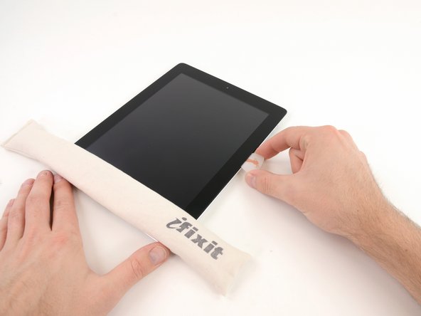
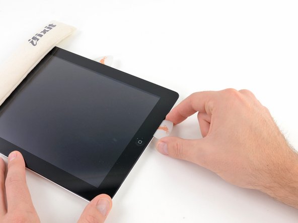
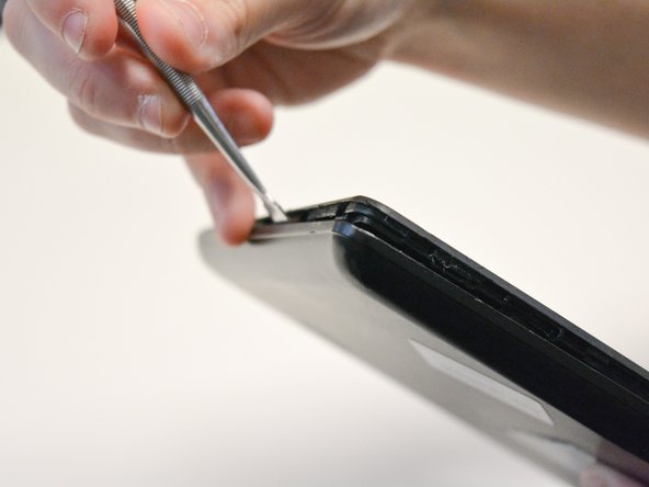
– When the screen feels warm to the touch, stick a suction handle onto the left edge, making sure it’s as close to the edge as you can get.
– Gently lift the screen using the suction handle to create a tiny gap between the digitizer and the frame.
– Slide an opening pick into the gap between the digitizer and the frame to keep things moving.
Tools Used

Step 7


No stress if the opening pick is visible through the digitizer — just slide it right out. The LCD screen should stay safe, but be careful not to leave behind any stubborn adhesive that’s a pain to clean.
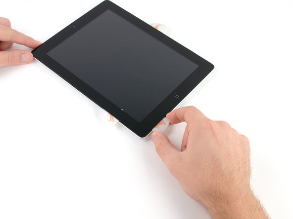
– Slip a second opening pick into the gap you just made.
– Gently slide the pick toward the bottom-left corner to break the adhesive’s grip.
– Leave that pick chilling in the bottom-left corner to keep the adhesive from sealing back up.
Step 8


– If your opening pick gets a little stuck in the adhesive, just give it a gentle ‘roll’ along the side of the iPad to keep peeling away that sticky stuff!
Step 9


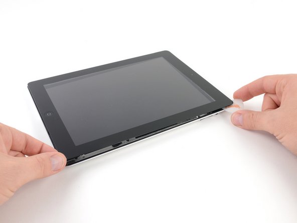
– Gently slide the first opening pick toward the top-left corner of your device to break that sticky bond. You’re doing great!
– Once you’ve got that pick in place, leave it there to keep the adhesive from playing tricks on you again.
Step 10

– Warm up an iOpener and stick it on the top edge of your device for a solid two minutes to loosen things up.
Tools Used
Step 11


– Gently twist the pick around the top-left corner of your device to break that stubborn adhesive free. You’re doing great!
Step 12


Be careful around the front camera when you’re using the pick! It’s easy to accidentally damage the lens. The following steps will guide you through how to avoid that mishap.
– Gently slide the opening pick along the top edge of your device, stopping right before you reach the front camera—smooth moves only!
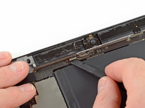
Step 13


– Gently pull the pick until just the tip is nestled between the digitizer and the frame.
– Slide that pick right above the front camera to break free the adhesive holding it down.
– Keep the pick close to the right side of the front camera; you’re doing great, so let’s keep going!
Step 14


– Place the pick back into position and gently slide it toward the top-right corner of the device to completely peel off the top adhesive.
– Leave the pick snugly in the top-right corner so the adhesive doesn’t sneak back into place. You’ve got this!
Step 15

– Warm up your iOpener and give it a cozy two-minute hug on the right edge of the device.
Tools Used
Step 16


– Gently glide the pick around the top-right corner of your device to break the adhesive seal. Take your time and be smooth—it’ll separate like magic.
Step 17


The display cables hang out about halfway up from the bottom of your iPad. Slide carefully and stop once you’re about three inches from the bottom to avoid any surprises.
– Grab a fresh opening pick and slide it right into the middle of the iPad’s right edge like a smooth operator.
Step 18

– Warm up an iOpener and stick it on the bottom edge of your device for a solid two minutes. You’ll be surprised how much this little trick helps!
Tools Used
Step 19


Be careful not to spin the pick all the way around the corner; it could end up causing some trouble for the antenna.
– Gently slide that bottom-left pick into the corner like you’re opening a secret door to success and separate the adhesive with style.
– Keep that pick in place at the bottom-left corner before we dive into the next step—it’s like giving it a little high-five!
Step 20


Just remember to gently slide the pick toward the home button, not away from it! We wouldn’t want to accidentally give that antenna a workout it didn’t sign up for.
If you find yourself needing to slide the pick over this area again, just pop it out and reinsert it at the bottom-left corner. You’ve got this!
– Pop a new opening pick into the gap you just made along the bottom edge of the iPad.
– Gently slide the pick over the antenna, stopping just before you reach the home button.
– Let the pick hang out to the left of the home button before moving on.
Step 21


Be super careful and only slide the pick up to 1 mm—going further could mess with the right antenna. Better safe than sorry!
– Gently slide an opening pick into that little gap you just made.
– Now, carefully maneuver the pick under the home button and glide it towards the bottom-right corner, ensuring that only the tip is nestled between the digitizer and the frame.
Step 22


Be sure to slide the pick gently towards the home button and avoid pushing it away. You wouldn’t want to accidentally give the antenna a little bump, right?
If you need to glide the pick over this spot again, just pull it out and pop it back in at the bottom-right corner to keep things smooth.
– Grab that trusty pick and slide it over towards the home button to help release the bottom adhesive completely.
– Once you’ve done that, leave the pick resting to the right of the home button before moving on to the next step.
Step 23

– Warm up an iOpener and stick it on the right edge of your device for a solid two minutes to get things nice and toasty.
Tools Used
Step 24


Take it slow and steady here! Make sure the adhesive is nice and warm so it’s easy to separate, and carefully work your pick around all the edges. Don’t hesitate to pause and reheat if things get tricky.
If you feel some serious stubbornness, give those edges another warm-up and gently slide your opening pick along to loosen things up.
– Gently twist the two opening picks at the left corners of the iPad to carefully lift the digitizer a bit, breaking up the last bit of adhesive holding it down.
Step 25


– Gently raise the left edge of the digitizer to help loosen the adhesive along the right edge of your iPad. You’re doing great!
Step 26


– Carefully hold the digitizer in place while you slide an opening pick between the two display cables to gently peel apart the last bit of stubborn adhesive.
Step 27


– Once you’ve separated all the adhesive, carefully open the digitizer like a book and lay it flat next to the iPad.
– When you’re putting it back together, take a moment to clean off any leftover adhesive from the frame—and the digitizer if you’re reusing it—with some isopropyl alcohol. Add fresh adhesive with our adhesive strips or pre-cut adhesive cards.
– As you reassemble the device, watch out for the display cables. Make sure they’re neatly tucked underneath the LCD screen to avoid any potential damage.
Step 28


– Peel back any tape that’s hiding the LCD screws so you can get to them.
Step 29

– Time to tackle those Phillips screws holding the LCD in place! Let’s get to it:
– First up, grab three of those 4.0 mm screws and say goodbye to them.
– And don’t forget about that one lone 4.8 mm screw – it’s got to go too!
Step 30


Don’t yank the LCD off just yet—it’s still hanging on by a few cables near the home button. Start lifting gently from the front-facing camera side instead.
Take it slow and steady as you flip the display over, keeping an eye on those delicate LCD cables.
Gently place the LCD on a soft, clean surface that won’t leave any pesky lint behind.
– Grab your trusty spudger and gently wiggle the flat end to nudge the LCD out of its cozy spot just enough so you can grab it with your fingers.
– Now, flip that iPad LCD like you’re turning the pages of a captivating book, lifting it near the camera and pivoting it over the home button end of the rear case.
– Carefully lay the LCD face down to expose those display cables, giving you clear access for the next steps.
Tools Used

Step 31
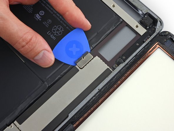

Handle that battery blocker like it’s a delicate dance! The battery contacts are super sensitive and can get damaged easily, leading to some serious trouble. Stay sharp and take your time!
To keep short circuits at bay, consider using a battery blocker or a handy modified opening pick to disconnect that battery.
If you’re finding it tricky to slide the battery blocker under the logic board, a playing card can do the job just as well to disconnect the battery.
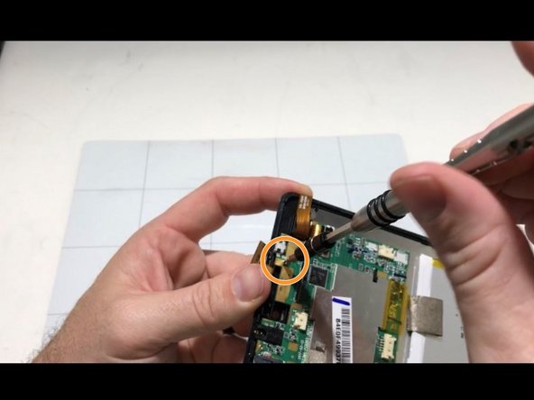
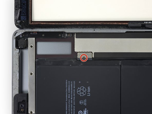
– First things first, grab that trusty 2.3 mm Phillips screwdriver and unscrew the lone screw that’s holding the battery connector snugly to the logic board. It’s like a little secret keeping your battery in place!
– Now, slide that battery blocker right under the battery connector area of the logic board. Let it chill there while you get your hands dirty. You’ve got this!
Tools Used

Step 32

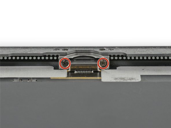
– Unscrew the three 1.4 mm Phillips screws holding down the display cable bracket—time to loosen things up a bit!
Step 33
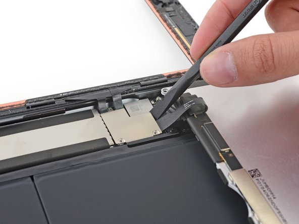
Be careful with the display cable connector! It’s stuck to the underside of the bracket, so when you’re using the spudger, don’t go too deep under there. You wouldn’t want to accidentally give that connector a bad day!
– Carefully slide the flat end of your spudger under the display cable bracket and lift it straight up off the logic board like a pro.
Tools Used
Step 34

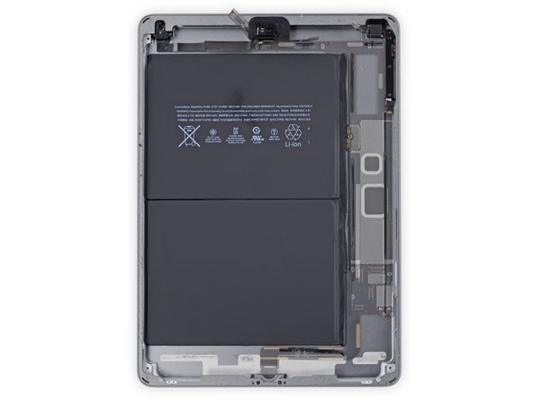
– Carefully pry off the LCD to reveal what’s underneath.
Step 35


– Peel away any tape that’s hiding the home button ribbon cable connector. You’ve got this!
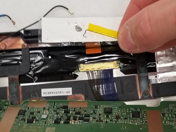
Step 36


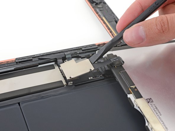
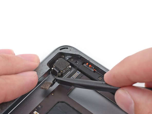
– Grab your trusty spudger and use the flat end to carefully lift the tab on the home button ribbon cable ZIF connector. Just give it a gentle nudge upwards.
– Now, with a little finesse, slide the home button ribbon cable out of the ZIF connector. A smooth, horizontal pull should do the trick!
Tools Used
Step 37


Be gentle! Pry only on the connectors themselves, not the socket on the logic board. A little care goes a long way!
– Take the flat end of a spudger (or your trusty fingernail) and gently lift those two digitizer cable connectors straight up from their sockets. No need to rush, just be careful and give them a little wiggle if needed. Easy peasy!
Tools Used
Step 38


– Gently lift the home button ribbon cable away from the sticky stuff holding it down to the back case—nice and easy, you got this!
Step 39


The insulation is a bit of a sneaky character—it’s not something you can spot with the naked eye! Unlike the foam dust barrier strips you might find on many iPads, this insulation has its own unique vibe.
– First up, let’s get that front panel assembly off. It’s time to say goodbye to the old!
– When you’re putting everything back together, make sure to give the inside of the front panel a little TLC by wiping away any dust or fingerprints. A clean display is a happy display!
– If your new display starts to act a little quirky with ‘ghost’ or ‘phantom’ touches, don’t fret! Just grab some very thin insulating tape, like Kapton (polyimide) tape, and add a layer to the highlighted areas on the back of the panel. The panels from Salvation Repair come prepped with the right insulation, so you might not even need the tape!
– Remember, without the right insulation, those areas of the digitizer can misbehave and create grounding issues with other components, leading to touch input problems. But you’re on top of this!
Step 40


– Grab a spudger and carefully slide it under the antenna cable near the edge of your iPad. Gently lift it up to disconnect the antenna cable. It’s like giving your iPad a little ‘untangle’ moment.
Tools Used
Step 41


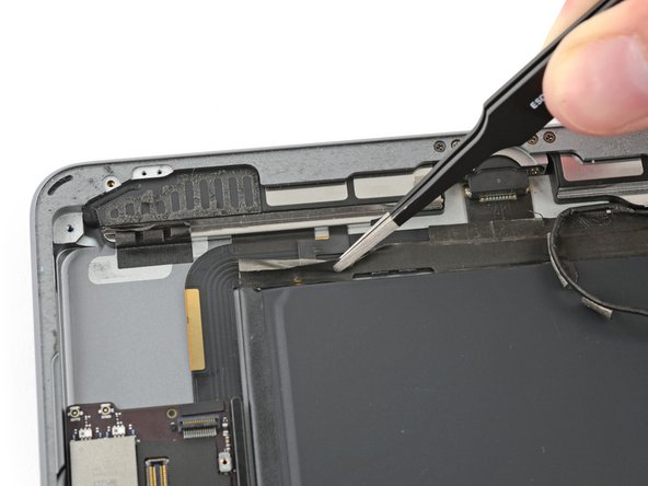
– You’ve got two big strips of tape holding the right antenna cable snugly to the back case. Let’s get that tape off!
– Gently peel the tape away from the rear case.
– As you pull up the antenna tape, keep it attached to the antenna cable. This little trick will make reassembly a breeze!
Step 42


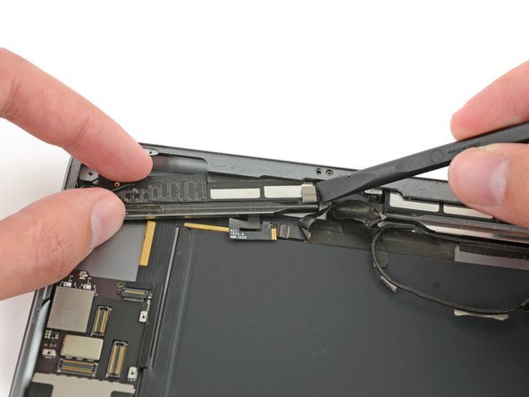
The antenna cable is held in place on the speaker by a tiny metal bracket. This little guy is permanently crimped to the antenna and glued right onto the speaker’s enclosure, keeping everything snug and secure.
– Gently slide an opening pick between the speaker enclosure and the antenna cable bracket—easy does it!
– Now, move the pick towards the home button to slice through that adhesive like a pro.
– Push the bracket away from the speaker until it’s clear of the tape beneath—you’re almost there!
Step 43

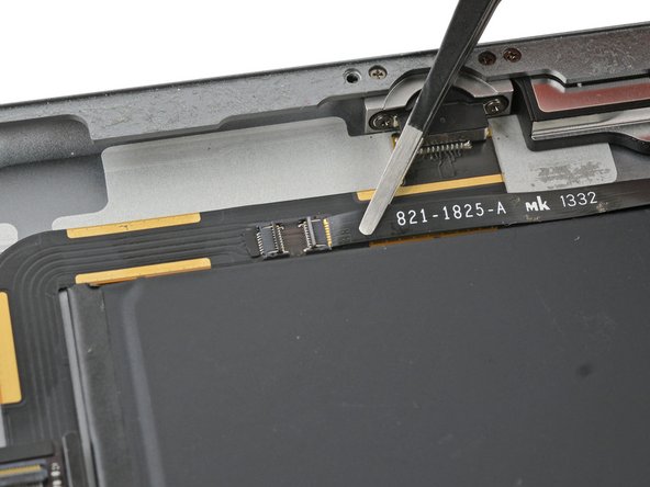
– Grab your Phillips #000 screwdriver and loosen these screws holding down the right antenna:
– One 2.3 mm screw
– Two 1.4 mm screws
Step 44


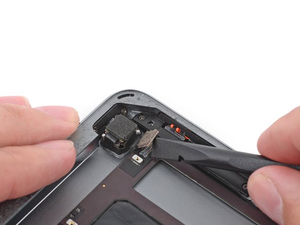
– Gently slide the flat end of a spudger between the antenna and the speaker assembly. You’ve got this!
– Carefully glide the spudger towards the home button to slice through the foam adhesive that’s holding the antenna in place. Easy peasy!
Tools Used
Step 45

– Take off the right antenna from the iPad.
Step 46


– Slide a spudger under the left antenna cable and gently lift it up to detach the antenna cable connector.
Tools Used
Step 47


– You’ve got five pieces of tape giving the left antenna cable a cozy hug over the right speaker cable connector. Time to peel that tape away from the rear case!
– Gently fold the antenna cable aside so it doesn’t get in your way.
Step 48

If the speaker cable has a little bend, it might make peeling that tape off a bit tricky. Just take your time with it.
When using tweezers, be gentle! Focus on just grabbing and peeling the tape, leaving the cable beneath safe and sound.
– Grab the tape just below the speaker and gently peel it downward, moving away from the edge of the case.
Tools Used

Step 49


– Gently peel the tape back toward the home button to reveal the speaker cable connector underneath.
Step 50


– Gently use the pointed tip of a spudger to lift up the little retaining flap on the right speaker cable connector.
– Carefully slide the speaker cable straight out from its ZIF connector, like you’re easing it out of a snug parking spot.
Tools Used
Step 51


– Peel away the tape that’s keeping the speaker snug against the rear case.
Step 52


– Gently lift the LCD buffer tape away from the rear case—take your time and keep it chill.
Step 53

– Loosen up that 2.2 mm Phillips #000 screw holding the speaker to the rear case and set it aside. You’re getting closer!
Step 54


– Gently slide your fingernail or the flat end of a spudger into the groove of the speaker housing, right near the corner of the rear case.
– Now, give the speaker a little tug, pulling it down and away from that corner of the case.
Tools Used
Step 55


– Grab your trusty spudger and gently nudge the speaker out from its cozy spot beneath the rear case. You’ve got this!
– Now, go ahead and carefully lift the right speaker out of the iPad. You’re on a roll!
Tools Used
Step 56

– Grab your Phillips #000 screwdriver and unscrew the three 1.4 mm screws holding the upper component cable bracket in place. Once they’re out, you’re one step closer to the magic!
Step 57

If your iPad is the Wi-Fi/Cellular version, get ready for a little twist! It’ll have a different look and you’ll need to unscrew two extra screws to get to those hidden components under this bracket. You’ve got this!
– Take off the upper component cable bracket with a dash of finesse!
Step 58


– There are still two pieces of tape holding the left antenna cable to the back case.
– Carefully peel the tape off from the rear case.
Step 59


– Gently slide an opening pick between the speaker enclosure and the antenna cable bracket.
– Glide the pick towards the home button to break that pesky adhesive seal.
– Carefully nudge the bracket away from the speaker until it’s free from the tape below.
Step 60

– Time to unscrew! Let’s find those Phillips #000 screws and get to work:
– First up, grab two of those tiny 1.4 mm screws.
– And don’t forget about that lone 2.3 mm screw waiting for its turn!
Step 61


– Gently slip the flat end of your spudger between the antenna and speaker assembly. No rush—take your time here!
– Now, carefully slide the spudger towards the home button to slice through the foam adhesive holding the antenna in place. Easy does it!
Tools Used
Step 62

– Detach the left antenna from your iPad with care.
Step 63


– Peel off the tape that’s keeping the left speaker cable connector nice and cozy.
Step 64


– Gently use the pointy end of your spudger to lift up the little flap holding the left speaker cable connector in place.
Tools Used
Step 65

– Gently slide the speaker cable straight out of its ZIF connector—easy does it!
Step 66


– Peel off the tape that’s keeping the speaker snug against the rear case. You’ve got this!
Step 67

– Let’s get that speaker out! Start by unscrewing the 2.2 mm Phillips #000 screw that’s holding it snugly to the rear case.
Step 68


– Carefully lift the left speaker ribbon cable so it can gracefully dodge the battery as you slide the speaker enclosure out.
Step 69


– Slide your fingernail or the flat end of a spudger into the groove on the speaker housing near the rear case corner.
– Gently pull the speaker downward, away from the case corner.
Tools Used
Step 70


– Grab a spudger and gently pry the speaker out from under the edge of the rear case—think of it as a tiny lever doing the heavy lifting.
– Carefully lift the left speaker out of the iPad, making sure not to rush the move.
Tools Used
Step 71


Gently pry up on the connector only—avoid tugging on the socket itself to keep things safe and sound.
– Grab your trusty spudger and gently use the flat end to disconnect the front-facing camera connector from the logic board. Easy peasy!
– Now, fold the front-facing camera cable out of the way like it’s saying, ‘Catch you later!’
– You’ll notice a little bit of conductive adhesive hanging out between the gold-colored cable contacts. Just make sure to give it a good press during reassembly to keep those contacts happy and in place.
Tools Used
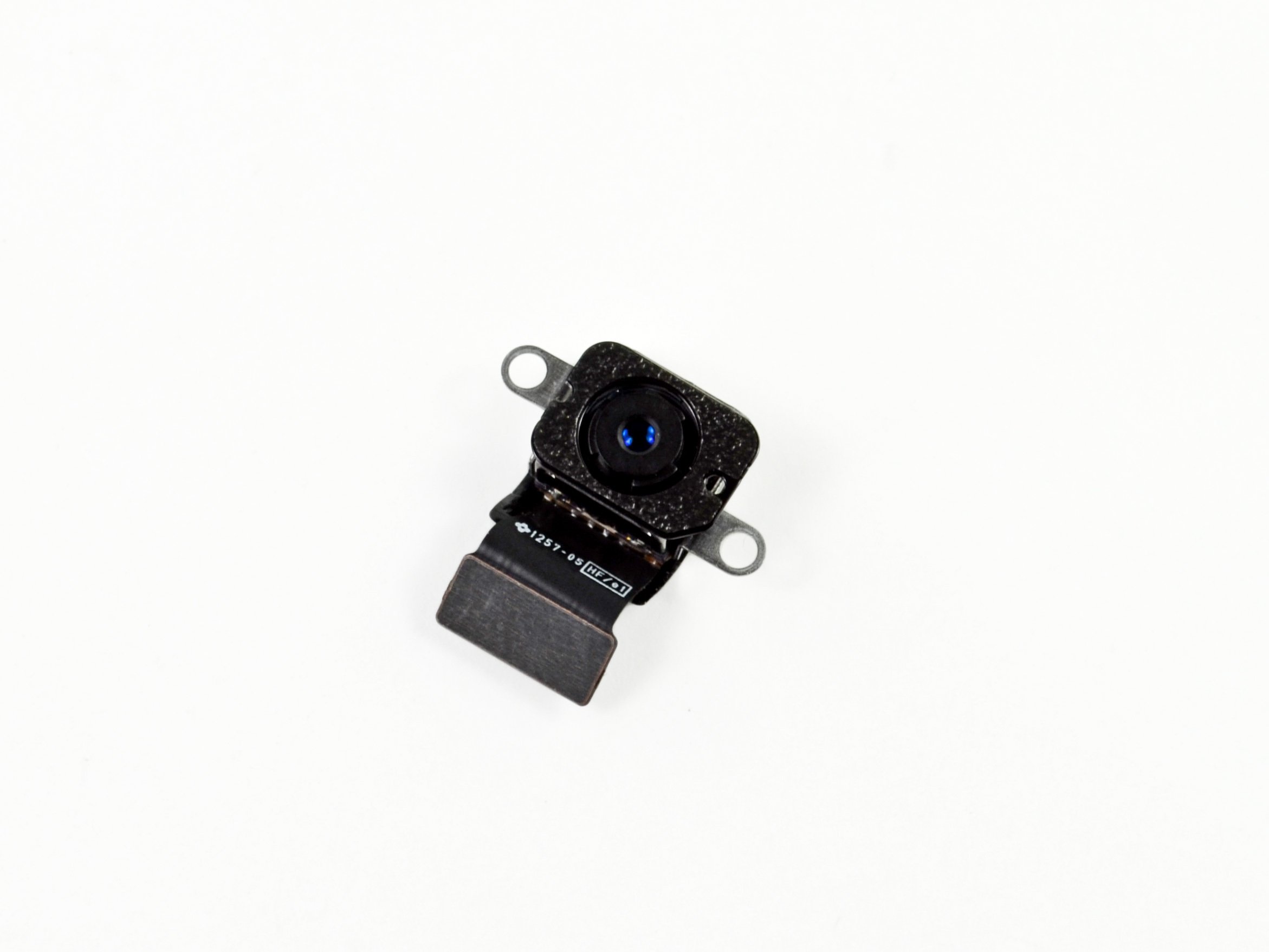
Step 72

Gently lift up right at the connector— steer clear of the socket itself.
– Grab that trusty spudger and gently pry off the rear-facing camera connector from the logic board. It’s a simple move!
– Now, just tuck that rear-facing camera cable to the side like it’s taking a little break.
Tools Used
Step 73


Gently lift only on the connector— steer clear of the socket itself!
Heads up! Newer iPads have a little tape loop hooking this connector to its socket on the logic board. You’ll need to carefully snip that tape to free up the headphone jack. No worries, you got this!
– Grab the flat side of your spudger and gently disconnect the headphone jack connector from the logic board.
– Now, fold the headphone jack cable out of the way so it doesn’t get in your way while you’re at it.
Tools Used
Step 74


Gently pry only at the connector—leave the socket alone. Give it some space!
– Gently pry up the microphone cable connector from the logic board using the flat end of your trusty spudger.
Tools Used
Step 75


– Peel away any tape that’s covering the upper button assembly cable connector. Let’s keep things tidy as we dive into the repair adventure!
Step 76


– Take the spudger’s pointy end and gently pry up the little retaining flap on the upper button assembly cable connector.
Tools Used
Step 77


– Gently slide the upper button assembly cable straight out of its ZIF connector. No need to rush, just a smooth move and you’re good to go!
Step 78
Hold your iPad upright and take a peek down the Lightning port to spot these screws.
– Unscrew those two 3.3 mm Phillips #000 screws holding the Lightning port in place. You’ve got this!
Step 79


Next up, you’ll grab an iOpener to gently warm the back of the iPad, making the adhesive holding the logic board nice and soft.
When you place the iOpener on each spot shown, keep it there for about a minute to let the heat work its magic through the rear case.
– The adhesive consists of six pieces of black foam tape—keep this step handy as you heat and pry, so you know exactly where each piece is chilling.
Tools Used
Step 80

A little extra time is totally fine! Just keep in mind that if your iOpener hangs out on the rear case for too long, you might need to give it another warm-up and a fresh application.
– Grab your trusty heated iOpener and place it over the rear-facing camera end of your iPad. Let it chill there for at least a minute to work its magic on the adhesive lurking beneath the rear case.
Tools Used
Step 81


As you move through the next few steps, when you’re gently prying away the adhesive holding the logic board in place, start by testing lightly to check if the adhesive has softened up. If it’s still tough, simply reheat the iOpener and place it back on the rear case for a bit longer.
– Gently slide an opening pick under the logic board, right between the front-facing camera and the battery. Take it slow here, no rush!
– Now, carefully glide the pick toward the front-facing camera connector, and stop once you hit the bend in the logic board. It should feel smooth, like you’re on the right track.
Tools Used
Step 82


– Gently slide an opening pick underneath the logic board, starting from the front-facing camera and moving towards the rear-facing camera. Keep it steady and take your time – you’ve got this!
Step 83

Once again, give that iOpener a little time to work its magic! Let it chill on the rear case for at least a minute to help loosen up that adhesive.
– Grab your heated iOpener and gently slide it along the bottom edge of your iPad. Give it a few moments to work its magic, softening the adhesive.
Tools Used
Step 84


The Lightning connector cable has decided to stick around a bit too long thanks to some adhesive. To free it, gently slide an opening pick between the cable and the case. Just be super careful not to slice into the Lightning connector cable itself – we want to keep it intact!
– Slide an opening pick beneath the Lightning cable where it connects to the logic board.
– Gently glide the pick down and around the curve of the cable.
Step 85


Take it slow and steady. If the opening pick isn’t sliding in smoothly, give it another round of heat and try again. Don’t rush it—too much force and you might accidentally cut that Lightning connector cable. Patience is key!
– Gently slide the opening pick beneath the cable, making sure to pause right before it curves towards the Lightning connector. Keep it smooth and steady!
Step 86


– Now, gently slide the opening pick in between the battery and the Lightning connector to break free the last bits of adhesive holding that cable down. You got this!
Step 87


– Gently pull the Lightning connector straight out from its snug little home in the rear case.
Step 88

Give the iOpener a minute to work its magic and loosen up that pesky adhesive from the back case.
– Gently place a warm iOpener on the left side of the back case, right where the logic board is sticking to it.
Tools Used
Step 89


– Start by carefully inserting a plastic opening tool into the rectangular gap near the top of the logic board. Gently pry the logic board away from the rear case.
– Once the opening tool is under the logic board, smoothly slide it down the length of the gap to release the top end of the logic board from the adhesive.
Step 90


Gently lift the end of the logic board. If you feel a lot of resistance, it’s a sign to pause and give the iOpener another go. You’ve got this!
– Gently lift the logic board from the lower edge of the rectangular gap, just next to the EMI shield. A little patience goes a long way here!
Tools Used
Step 91


Be careful not to slice into the battery with the opening pick; a punctured battery can lead to some serious trouble. If you feel any resistance, just reheat that iOpener and give it another go.
– Gently slide an opening pick between the logic board and the battery. It’s like sneaking a note between two friends without them noticing.
– Carefully work the pick from the base to the center of the logic board to cut through the adhesive. Think of it like cutting through a sticky situation with finesse.
Tools Used
Step 92


– Gently slide the pick along the length of the logic board. Think of it as giving your device a little spa treatment!
– Once the adhesive is sliced, carefully lift the battery side of the logic board away from the rear case. You’re almost there!
Step 93


– Gently lift the logic board starting from the side closest to the battery until you can slide an opening pick under the opposite edge.
– Carefully cut through any adhesive securing the outer edge of the logic board to the back case.
Step 94

– Carefully lift out the logic board from the iPad to get things rolling.
Step 95


Just a friendly reminder to avoid overheating your iOpener during the repair! Give it a two-minute break before you reheat it, and remember, no more than 30 seconds in the microwave. Let’s keep things cool and smooth!
Get ready to bring the heat! These steps will guide you in using warmth to loosen up the glue that’s holding the battery in place. If you want a safer route, consider using a solvent like adhesive remover to gently break down that sticky bond between the battery and the rear case.
Keep an eye on your iOpener—it might cool off after a bit of use. If it does, just pop it back in the microwave for another 30 seconds before moving on to the next spot.
– Pop the iOpener in the microwave for 30 seconds to warm it up.
– Set the warmed iOpener right in the middle of the iPad’s back and let it chill there for 90 seconds to loosen the battery glue.
– Slide the iOpener over to the right side, away from the rear camera, and give it another 90 seconds to work its magic.
– Finally, move the iOpener to the right edge of the iPad and let it hang out there for 90 seconds.
Tools Used
Step 96


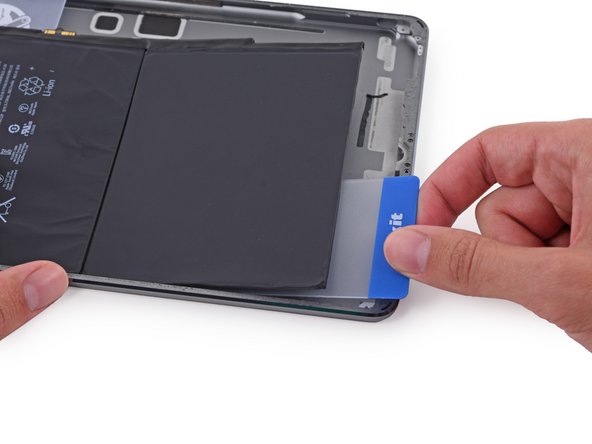
As you work through this step, you’ll be sliding thin plastic cards between the battery and the iPad’s rear case to gently separate the adhesive holding the battery in place. Keep those cards nice and flat to avoid bending the battery—nobody wants a cranky battery leaking bad stuff!
If you hit some stubborn resistance, just warm up the iOpener again and give that adhesive a little extra time to chill out and get soft.
– Slide a plastic card under the bottom right corner of the lower battery cell to gently pry it up.
Tools Used

Step 97


– With the card inserted about halfway, gently nudge it up towards the top of the iPad, but stop just short of the battery contact post.
Step 98


– Gently lift the card up just enough to clear the battery contact mounting post on the rear case.
– Carefully slide the card from the middle of the battery cells toward the upper right corner.
Step 99


– Slide a second plastic card about halfway under the left battery cell to keep it from sticking back when you reheat with the iOpener.
Tools Used
Step 100

– Get your trusty iOpener and pop it on the right side of the battery, away from the cards. This will help loosen up that pesky adhesive like a charm!
Tools Used
Step 101


– Carefully slide the card around the bottom right corner of the battery to loosen it up.
Step 102


– Gently slide the plastic card down to the lower left corner of the battery — like you’re sneaking it into place!
Step 103


– Push the card in a bit more to break up as much of the battery adhesive as you can manage.
– Slide the plastic card under the bottom left corner of the battery.
Step 104


Carefully slide the card beneath the front-facing camera and headphone jack cables — we don’t want any accidental snips!
– Gently glide the card around the upper right corner of the battery, like you’re giving it a little dance move!
Step 105


Take a moment to carefully glide the card over the front-facing camera and headphone jack cables—let’s keep those little guys safe and sound!
– Gently slide the plastic card to the upper left corner of the battery. This little move will help you loosen things up. Take it slow, but steady—you’re doing great!
Step 106


– Push the card in a bit more to crack through as much of the battery adhesive as possible.
– Slide the plastic card under the top left corner of the battery.
Step 107


– Time to put everything back together! Just retrace your steps and reverse the order of what you did. If you find yourself in a pickle, don’t hesitate to schedule a repair for some extra hands.
Success!