Duration: 45 minutes
Steps: 13 Steps
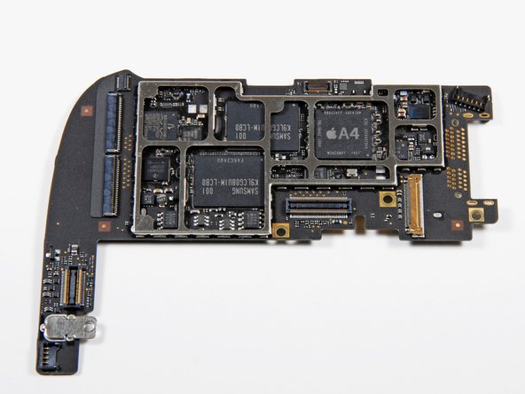
Let’s dive into this guide and carefully take out the iPad’s logic board step by step.
Step 1


Pop on some safety glasses to keep those peepers safe, and handle the LCD screen gently to avoid any oops moments.
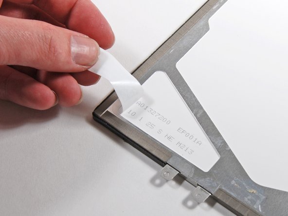
Slap on some tape to keep those pesky glass bits in check and make the screen sturdier as you pop it off.
– If your display glass has seen better days and is cracked, let’s keep it from getting worse and avoid any oops moments during your repair by slapping some tape on it.
– Grab some clear packing tape and lay down overlapping strips over the iPad’s display until it’s completely covered. Think of it as giving your device a protective hug!
– Now, follow the rest of the guide as best as you can. Just a heads up, once that glass starts to crack, it might decide to keep cracking while you work. You might need to break out a metal prying tool to scoop out the glass bits. But no worries, you’ve got this!
Step 2


Alright, it’s time to gently pry the iPad’s display assembly away from its aluminum body. Take it slow and follow the steps closely—those display clips are delicate and don’t appreciate rough handling!
Oops! Snapped a clip? No worries—replacement clips are available, so your device can be as good as new.
– There are 14 metal clips holding the display assembly firmly in place, as seen on the left. When prying in the next steps, take your time to carefully work around these clips—try not to slice through them with your opening tool!
Step 3


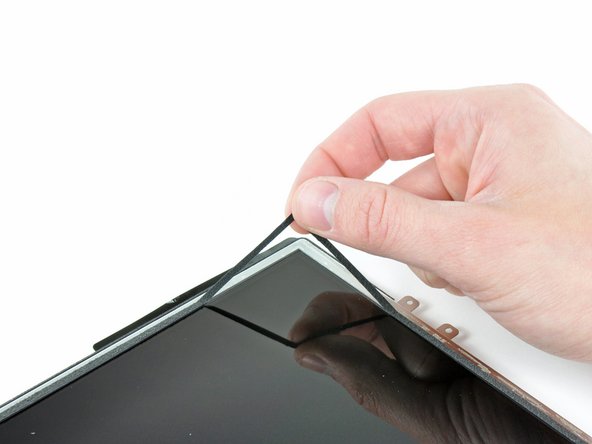
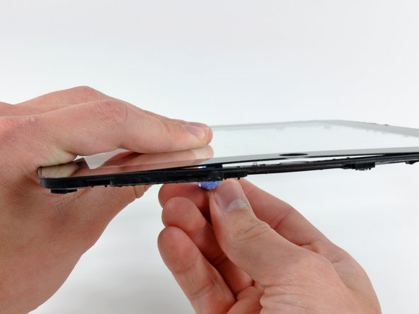
– Slide a metal spudger into the gap between the top edge of the display assembly and the rear panel assembly.
– Give the spudger a little twist away from you to pop those tabs loose along the top edge of the display.
– Now, grab a second metal spudger and slide it back into that same spot to keep those tabs from snapping back in place.
Tools Used

Step 4


Gently wiggle your pry tool—if it feels stuck, switch spots and try again with care.
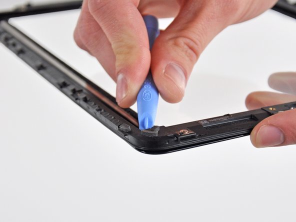
– Grab a spudger and gently work your way down the right edge of the iPad. Patience is key!
– The front panel is held in place by some metal clips at the top, bottom, and left, while the right side has some plastic tabs that slide into the backplate. It’s like a jigsaw puzzle!
– Once those clips are free, carefully lift the left side of the front panel and slide it to the left to release the tabs from the aluminum backplate. You’re almost there!
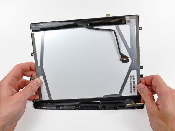
Step 5

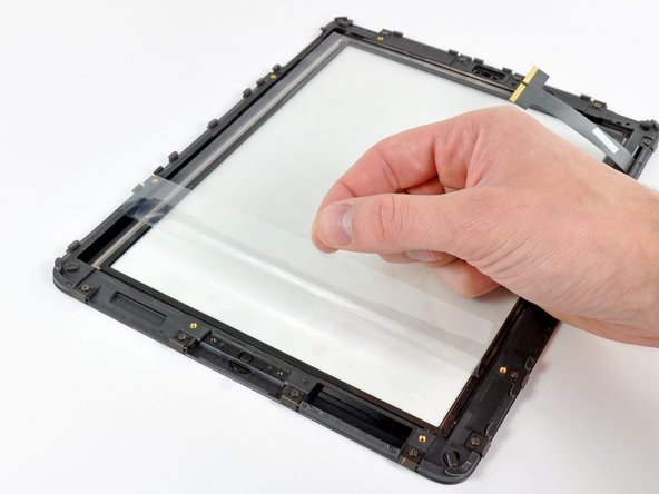
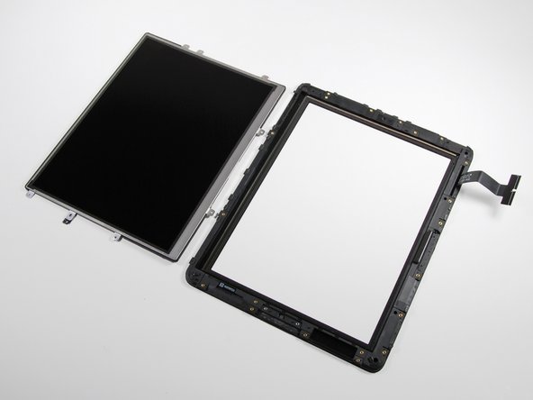
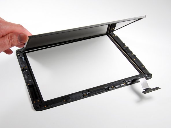
Hold off on removing the display for now—it’s still connected to the rear panel assembly. Patience is key!
– Gently lift the display assembly from the rear panel by the bottom edge. Take it slow and steady—you’ve got this!
Step 6

– Alright, time to free up the display assembly! In these next steps, we’re going to unplug the three cables that connect the display to the logic board. Each one controls a specific part, so here’s the breakdown:
– Digitizer
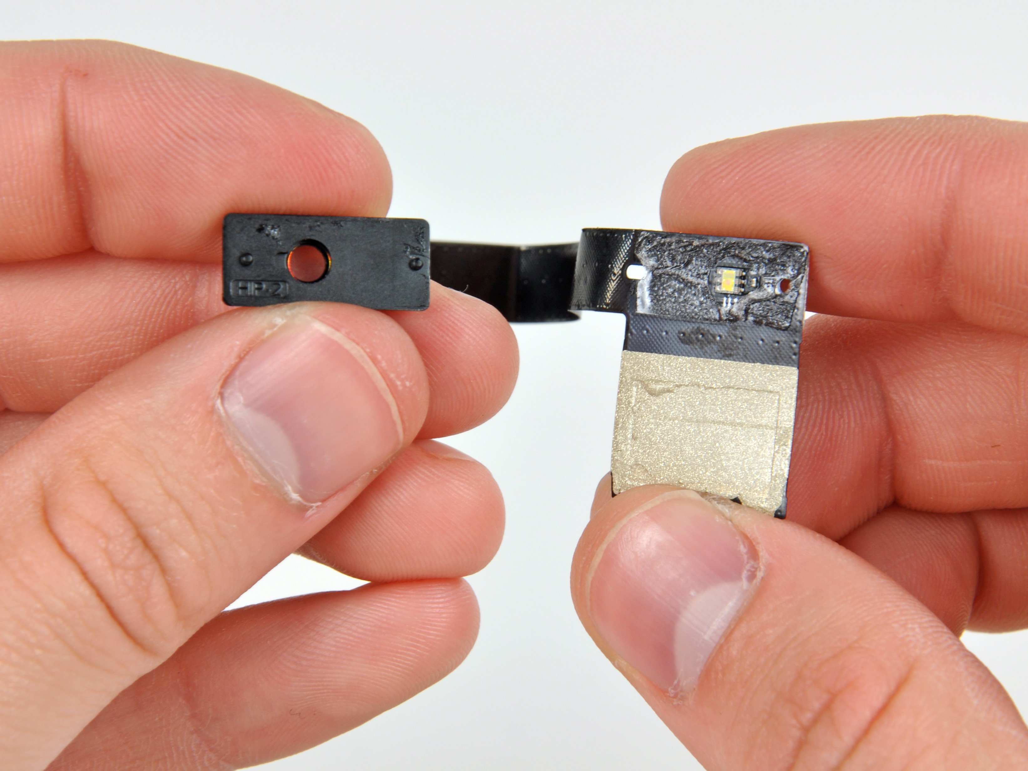
– Ambient Light Sensor
– Display Data Cable
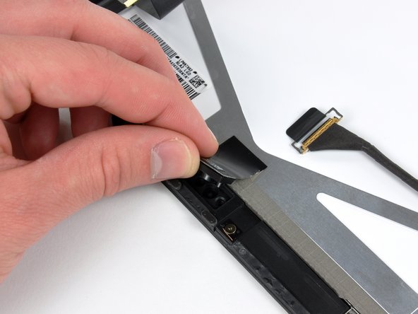
Step 7


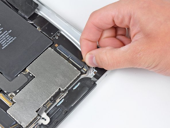
Make sure you’re lifting the retaining flap and not the socket itself. You’ve got this!
– Grab a plastic opening tool and use the edge to gently flip up those little retaining flaps that are holding the digitizer ribbon cables in place on the logic board.
– Now, carefully pull the digitizer ribbon cables straight out of their sockets. Take your time, they should come out with ease.
Step 8

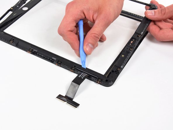
– Grab your trusty plastic opening tool and gently pop the ambient light sensor connector out of its socket by prying upward. Easy does it!
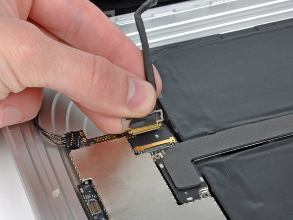
Step 9


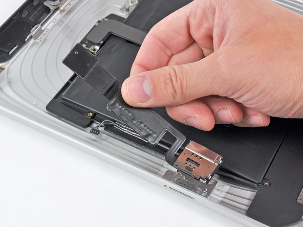
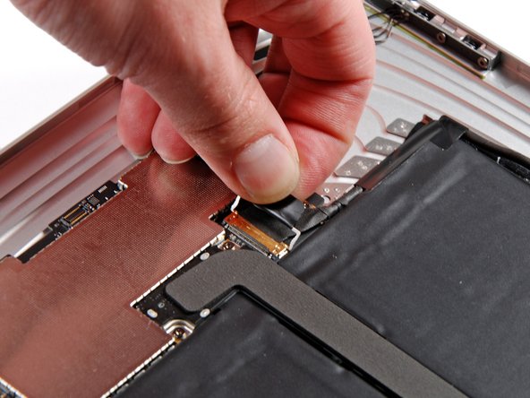
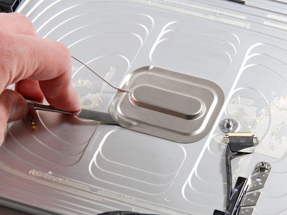
Gently slide the connector away from the logic board, keeping it level with the board’s surface.
– Gently lift the shiny metal retainer using its trusty black plastic pull tab—think of it as opening a treasure chest for your tech!
– Slide the cable connector out of its socket with care, like you’re unplugging a secret agent’s gadget.
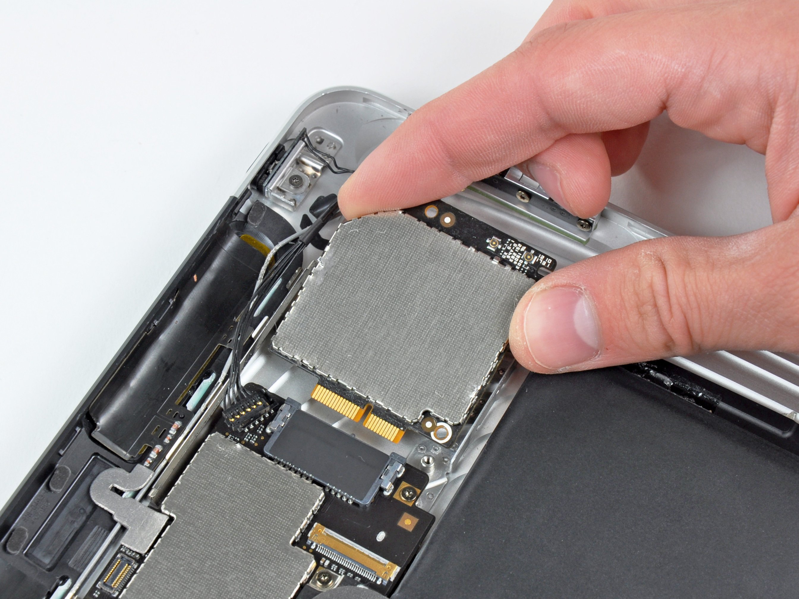
Step 10

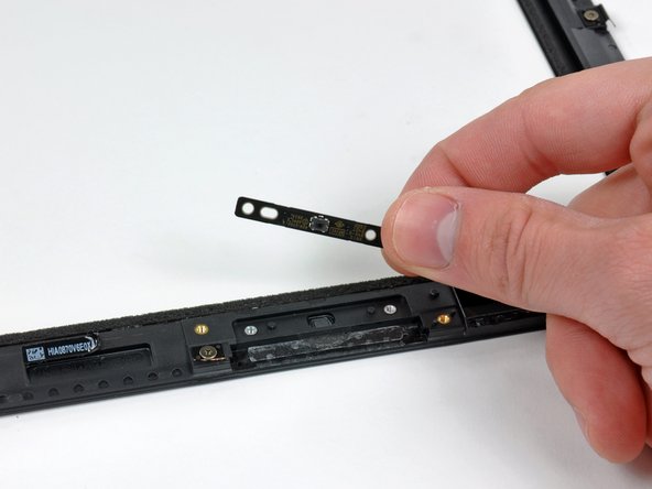
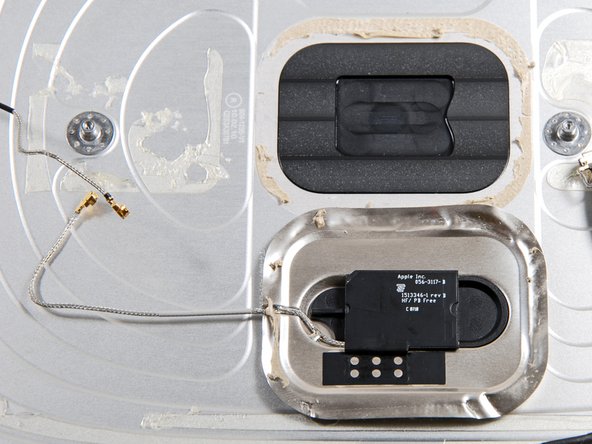
– Gently separate the display assembly from the rear panel assembly.
Step 11


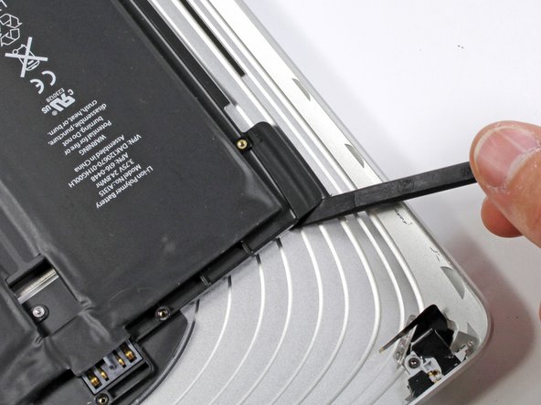
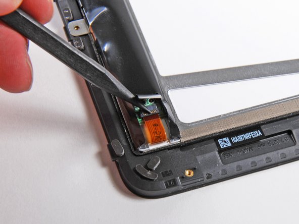
Make sure you’re gently prying up the retaining flap, not the socket itself—handle with care!
– Grab your trusty plastic opening tool and get ready for action:
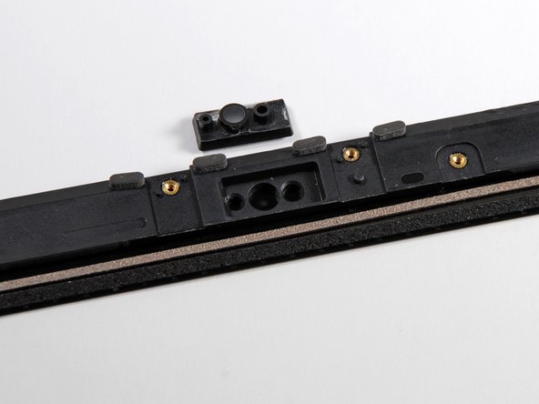
– Gently lift up the little flap on the ZIF ribbon cable socket near the headphone jack—no muscles needed here, just a careful touch!
– Slide the headphone jack ribbon cable out toward the left side of your iPad to disconnect it. Smooth moves!
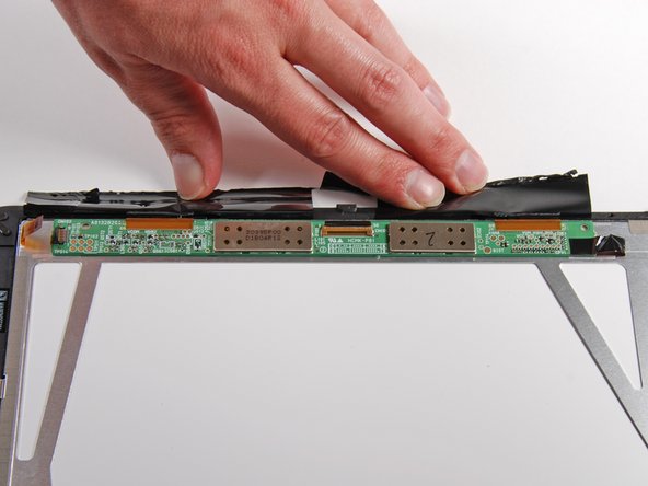
– Pop the side button connector off the logic board by prying from underneath the wires. Take it slow and steady.
– Lift the speaker connector out of its socket on the logic board, going underneath the speaker wires. You’re almost there!
Step 12

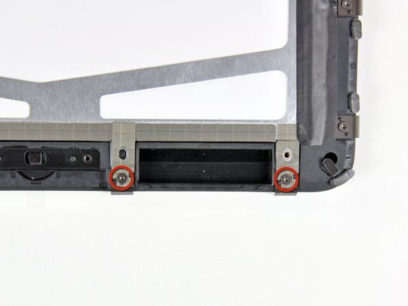
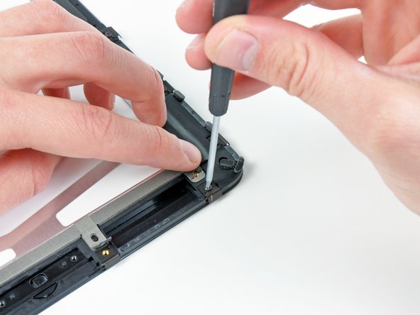
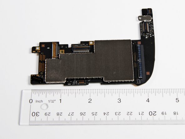
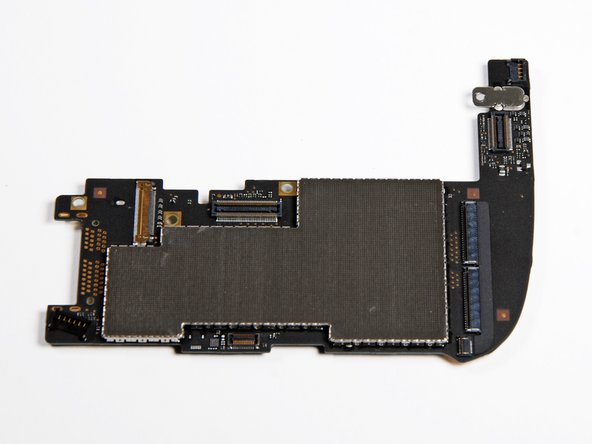
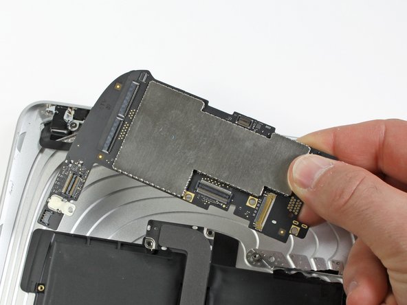
– Let’s get down to business! First off, you’ll want to take out those screws that hold the logic board snug against the rear panel assembly.
– There are two 4.56 mm T5 Torx screws just waiting for you to give them a twist.
– And don’t forget about the two 3.76 mm T5 Torx screws—they’re just as important!
Step 13

– Put everything back together by following these steps in reverse—easy peasy!
Success!