Duration: 45 minutes
Steps: 23 Steps
Get ready to give your iPad a fresh start by swapping out that tired battery! Follow along with this handy guide and let’s breathe some new life into your device. And remember, if you hit a snag, you can always schedule a repair!
Step 1


Pop on some safety glasses to keep your eyes protected, and handle that LCD screen with care—no cracks, okay?
This trick keeps those pesky glass shards from flying everywhere and helps hold things together while you pry and lift the display.
– If your display glass is looking a bit worse for wear, let’s keep it from shattering further and protect your hands while you work by adding some tape. A little prep goes a long way!
– Grab some clear packing tape and lay down overlapping strips across the iPad’s display until you’ve got the whole face covered. It’s like giving your device a protective hug!
– Now, roll up your sleeves and follow the guide as best as you can. Just a heads up, once the glass starts to break, it might keep cracking as you go. You might find a metal prying tool handy for scooping out the glass. If it feels a bit too tricky, don’t hesitate to schedule a repair for some extra help!
Step 2


Get ready to gently separate the iPad’s display assembly from its aluminum body! Take a moment to glance through these steps and follow them closely to keep that display assembly and those delicate clips safe and sound.
If you happen to snap a clip or two, no worries! You can grab some replacements right here.
– There are 14 metal clips holding the display assembly in place, shown at left. When prying in the next steps, try to carefully work around these clips without slicing through them with your opening tool.
Step 3


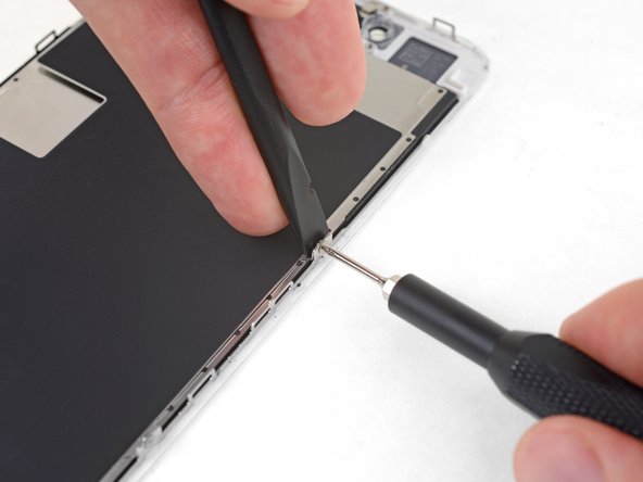
– Slide a metal spudger into the gap between the top edge of the display assembly and the rear panel assembly.
– Gently twist the spudger away from you to free up the tabs along the top edge of the display.
– Pop in a second metal spudger between the top edge of the display assembly and the rear panel assembly to hold those tabs in place—no snapping back allowed!
Tools Used


Step 4


Go slow and easy—if it feels stuck, pick a different spot to pry. Patience pays off!
– Grab your trusty spudger and carefully slide it along the right edge of the iPad.
– The front panel is snapped onto the aluminum back with metal clips along the top, bottom, and left edges. The right side, however, uses plastic tabs that slot neatly into the backplate’s recesses.
– Once you’ve popped those clips free, gently lift the left side of the front panel and slide it leftwards to wiggle the tabs out from the aluminum backplate.
Tools Used
Step 5

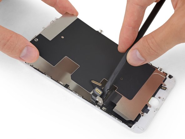
Hold off on removing the display for now, as it’s still connected to the rear panel assembly. Patience pays off!
– Gently lift the display assembly upward by its bottom edge, separating it from the rear panel like you’re flipping the cover of your favorite book.
Step 6

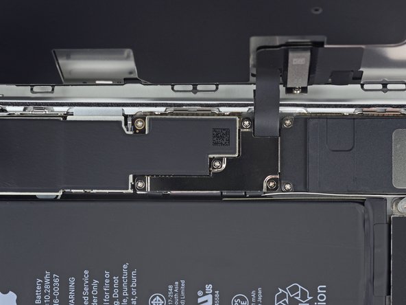
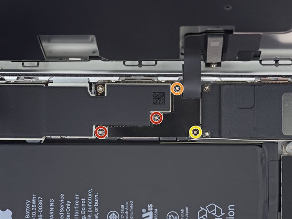
– Alright, let’s get those cables disconnected from the display assembly like a pro! First up, we need to unhook three cables that link the display assembly to the logic board. Here’s what you’re dealing with:
– Digitizer
– Ambient Light Sensor
– Display Data Cable
Step 7


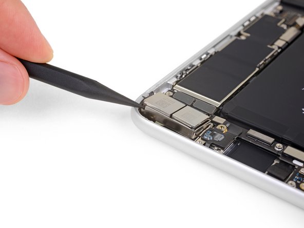
Heads up: flip up the retaining flap gently—don’t try to lift the socket itself!
– Grab your trusty plastic opening tool and gently lift the little retaining flaps that are keeping those digitizer ribbon cables snugly in their spots on the logic board. You’ve got this!
– Now, with a steady hand, pull those digitizer ribbon cables straight out from their sockets. Easy peasy!
Step 8

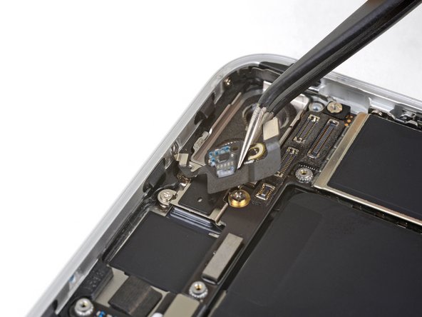
– Grab a plastic opening tool and gently nudge the ambient light sensor connector upwards to pop it out of its socket. You’ve got this!
Step 9


Gently pull the connector away, keeping it parallel to the surface of the logic board.
– Lift the metal retainer by its black plastic pull tab to disconnect the display data cable from the main board. You’ve got this!
– Gently pull the cable connector away from its socket. Easy peasy!
Step 10

– Carefully pop off the display assembly from the rear panel—it’s easier than it sounds!
Step 11


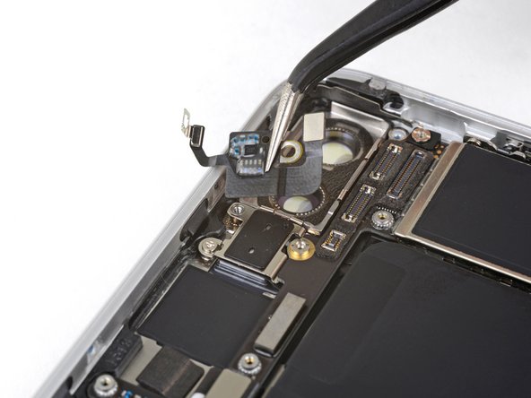
Make sure you’re lifting up on the retaining flap, not the socket itself. You’ve got this!
– Grab your trusty plastic opening tool and gently use the edge to:
– Carefully lift the ZIF ribbon cable retaining flap near the headphone jack, just like flipping up a flap on a treasure chest.
– Now, pull that headphone jack ribbon cable to the left side of the device to detach it from its cozy socket.
– Next, gently pry the side button connector off the logic board, making sure to sneak under those little wires.
– Finally, pry the speaker connector away from its socket on the logic board, again, slipping under the speaker wires. Easy does it!
Step 12

– Let’s get those screws out to free up the logic board from the rear panel.
– Start with the two 4.56 mm T5 Torx screws.
– Then tackle the two 3.76 mm T5 Torx screws.
– Keep those screws safe—you’ll need them again!
Step 13

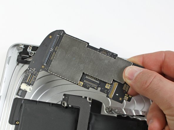
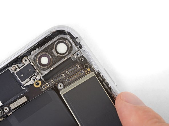
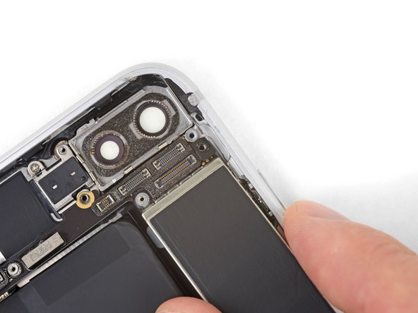
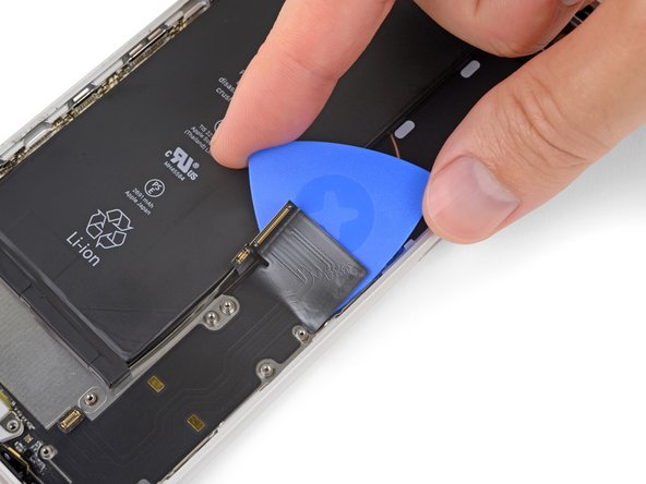
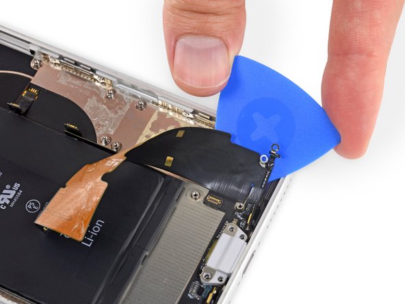
– Gently slide the edge of your trusty plastic opening tool under the dock cable connector and pop it up with care—just like lifting a tightly sealed lid!
– Once that’s done, give the logic board a little lift and set it free from the rear panel assembly. It’s like letting a bird out of its cage!
Step 14

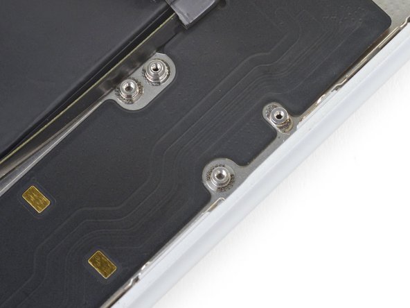
– Unscrew the pair of 2.84 mm T5 Torx screws holding the speaker assembly to the rear panel. Easy does it!
– Next, take out that lone T5 Torx screw right in the middle of the dock cable, fastening it to the rear panel. One screw to rule them all!
Step 15

– Unscrew the two 2.84 mm T5 Torx screws holding the dock connector cable to the back case. Keep these screws safe—they’re the tiny heroes of this step!
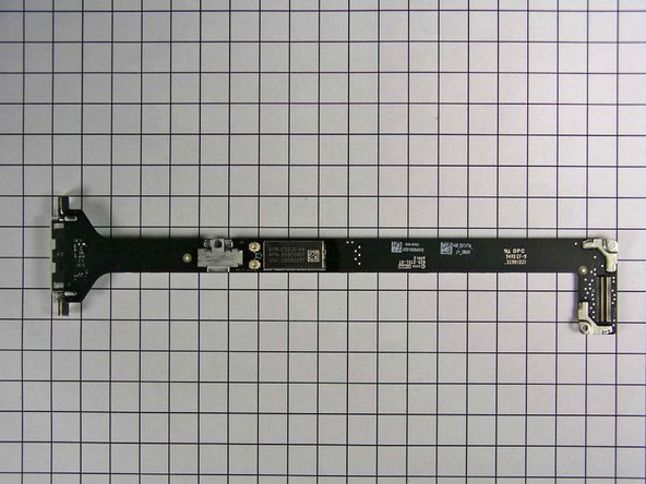
Step 16

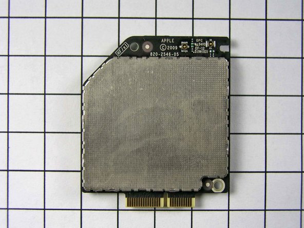
– Grab your trusty plastic opening tool and gently pry off the plastic cover that’s keeping the WiFi/Bluetooth board and dock connector cable cozy. You got this!
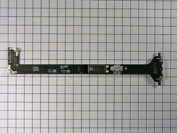
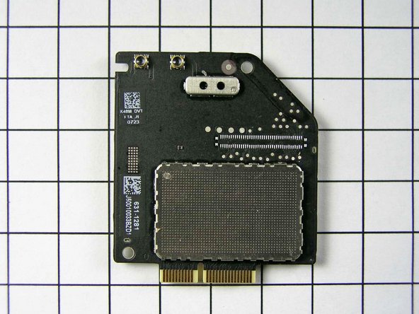
Step 17

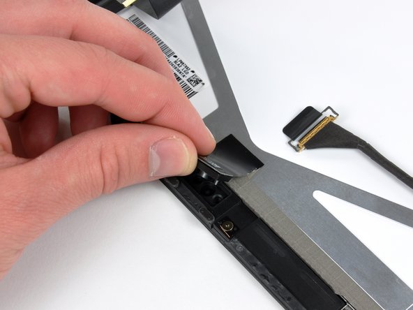
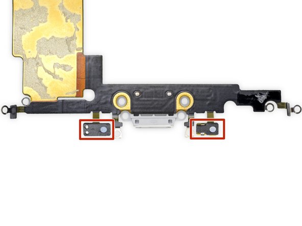
– Gently nudge the Wi-Fi and Bluetooth antennas out of their cozy little homes on the Wi-Fi/Bluetooth board.
Step 18

– Gently pop the dock connector cable out from the back panel assembly.
Step 19


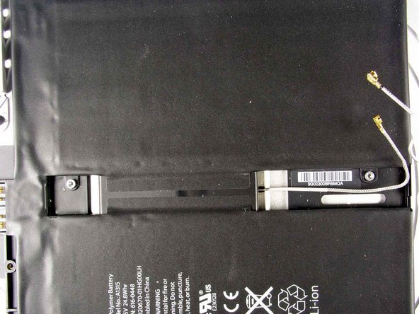
– Gently guide the speaker cable away from the left side of the battery case. You’re doing great!
– Carefully thread the Wi-Fi antenna through its designated channel in the speaker assembly. Nice work!
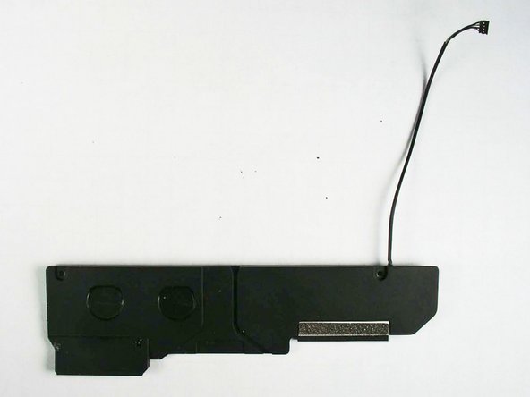
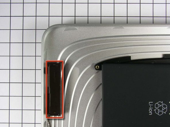
Step 20


– Gently lift the speaker assembly and slide it forward just enough to free the ports from the bottom edge of the lower case.
– Carefully take the speaker assembly away from the rear panel assembly.
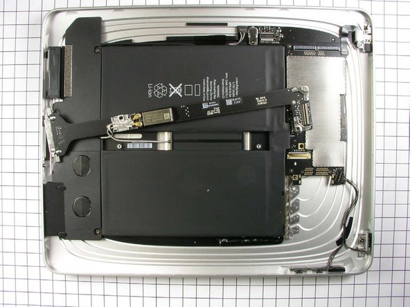
Step 21


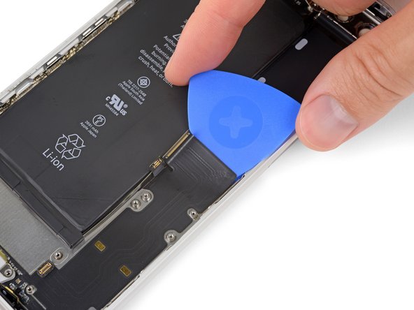
The battery is glued down with way more adhesive than you’d expect. Take it slow and steady, you got this!
Keep prying gently until the battery’s right side pops free from the rear panel—almost there!
– Grab your trusty spudger and gently wiggle that battery up from the lower case like you’re giving it a little nudge to say, ‘Hey, you can do it!’
– Keep that groove going by wiggling the spudger along the right side of the battery, making the gap a bit bigger. You’re almost there!
Tools Used
Step 22


Keep going until the top of that battery is free from the rear panel! You’ve got this!
– Gently wedge the flat side of a spudger beneath the top edge of the battery and keep on working that adhesive loose.
Tools Used
Step 23


– Now it’s time to put everything back together! Just retrace your steps in reverse, and you’ll be good to go. If at any point you feel overwhelmed, don’t hesitate to schedule a repair. You’ve got this!
Success!