Duration: 45 minutes
Steps: 32 Steps
Most replacement home buttons might not play nice.
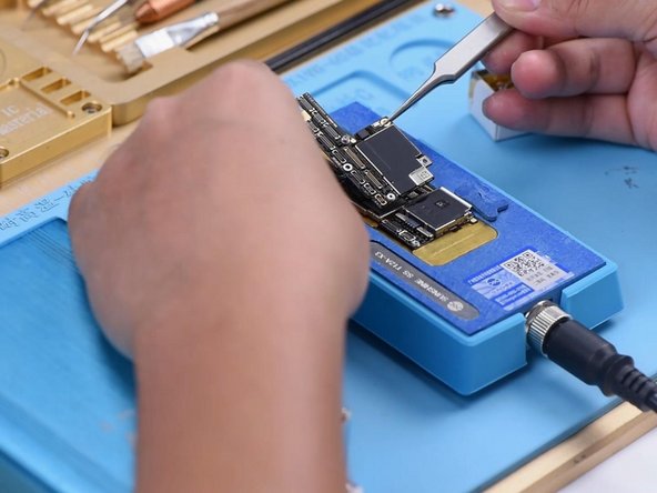
The home “button” on your iPhone 8 Plus is actually a solid-state sensor that comes packed with Touch ID (fingerprint recognition) magic! Now, here’s the kicker: most replacement home buttons are a no-go, so make sure to double-check before you dive into your repair adventure. Your original home button is like a unique snowflake, paired with the logic board right at the Apple factory, and without their special calibration, even a genuine home button from another iPhone won’t do the trick. If your home button is feeling a little broken, your best bet is to get a specially-made universal-style button. Just a heads up though, these replacements will only act as a button—Touch ID won’t be making an appearance. If you’re just swapping out a cracked screen, you can follow this guide to carefully remove and transfer your original home button to the new screen, keeping all functions intact, including Touch ID! Remember, to avoid any accidental drama with the display cables, it’s a smart move to completely detach the display assembly before getting into the home/Touch ID sensor repairs. But hey, if you’re feeling confident, feel free to skip right to the home/Touch ID sensor section and get going!
Step 1

Before you dive in, make sure your iPhone battery is below 25%. Trust us, a fully charged lithium-ion battery and sharp tools don’t mix—unless you’re into sparks and surprises.
Cracking open your iPhone’s display does break its waterproof seals, so if you’re rolling without fresh seals, keep it dry when you put everything back together.
– Make sure to power off your iPhone before you start taking it apart.
– Unscrew the two 3.5 mm pentalobe screws located at the bottom edge of your iPhone.
Step 2


Don’t let your pick go on a wild adventure inside your device! Mark how deep it should go to keep everything safe and sound.
If you’re feeling fancy, mark different measurements on each corner of the pick for maximum precision.
Feeling creative? Stick a coin to your pick about 3 mm from the tip—it’s a quirky way to keep things on track.
– Grab your opening pick and make a little mark 3 mm from the tip using a permanent marker. This helps keep your angles on point!
Step 3


Put on those safety glasses to keep your eyes safe from any sneaky shards that might decide to take a little vacation during the repair.
If your iPhone screen is cracked, tape over the glass to keep the shards from flying and to keep your fingers safe while you work.
If the suction cup isn’t sticking, a little dab of superglue can help it hold on tight to the screen.
– Cover the iPhone’s screen with overlapping strips of clear packing tape until the entire front is sealed up like a pro.
– If the suction cup refuses to stick in the next steps, no worries — just fold a sturdy piece of tape (think duct tape) into a little handle and use that to lift the screen instead.
Step 4


The next three steps show off the Anti-Clamp, a nifty tool that makes popping your device open a breeze. If you’re skipping the Anti-Clamp, just jump ahead three steps for a different way to crack things open.
Curious how to wield the Anti-Clamp like a pro? Check out the full guide for all the tips.
If your iPhone is smoother than a jazz sax solo and the Anti-Clamp keeps slipping, slap some tape on there to give it extra grip.
– Pull the blue handle back to release the Anti-Clamp’s arms—it’s like giving them a little stretch!
– Slide those arms over either the left or right edge of your iPhone. Make sure they’re snug!
– Place the suction cups near the bottom edge of your iPhone, just above the home button—one on the front and the other on the back. They’ll be your trusty sidekicks!
– Give the cups a good squeeze to create a strong suction. You’re on your way to a successful repair!
Step 5


– Give that blue handle a gentle tug forward to secure those arms in place.
– Now, twist that handle clockwise a full 360 degrees, or keep going until you see those suction cups start to stretch a bit.
– Keep an eye on those suction cups to make sure they’re staying in sync. If they start to drift out of alignment, just loosen them a tad and realign those arms like a pro!
Step 6


Turn no more than a quarter at a time, then take a breather for about a minute. Let the Anti-Clamp and some patience do the heavy lifting!
You can also try a hair dryer, heat gun, or hot plate—but remember, too much heat might hurt the screen or battery, so take it easy.
If the Anti-Clamp doesn’t open up enough space, warm it up a bit more and twist the handle another quarter turn.
– Warm up that iOpener and slide it through the arms of the Anti-Clamp like a pro.
– Bend the iOpener so it rests snugly on the bottom edge of your iPhone.
– Give it a minute to let that adhesive loosen up and create a lovely little gap for you.
– Once the Anti-Clamp has opened things up nicely, slip an opening pick under the screen.
– Feel free to skip the next three steps. You’ve got this!
Tools Used

Step 7

The next three steps will walk you through how to gently separate the screen using a suction cup.
Warming up the bottom edge of your iPhone will help loosen the adhesive holding the display, making it much easier to lift.
– Grab your hairdryer or prep your iOpener, then warm up the bottom edge of your iPhone for about 90 seconds. This helps loosen the sticky stuff holding things together, making your next steps way easier!
Tools Used
Step 8


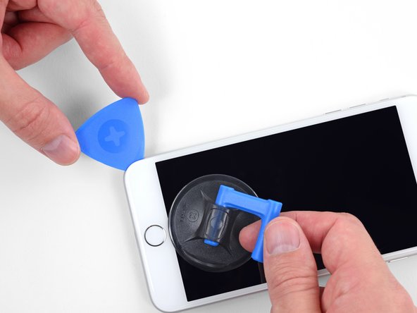
Make sure the suction cup stays clear of the home button – you want it to form a perfect seal with the front glass, not get distracted by that button!
– Place a suction cup just above the home button on the lower half of the front panel to get a good grip.
Step 9


The glue keeping the display stuck on is super tough; breaking that first little gap takes some serious muscle. If it’s being stubborn, crank up the heat a bit and gently wiggle the screen up and down to soften the adhesive until you can sneak your tool in. Keep it cool—you got this!
– Gently tug on the suction cup with steady, consistent pressure until you see a little gap form between the front panel and rear case.
– Slip an opening pick or any slim tool a few millimeters into the gap you just created.
Step 10


– Gently slide your pick along the edge, making your way up to the left side of the phone. Keep heading toward the volume buttons and the silent switch while carefully loosening the adhesive that’s keeping the display stuck down.
– Pause once you reach the top left corner of the display.
Step 11

Heads up! There’s a super-sensitive cable running along the right edge of your iPhone. Skip poking your pick in this spot—you definitely don’t want to give that cable a hard time.
Step 12


Keep your pick insertion under 3 mm to avoid messing up those delicate display cables.
– Gently slide your tool into the lower right corner of your iPhone, and carefully glide it around the corner, moving up the right side. This will help separate the adhesive, and you’ll be on your way to getting things fixed up!
Step 13

Keep the display tilt under 15º to avoid stressing or ripping those delicate ribbon cables.
– Carefully lift the bottom edge of the display by pulling up on the suction cup—easy does it!
Step 14

– Give that little nub on the suction cup a gentle tug to pop it off from the front panel. You’ve got this!
Step 15


– Take your opening pick and glide it along the top edge under the display—let’s gently persuade that last bit of adhesive to let go.
Step 16


– Gently slide the display assembly down a bit (away from the phone’s top edge) to pop those clips loose from the rear case.
Step 17


Hold off on fully lifting the display just yet—there are still some delicate ribbon cables hooking it up to the iPhone’s logic board that need a little TLC.
– Gently open the iPhone by lifting the display from the left side, just like flipping open the cover of a book.
– Prop the display up by leaning it against something sturdy so it stays put while you work your magic on the phone.
Step 18
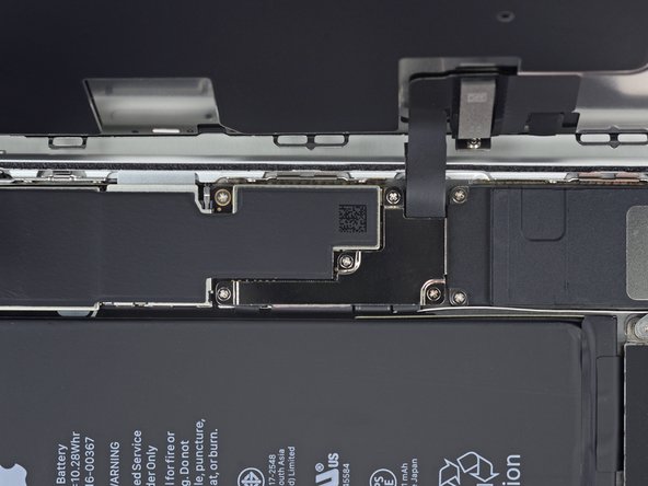
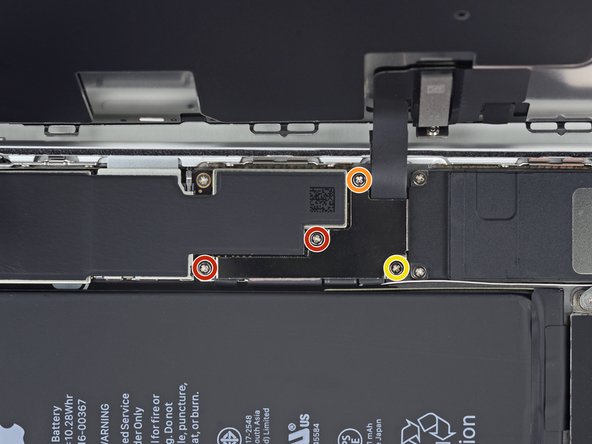
– Remove the four Phillips (JIS) screws holding the lower display cable bracket onto the logic board. Here’s what you’re dealing with:
– Keep your screws organized—mixing these up during reassembly could lead to a world of trouble. Trust me, your device will thank you.
– Two screws, 1.3 mm each
– One screw, 1.4 mm
– One screw, 2.7 mm
Step 19

– Carefully remove the lower display cable bracket. Gently lift it away to avoid damaging anything nearby. Take your time, and remember, patience is key!
Step 20


– Gently use the pointed end of a spudger to lift the battery connector out of its socket on the logic board.
– Carefully bend the connector cable upward just a bit to keep it from accidentally touching the socket and powering up the phone while you work.
Tools Used

Step 21


– Grab a spudger or your trusty fingernail, and gently pry the large lower display connector up from its socket. Be smooth and careful, and it’ll pop right off.
– When you’re ready to reconnect, simply press down on one side of the connector until you hear a satisfying click. Do the same on the other side, but keep the middle clear—pressing there could cause some damage if the connector isn’t lined up perfectly. Take your time, and it should click right into place.
Tools Used
Step 22


– Go ahead and unplug the second lower display cable connector—it’s right behind the one you just disconnected. Keep it steady!
Step 23


– Loosen and remove the two tri-point Y000 screws holding down the bracket that covers the front panel sensor assembly connector:
– One 1.0 mm screw
– One 1.2 mm screw
Step 24

– Take off the bracket that’s keeping the front panel sensor assembly connector under wraps.
Step 25


– Gently pry open the front panel sensor assembly connector using the tip of a spudger or your trusty fingernail to disconnect it from its socket. You’ve got this!
Tools Used
Step 26

– Take off the display assembly with care.
– When putting it back together, feel free to take a moment here if you want to swap out the adhesive around the display edges.
Step 27


– Unscrew those four Y000 screws holding the bracket above the home/Touch ID sensor tight and secure. You’ve got this!
– When putting it all back together, just a gentle touch on those screws will do the trick—overdoing it might leave your home button feeling a bit cranky.
– One 1.2 mm screw
– Three 1.3 mm screws
Step 28

– Carefully take off the bracket holding down the home/Touch ID sensor—it’s the little piece keeping everything in place!
Step 29


If the whole connector starts to pop up instead of just separating, press down on the cable at the top with your spudger, while carefully prying up the left edge of the connector. Take it slow—damaging the cable or connector will knock the sensor out for good.
– Gently pry up from the left edge of the home button cable connector to pop it out of its socket.
Tools Used
Step 30

Avoid overheating the display—it should feel just a little too warm to touch comfortably, not scorching!
Warming up the area around the home/Touch ID sensor is a smart move! It helps to loosen the sticky adhesive that holds its fragile cable in place, making it a breeze to remove safely.
– Gently flip the display assembly over. Grab a hairdryer or your trusty iOpener, and warm up the lower edge of the display for about 90 seconds. This will help loosen up the adhesive holding it in place, making the next step a whole lot easier.
Tools Used
Step 31


– Grab an opening pick and gently ease it under the home/Touch ID sensor cable—you’re just coaxing the adhesive away from the back of the display. Go slow, no need to rush the magic.
Step 32

– If your new screen didn’t come with a front camera and sensor cable, no worries! Just follow these steps to transfer them over.
– Give your shiny new replacement part a good comparison with the original—you might need to swap over some components or peel off any adhesive backings from the new part before you dive into the installation.
– To put everything back together, simply do the steps above in reverse order. Easy peasy!
– When you’re done, don’t forget to take your e-waste to an R2 or e-Stewards certified recycler. Let’s keep our planet happy!
– Things didn’t go as smoothly as you’d hoped? No problem! Try some basic troubleshooting, or if you’re still stuck, feel free to schedule a repair for a helping hand.
Success!