Duration: 45 minutes
Steps: 12 Steps
Step into the world of iPhone X teardown with this straightforward guide. We’ll walk you through each move to get your device apart like a pro, no stress and no fuss.
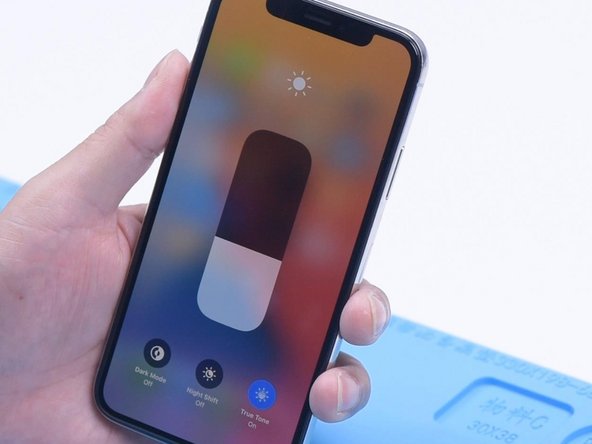
Step 1


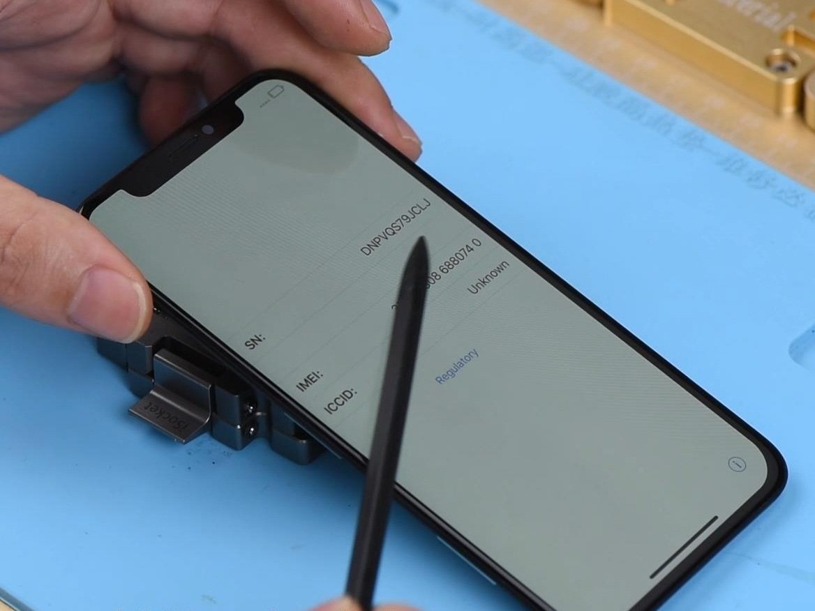
– Hold down the wake button and the volume down button together to power off your phone. Easy does it!
Step 2


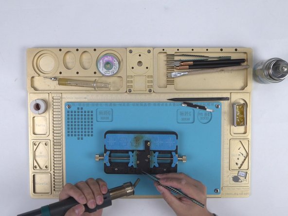
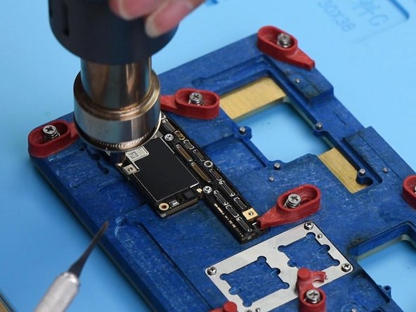
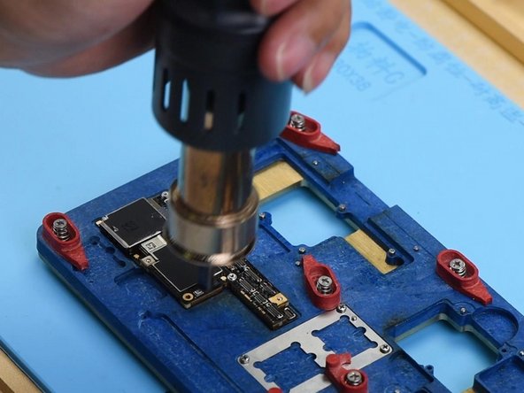
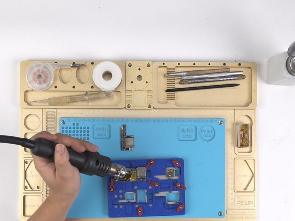
– Grab your Pentalobe screwdriver to loosen those charging port screws. If you’re having a hard time opening the phone, a little heat from a heat gun will make it way easier. Just warm things up a bit and you’ll be good to go!
Tools Used

Step 3


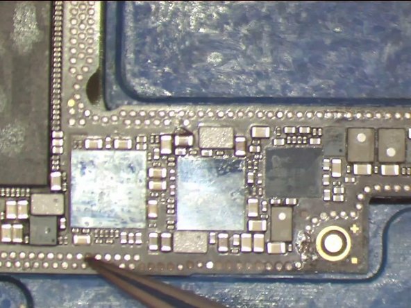
– Loosen and remove the 5 screws shown in the picture below using a tripoint #Y000 screwdriver.
– Keep in mind, these screws are all different sizes, so make sure to remember where each one belongs.
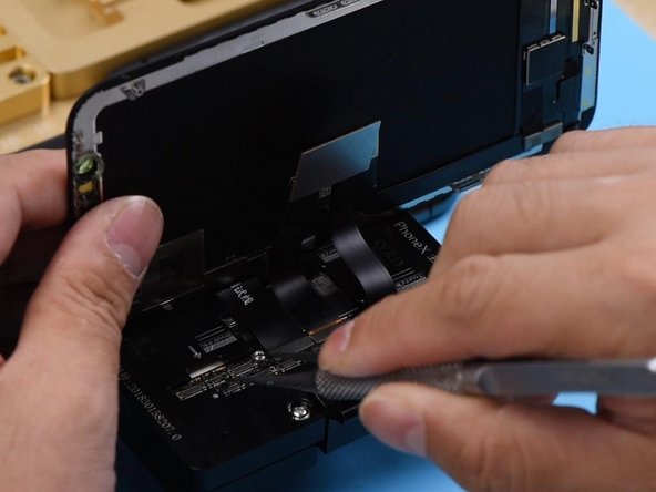
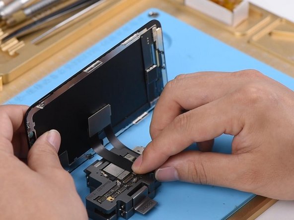
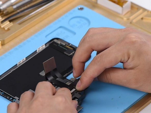
– Carefully disconnect the battery, LCD screen, digitizer, and ear speaker connectors using a spudger.
Tools Used

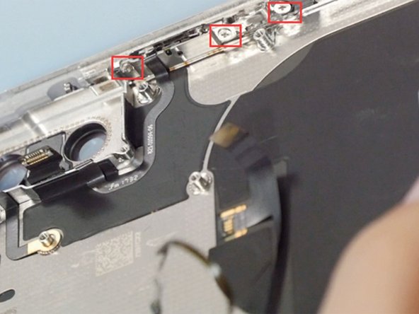
Step 4


– Loosen 3 Y000 screws and gently warm up the flex cable with a heat gun to easily pop out the ear speaker.
Tools Used
Step 5

– Unscrew the two Phillips #PH00 screws holding the metal plate in place, then lift the plate off and gently disconnect the rear camera connectors.
– Heads up: these screws aren’t twins—each one’s got its own vibe, so keep track of where each goes!
Step 6

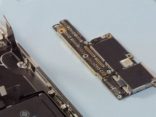
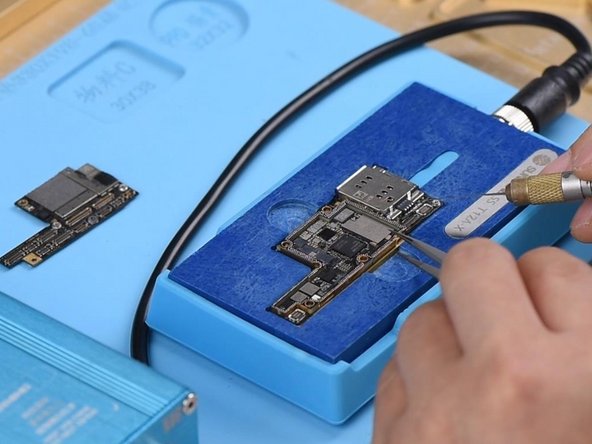
– Gently pop off all the connectors on the motherboard using your trusty spudger—like unplugging little lego blocks.
– Remove the three Phillips #PH00 screws holding down the motherboard. Now you can carefully lift it out. Take your time, and don’t rush—motherboards like a smooth exit!
Tools Used
Step 7


– First things first, let’s get those 8 pesky screws on the retaining plate undone! Once they’re out, gently lift the plate off, but be super careful not to damage that tiny connector snugging up right under the taptic engine.
– Next up, it’s time to say goodbye to the loud speaker and the taptic engine. You’ve got this!
Step 8


– Grab your tweezers and carefully pull out the four battery adhesives. Once they’re free, the battery will be ready to come out. Easy, right?
Tools Used

Step 9


– Give that front-facing camera a little warm-up with a heat gun—it’ll loosen right up and pop off with no trouble.
Tools Used
Step 10


– Unscrew the 4 screws hanging out on the frame as shown. They’re just waiting to be set free.
– Warm up the charging port flex cable a bit—think spa day for your device—then gently lift it out like a pro.
Step 11


– Loosen and take out those 7 screws holding the Wi-Fi flex cable in place. You’ve got this!
– Give that flex cable a little warmth with a heat gun; it’ll make popping it off a breeze!
Tools Used
Step 12


– Unscrew 3 screws holding the power button in place. It’s a quick step, just twist them off.
– Warm up the flex cable with a heat gun to make it easier to remove. A little heat goes a long way!
Tools Used
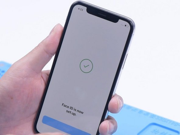
Success!