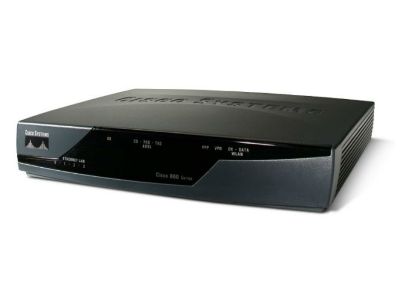
Cisco 878 Integrated Services Router Teardown
Duration: 45 minutes
Steps: 11 Steps
Step 1


Only skilled pros should handle the installation, replacement, or service of this equipment. Trust the experts for a job well done!
While working through this step, don’t forget your grounding wrist straps – they’ll help protect your gear from ESD damage. And keep your hands and any metal tools away from the backplane to avoid any unpleasant shocks!
First things first – make sure the power switch is in standby mode, and the power supply cable is unplugged. Next, disconnect all the cables from the router’s back panel. Stay cool and take your time, it’s all part of the process.
– Grab your Phillips #1 screwdriver and unscrew the two screws on the back of the device. It’s a quick and easy step—just a couple of twists and you’re on your way!
Tools Used

Step 2


– 1. Gently push the top cover of the router away from you—think of it as a little nudge.
– 2. Now, lift the top cover from the bottom of the router like you’re peeling off a sticker.
– 3. Carefully remove the top cover from the device, like you’re unveiling a surprise.
– Place the router bottom on an antistatic mat—let it rest and relax while you work.
Step 3


– Grab your Phillips #1 screwdriver and unscrew the three screws on the front of your device. It’s a quick and easy step, so no stress—let’s get this thing open!
Tools Used
Step 4


Handle those plates with care—let’s keep them nice and flat!
– 1. Carefully lift the inner metal shield from the bottom of the router. Go slow, no rush!
– 2. Gently remove the inner metal shield from the device, using the anchors as your guide (check the picture for help).
Step 5


– 1. Place your fingers on the levers found on each side of the slot, then pop them open.
– 2. Give the release lever a confident pull away from the module until it hops up.
– 3. Lift the module out of the slot—easy as pie!
Step 6

Just pop off that one silver screw – the second one is hanging on to the cooling plate, so leave it be!
– 1. Grab your Phillips #1 screwdriver and spin out the black screw.
– 2. With the same trusty tool, remove the silver screw just like you see in the photo.
Tools Used
Step 7


Handle the 4-pin connector (marked in red) with care – it’s a little delicate, so don’t go yanking it around!
– Lift the module up carefully to unplug the two connectors hanging out underneath.
Step 8

When reattaching those screws, remember: no need to muscle it! The threads are plastic, so be gentle and kind.
– Grab your Phillips #1 screwdriver and carefully remove the two screws securing the motherboard. Keep them handy for reassembly. If you need help, you can always schedule a repair.
Tools Used
Step 9


– 1. Carefully pop up the board to unlock those sneaky plastic clips.
– 2. Gently slide the board away from the back panel—this will free it from the metal shields near the connectors.
– 3. Lift the board out of the case. Nice work!
Step 10

– Let’s gather our materials:
– 1. Top cover
– 2. Inner metal shield cover
– 3. Bottom part of the case with metal shielding
– 4. Motherboard
– 5. SHDSL Filter Module board
– 6. StrataFlash Memory Module
– 7. 1 black screw, 1 silver long screw (the silver long screw is still hanging out with the SHDSL Filter Module board), and 7 silver screws
Step 11

– Locate the mini-PCI slot reserved for the WLAN card and gently lift the latch to access it. Find the DRAM socket to add more RAM Memory Module—make sure to align it properly before seating. Identify the slot designated for the extra StrataFlash Memory Module (noticing the 4MB module already in place) and carefully insert your upgrade. Lastly, find the two connectors meant for the SHDSL Filter Module board and connect them securely. If you need help, you can always schedule a repair.
Success!