DIY Acer Iconia Tab A501 Display Replacement Guide
Duration: 45 minutes
Steps: 33 Steps
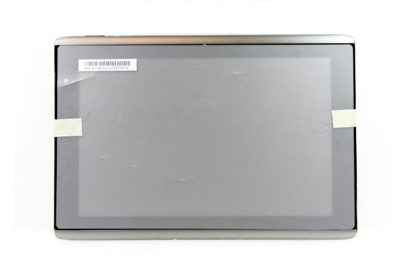
Your device’s display is the window to its soul – without it, you’re flying blind! Luckily, replacing the display on your Acer Iconia Tab A501 is a breeze with this step-by-step guide. Follow along and you’ll be back to browsing, gaming, and streaming in no time. If you need help, you can always schedule a repair.
Step 1
Make sure to power down your device before diving in.
– Let’s get started! Use a plastic opening tool to carefully pry the back cover away from the device, starting at the volume buttons – it’s time to get inside!
– Keep going! Continue to separate the back cover along the short side closest to the camera and work your way around the device. You’re making great progress!
Step 2
– Once you’ve made enough progress around the device—just a smidge more than halfway—the back cover will pop right off like a champ!
Step 3
– Peel away all the tape from your device with care. It’s time to let it breathe!
Step 4
In the next step, remember to keep a gentle touch and avoid putting too much pressure on the motherboard—let’s keep it happy and scratch-free!
– Grab those angled tweezers and gently unplug the motherboard-battery cable from the white connector located right in the center of the side opposite the docking port. You’ve got this!
Tools Used
Step 5
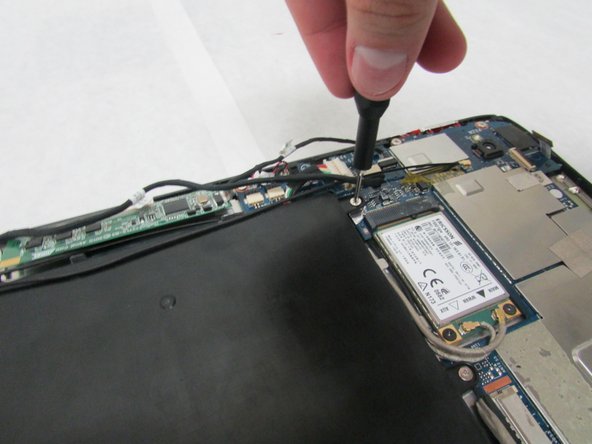
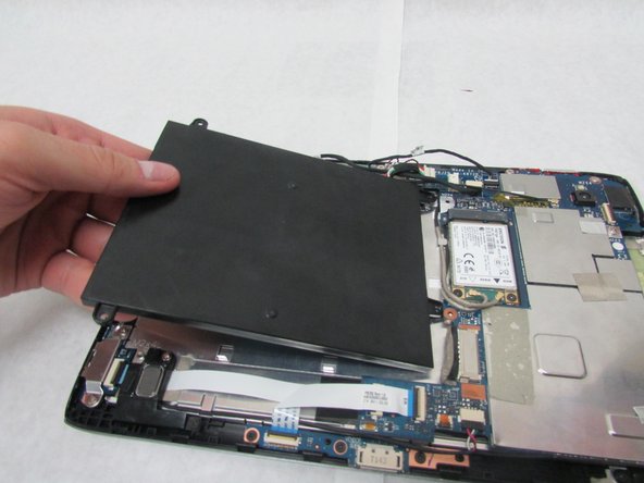
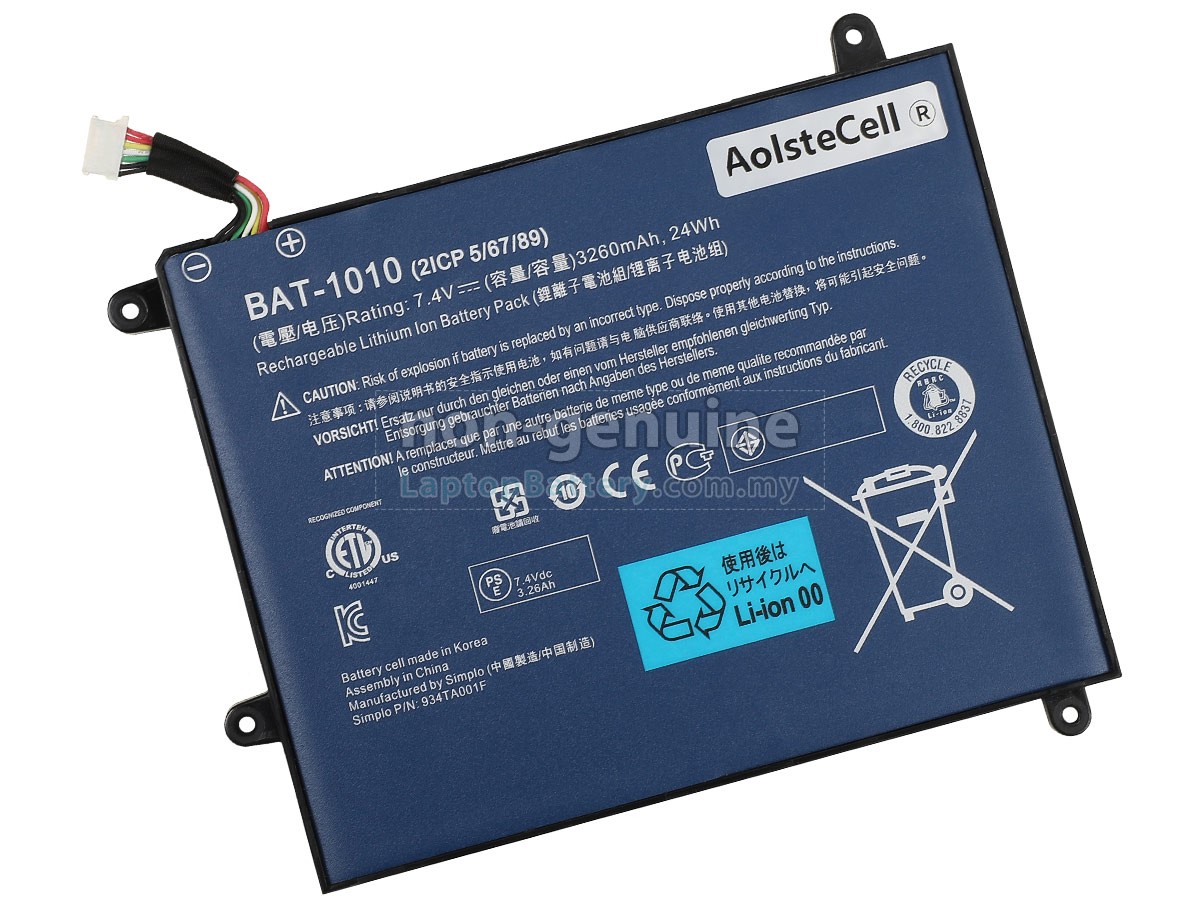
– Grab your trusty Phillips #1 screwdriver and get ready to tackle those four 4.0 mm Philips head screws that are keeping the battery snugly connected to the motherboard. Let’s unscrew them with style!
– Now, gently lift out the battery and give it a little wave goodbye. You’re one step closer to your repair victory!
Tools Used
Step 6
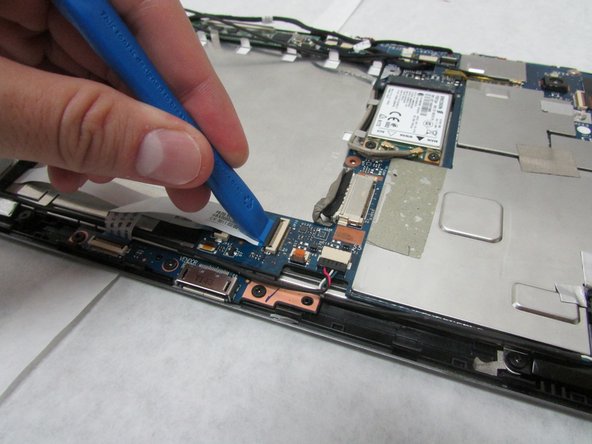
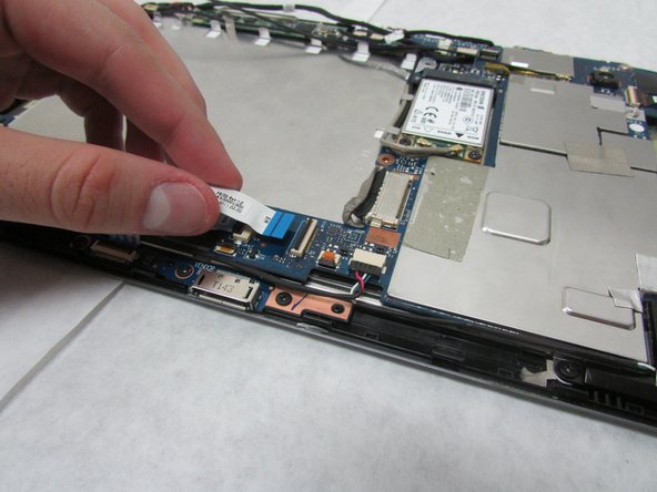
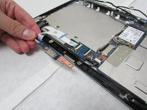
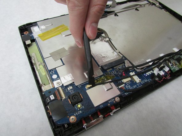
– Grab your trusty plastic opening tool and gently lift the locking mechanism on the motherboard that’s holding onto that folded, white ribbon cable.
– Now, carefully detach the folded, white cable and set it aside.
Step 7
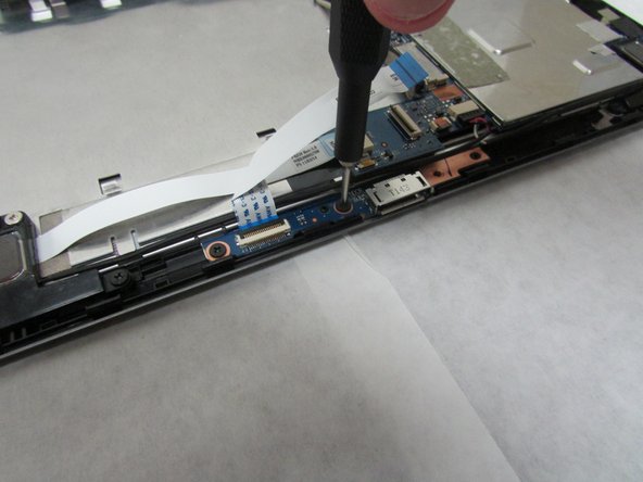
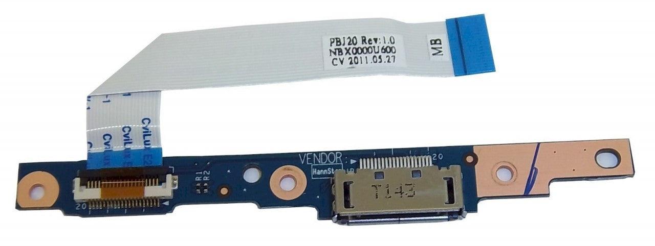
– Grab your trusty Phillips #1 screwdriver and get ready to tackle those three 3.0 mm Philips head screws that are keeping the docking port snug as a bug. Unscrew them with confidence!
– Once those screws are out of the way, gently lift out the docking port. You’re doing great!
Tools Used
Step 8
Take it easy in this step! Avoid pressing too hard or scratching that precious motherboard.
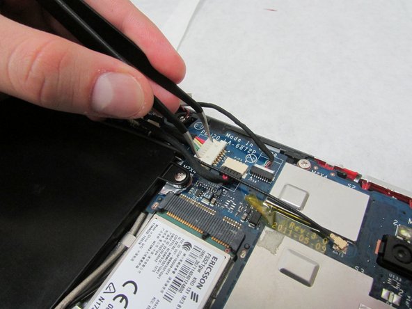
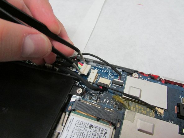
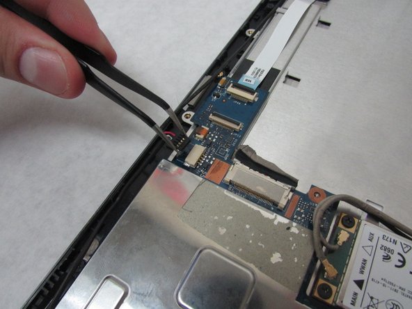
– Grab those angled tweezers and gently detach the cable with the red, white, and green wires from the beige connector that’s nestled just a bit in from the docking port. You’re doing great!
Tools Used
Step 9
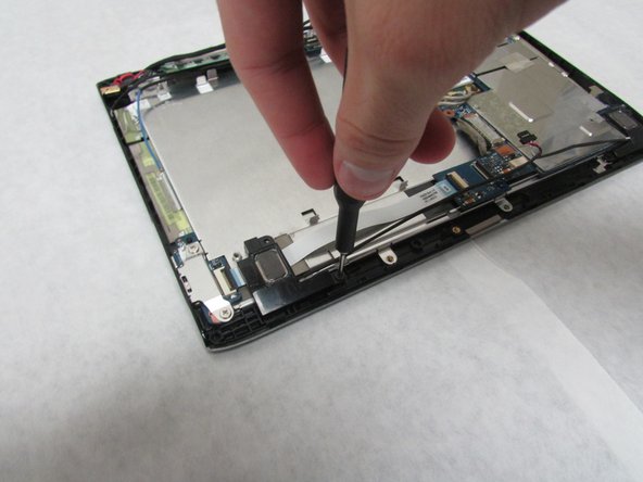
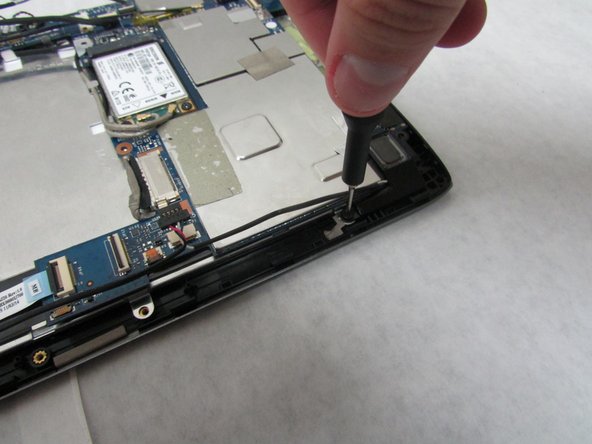
– Grab your trusty Phillips #1 screwdriver and get ready to tackle those 3.0 mm screws on each speaker. Unscrew them with a flourish!
– Now, switch it up and take on the 4.0 mm screws on each speaker. A little twist with your Phillips #1 screwdriver, and you’re golden!
Tools Used
Step 10
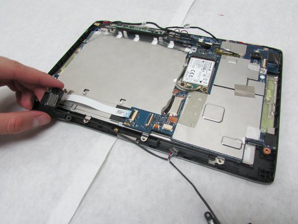
– Gently take out the speakers like you’re handling a tiny treasure.
Step 11
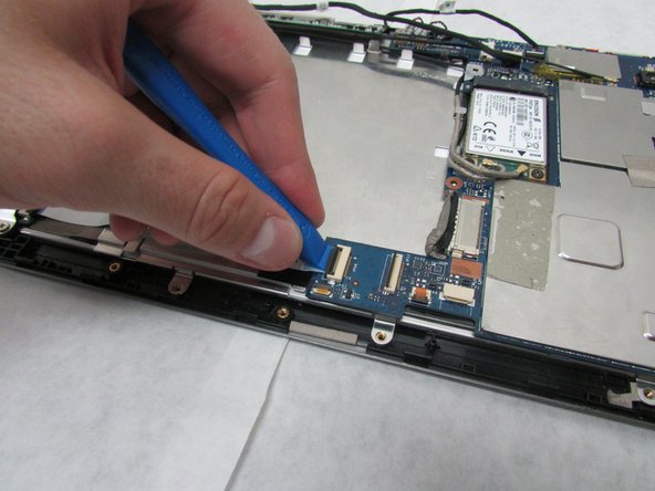
– Grab your trusty plastic opening tool and gently lift the locking mechanism on the motherboard that’s holding onto that straight, white ribbon cable.
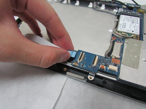
– Now, go ahead and carefully detach the straight, white ribbon cable. You’ve got this!
Step 12
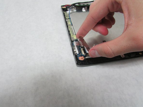
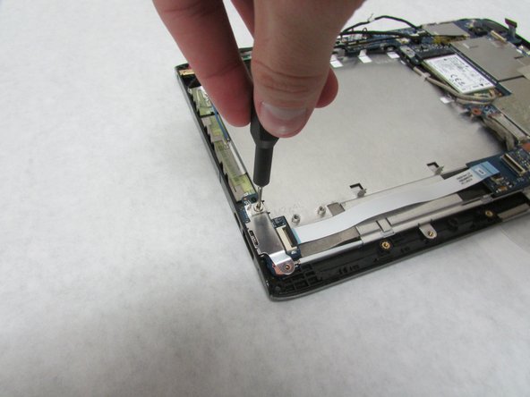
– Grab your trusty Phillips #1 screwdriver and take out those two 4.0 mm Phillips screws that are holding the metal plate, USB board, and your device together.
– Now, let’s lift off that metal plate!
Tools Used
Step 13
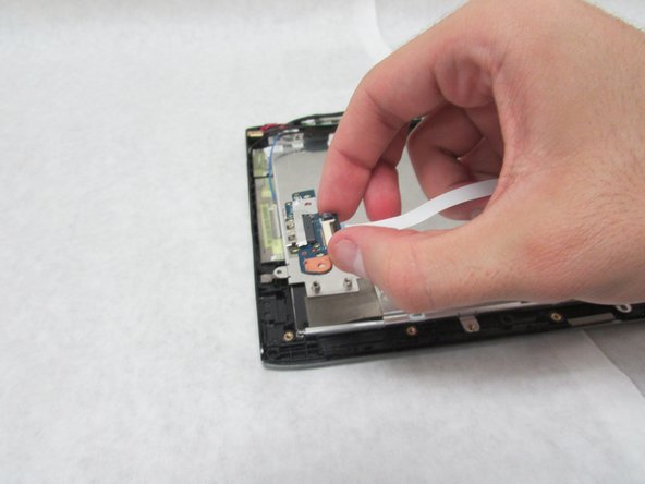
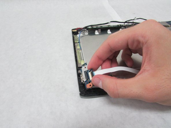
– Grab your trusty Halberd Spudger and gently nudge those ports up and out. You’ve got this!
Tools Used
Step 14
Handle this next step with a sprinkle of caution!
– Grab the wide, flat end of that trusty standard Spudger and gently pry away the display connector from the large, metal port nestled right next to the battery area. You’ve got this!
Tools Used
Step 15
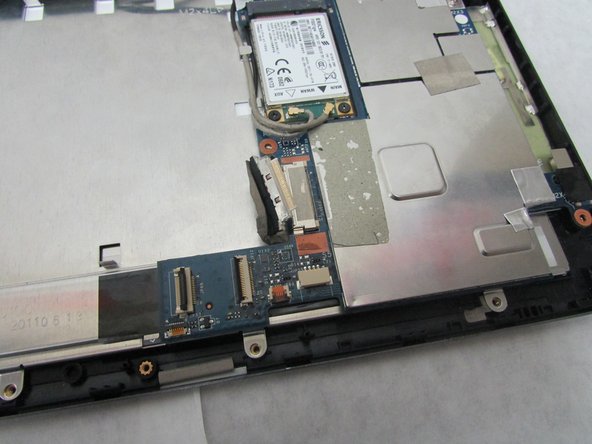
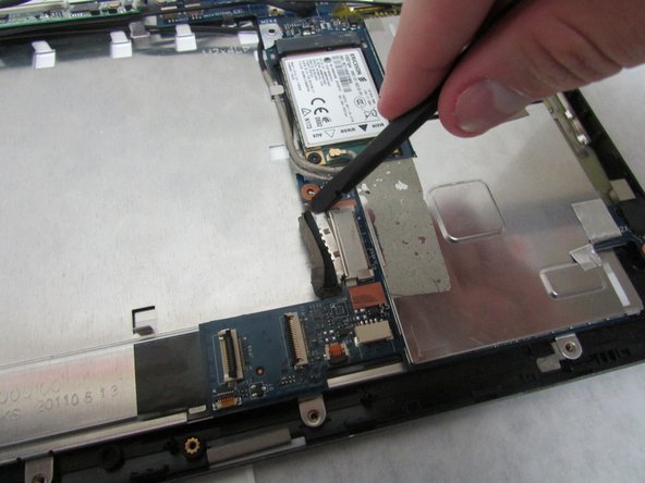
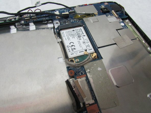
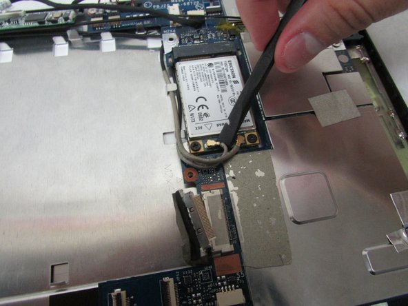
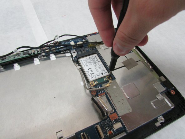
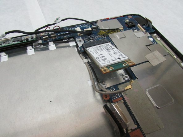
– Grab the flat end of your trusty Spudger and gently disconnect those two little, twisty connectors that are hanging out with the wireless adapter. You’ve got this!
Tools Used
Step 16
– Grab your trusty Phillips #1 screwdriver and let’s get to work! Unscrew those two 3.0 mm Philips head screws that are holding the adapter in place. You’ve got this!
Tools Used
Step 17
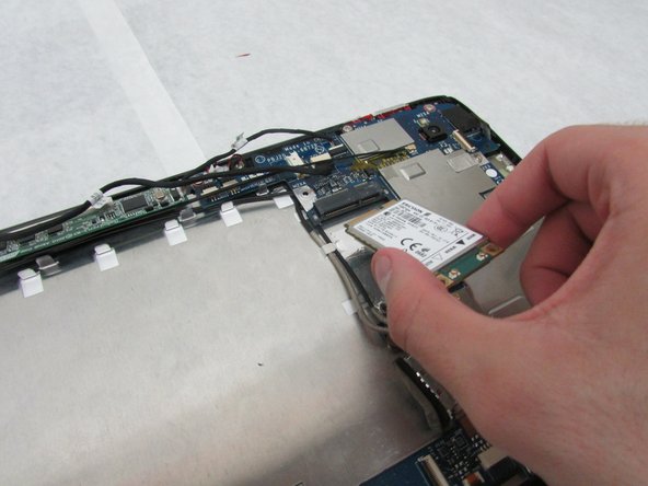
– Gently ease the adapter out to set it free.
Step 18
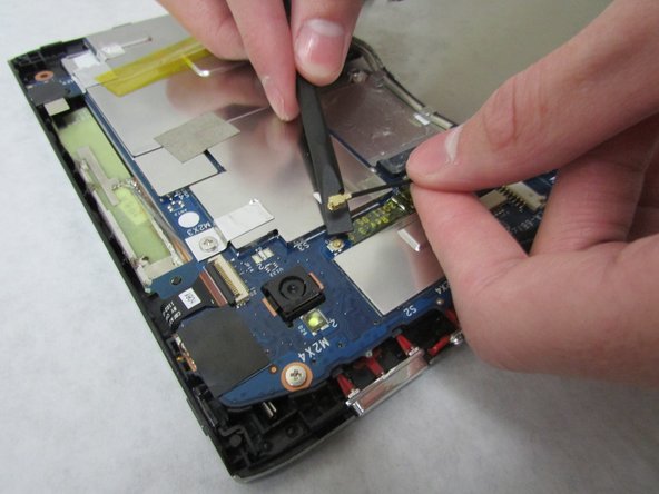
– Grab the wide end of your trusty Spudger and pop off that swivel connector linked to the 3G antenna—just below the rear camera. Easy-peasy!
Tools Used
Step 19
In the next step, remember to handle the motherboard with care—no squeezing too hard or scratching it!
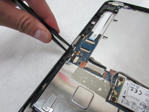
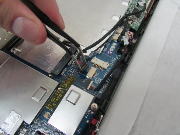
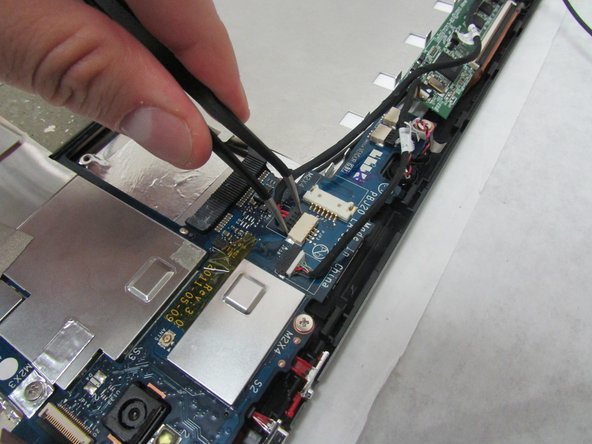
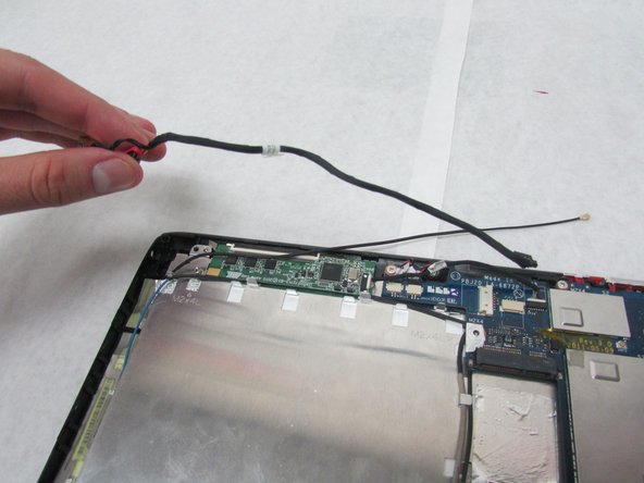
– Grab those angled tweezers and gently detach the cable with the red wires from the cozy beige connector right across from the docking port. You’ve got this!
Tools Used
Step 20
The charging port might be stuck with some tape underneath—don’t panic! A little extra oomph will help you pop it out.
– Grab those angled tweezers and gently ease out the charging port. You’ve got this!
Tools Used
Step 21
For this step, take it easy—don’t press too hard or accidentally scuff up the motherboard. You’ve got this!
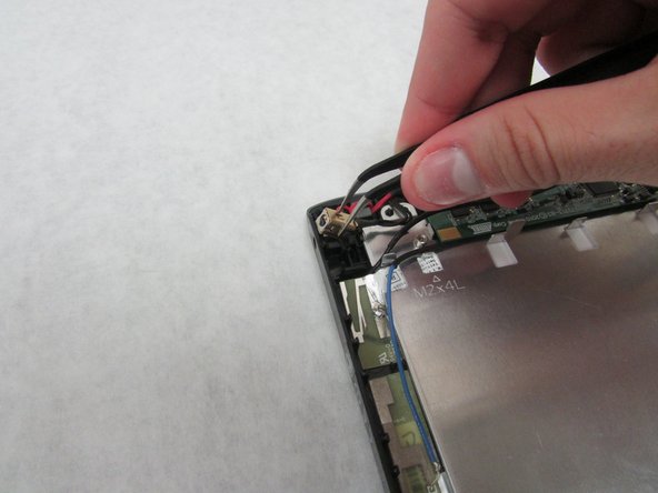
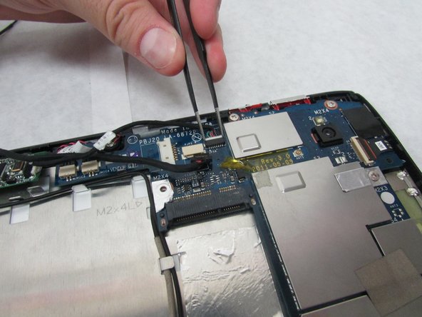
– Grab your trusty tweezers and gently lift the white touchscreen connector, which has those snazzy multi-colored wires, out of the black port located just below the power buttons on the motherboard. You’ve got this!
Tools Used
Step 22
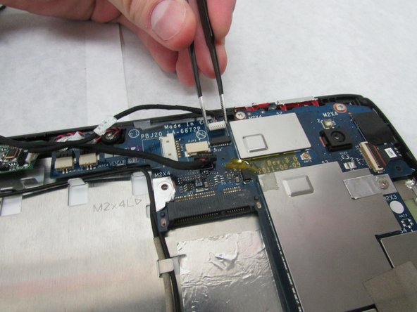
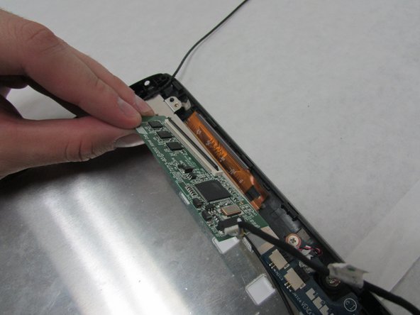
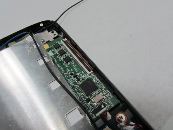
– Grab your trusty plastic opening tool and gently lift up the locking mechanism on the wide, white port that’s holding the thin, orange-brown touchscreen cable. It’s right above the charging port, so keep an eye on it.
– Carefully remove the touchscreen board. You’ve got this!
Step 23
In this step, take it easy! Avoid pressing down too hard or scratching that motherboard – treat it like the precious gem it is.
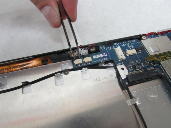
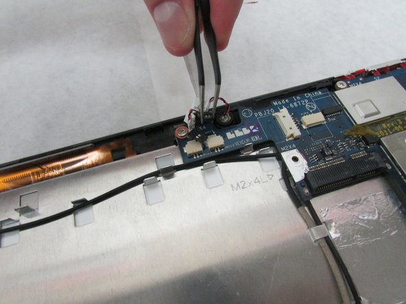
– Time to get those tweezers ready! Use the angled ones to carefully disconnect the two microphone connectors located just above the orange-brown touchscreen connector and next to the battery space. Take your time and make sure they’re completely disconnected before moving on.
Tools Used
Step 24
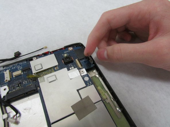
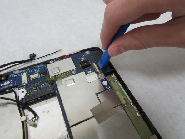
– Grab that trusty plastic opening tool and gently flip up the locking mechanism for the white front camera port, located just above the rear-facing camera. You’re doing great!
– Now, carefully disconnect the camera cable from the motherboard. You’ve got this!
Step 25
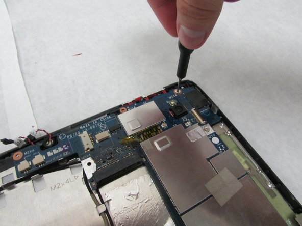
– Let’s get started! Use a trusty Phillips #1 screwdriver to carefully remove the four 4.0 mm Phillips head screws that hold the motherboard in place. This is the first step in freeing up the motherboard, and you’re doing great!
Tools Used
Step 26
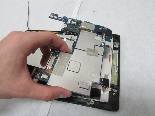
– Carefully take out the motherboard.
Step 27
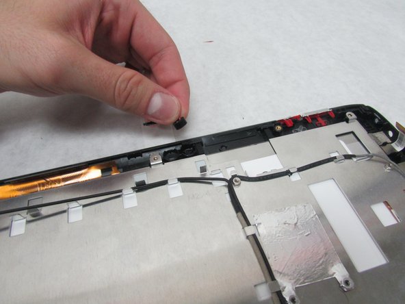
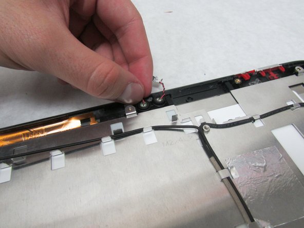
– Pop out the two microphones located in the center of the side that’s away from the docking port.
Step 28
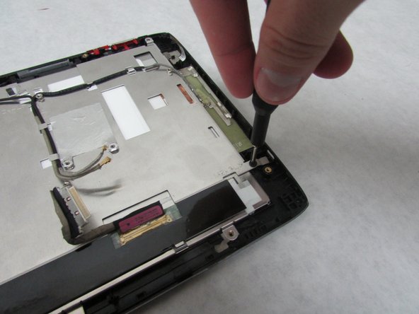
– Grab your trusty Phillips #1 screwdriver and gently twist out the 3.0 mm Phillips head screw that’s keeping the sleek metal plate in place, right by the Micro-HDMI port. You’re doing great!
– Now, let’s tackle that 4.0 mm Phillips head screw sitting near the orange-brown touchscreen cable. Just a few turns and you’ll be on your way!
Tools Used
Step 29
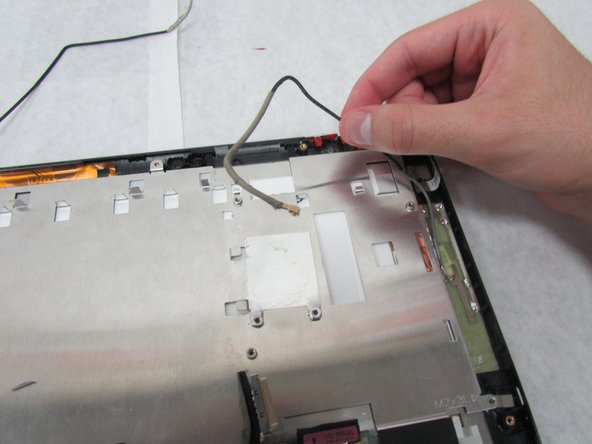
– Gently clear away all the wires from the sleek, metal plate. Let’s keep things tidy and ready for action!
Step 30
– Let’s get that metal plate off, shall we? It’s time to reveal the inner workings of your device!
Step 31
The antennae in the next step are stuck on with some serious adhesive magic.
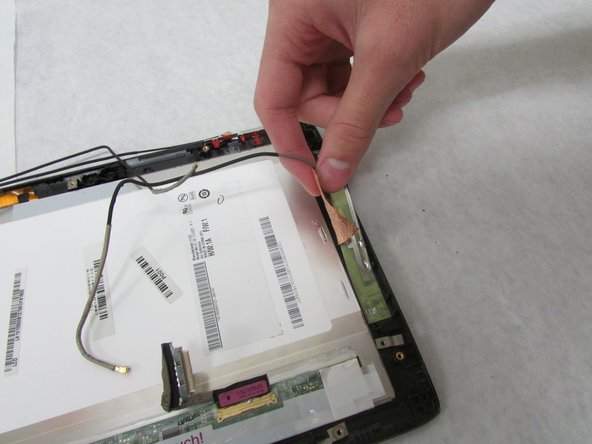
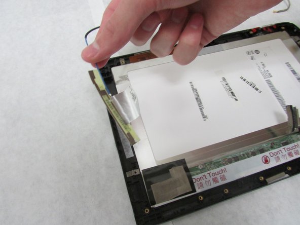
– Carefully detach the three antennae located along the shorter edges of your device. You’ve got this!
Step 32
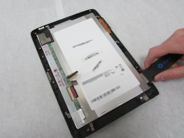
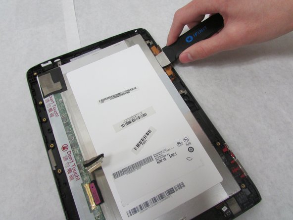
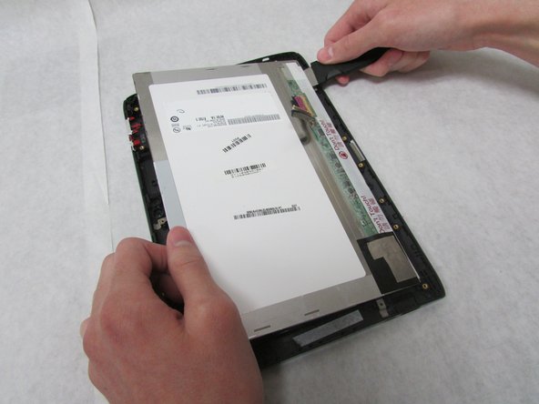
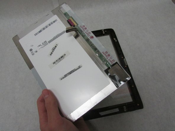
– Gently slide the Jimmy between the display and the glass to break that pesky glue seal.
– Run the Jimmy all the way around the device like you’re giving it a little hug.
Tools Used
Step 33
– Now it’s time to put your device back together! Just retrace your steps and follow these instructions in reverse. You’ve got this!
– If you need help, you can always schedule a repair
–
Tools Used
Success!
