DIY Google Pixel 3 Screen Replacement Guide
Duration: 45 minutes
Steps: 62 Steps
Hey, this repair guide is totally awesome! It was created by the repair gurus at Salvation Repair, but it’s not sponsored by Google. This guide is designed for the real deal Google screen assembly. If you need help with your repair, you can always schedule a repair.
This repair guide was put together by the Salvation Repair team and isn’t officially backed by Google. Want to know more about our repair guides? Check them out here. In this guide, we’ll walk you through replacing the screen assembly on your Google Pixel 3. We’re using a genuine Google screen assembly, which combines both the screen and the frame into one part. Before diving in, double-check that you’ve got the right part for the job. Some of the photos here are from a different model, so you might notice tiny visual differences, but don’t worry—they won’t mess with the procedure.
Step 1


– Grab your trusty SIM eject tool, a bit, or even a straightened paper clip and gently slide it into the SIM card tray hole.
– Give that SIM eject tool a little push to pop out the SIM card tray like a pro.
– Carefully pull out the SIM card tray and voilà!
Step 2

– Warm up an iOpener and press it against the bottom of your phone for a solid minute.
Tools Used

Step 3


Double-check that you’re not confusing the screen side with the back cover side. It happens to the best of us!
Avoid using metal tools for prying; they can scratch or even shatter that lovely glass back cover. If the panel is being stubborn, give it a little more heat with a hair dryer or heat gun. You’ve got this!
Got a badly cracked back cover? No worries, just slap some clear packing tape on it and the suction cup should stick like a charm.
Having trouble getting it to budge? Don’t sweat it, just apply some more heat and give it another shot. If you’re still stuck, remember that Salvation Repair is here to help – if you need help, you can always schedule a repair.
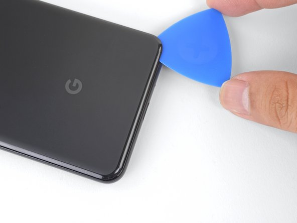
– Grab a suction cup and stick it onto the nicely warmed bottom edge of that back cover.
– Give it a firm, steady tug to open up a little gap, like magic!
– Slide an opening pick into that gap you just created and let’s keep going!
Step 4

Stay safe and savvy when inserting your opening pick above the power button – no need to go deep dive mode on the fingerprint sensor cable! If you need help, you can always schedule a repair


Step 6


The adhesive can be super sticky. Move the pick in and out like you’re sawing to make it easier. If you need help, you can always schedule a repair.
– Warm up the right edge with an iOpener and keep slicing through that adhesive with an opening pick like a pro!
Tools Used
Step 7


Be careful when slicing above the power button – don’t insert the pick more than halfway to avoid damaging that fingerprint sensor cable. If you need help, you can always schedule a repair
– Keep that heat going and slice around the rest of the phone’s edges. Pop a pick into each corner to stop the adhesive from sticking back together. You’re doing great!
Step 8


Hey there! Just a friendly reminder, don’t try to pry off that back cover just yet. It’s still hanging on with the fingerprint sensor cable, and we wouldn’t want any mishaps!
– Alright, now that you’ve scored around the perimeter of the phone, gently lift the left edge of the back cover.
– Go ahead and flip the back cover along its long side, making sure the fingerprint sensor cable isn’t being stretched. You’re doing great!
Step 9

– First things first, let’s get those two 4.1 mm-long Phillips screws out of the way that are holding the fingerprint connector bracket in place.
– As you tackle this repair, remember to keep a close eye on each screw – they all want to return home to the exact spot they came from!
– When you’re putting things back together, take it easy on the tightening; we don’t want to end up with a display that’s seen better days.


Step 11


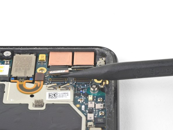
When you’re unplugging connectors like these, just take a moment to be gentle and avoid knocking loose those tiny surface-mounted components hanging out around the socket. You’ve got this!
– Use the tip of your spudger to gently lift and disconnect the fingerprint connector from its socket. It’s like giving it a little high five!
– To reconnect this connector, line up the sides and press down on one side until you hear a satisfying click. Then repeat on the other side. Don’t press down on the middle – that could bend the pins and cause trouble. If you need help, you can always schedule a repair.
Tools Used
Step 12


– First up, let’s get that back cover off! It’s time to reveal the inner workings of your device.
– Before you slap on a shiny new back cover, make sure to banish any leftover adhesive from the phone frame. Grab an opening tool and a bit of high concentration isopropyl alcohol to give that surface a good scrub.
– If you’re giving your back cover a second chance, make sure to clean off any old adhesive and apply some fresh back cover adhesive to keep it secure.
– If you’re swapping in a replacement back cover, take a moment to compare it with the original. Don’t forget to transfer any little parts like the flash diffuser over to the newcomer!
– Check out this guide for a step-by-step on how to apply that new back cover adhesive like a pro.
Tools Used

Step 13

– Unscrew the five Phillips screws holding the wireless charging coil in place:
– Two 1.9 mm screws – easy peasy
– Two 4.2 mm screws – don’t forget these!
– One 4.3 mm screw – this one’s the oddball, but still no sweat

Step 15


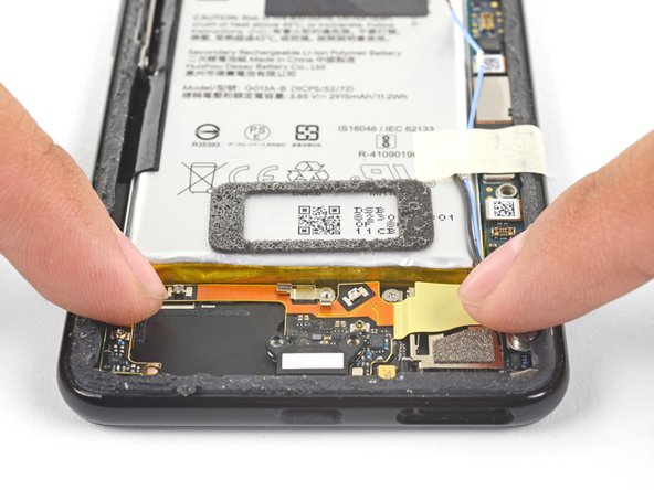
– Let’s get started by using the point of a spudger to carefully pry up and disconnect the battery press connector from its socket, which you’ll find near the right edge of the phone. If you need help, you can always schedule a repair
Tools Used
Step 16


When it’s time to remove those standoff screws, a standoff bit is your best bet. If you don’t have one handy, a small flathead screwdriver can get the job done – just be super careful not to slip and damage the surrounding components. If you need help, you can always schedule a repair
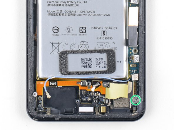
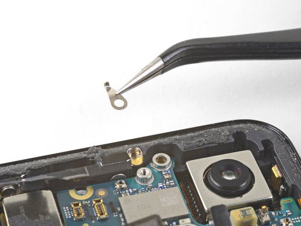
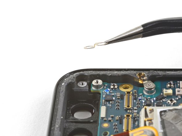
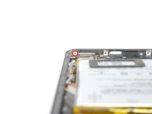
– First up, let’s tackle those two screws holding the camera bracket in place: unscrew them away!
– Once that’s done, go ahead and lift off the camera bracket with care.
– Grab your trusty 4.1 mm Phillips screw and set it aside.
– Don’t forget about that 4 mm standoff screw; it’s just as important!
Step 17

Hey there! Time to choose the right camera to swap out. If you’re swapping front cameras, decide which one you need to replace. If you’re doing the motherboard removal, be ready to say goodbye to both cameras! Remember, if you need a hand, you can always schedule a repair!
– Regular view camera
– Wide-angle lens


Step 19


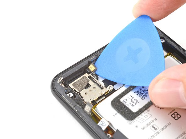
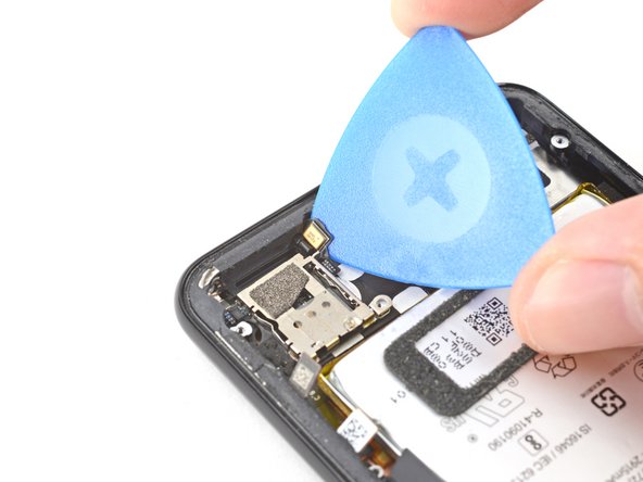
The cameras are secured in place with some adhesive. A little stickiness, but nothing you can’t handle!
– Now, let’s loosen that camera module. Grab your trusty spudger and gently slide the tip under the edge of the camera module. Give it a little pry, like you’re opening a treasure chest, and it should pop loose from the frame. If you need help, you can always schedule a repair.
Tools Used
Step 20

– Grab a pair of blunt nose tweezers and gently lift out the camera(s).
– If the adhesive holding the camera module is still doing its job, feel free to reuse it! If not, no worries—just swap it out for some trusty double-sided Tesa tape.
– When you’re ready to pop in that shiny new camera module, double-check that the lens area of the phone frame is clean and free from any sticky residue or debris.
Tools Used

Step 21

Easy peasy, just be careful when using the spudger, you don’t want to poke that battery! If you need help, you can always schedule a repair.
– Time to get that loudspeaker connected – use the pointy end of a spudger to carefully pry up and disconnect the loudspeaker connector from its socket on the motherboard, which you’ll find near the right edge of your phone. If you need help, you can always schedule a repair
Tools Used
Step 22


Don’t forget to pop that insert back in before securing the daughterboard with screws!
– Alright folks, let’s get your device singing ‘I’m alive’ again! First off, take a screwdriver and unscrew the four little buddies – don’t lose the tiny grounding clip, it’s like the guardian of your device’s motherboard. Next, gently slide out the decorative plastic piece from that USB-C port. Now, we’ve got five screws: two 1.9mm, two 4.3mm with thinner shanks, and one plain old 4.3mm colleague. Once that’s done, you’ll see the mother circuit board! Reassembly’s a snap, just like a friendly puzzle.You got this! If you’re ever in a pickle, remember, you can always schedule a repair with our tech wizards.
Step 23


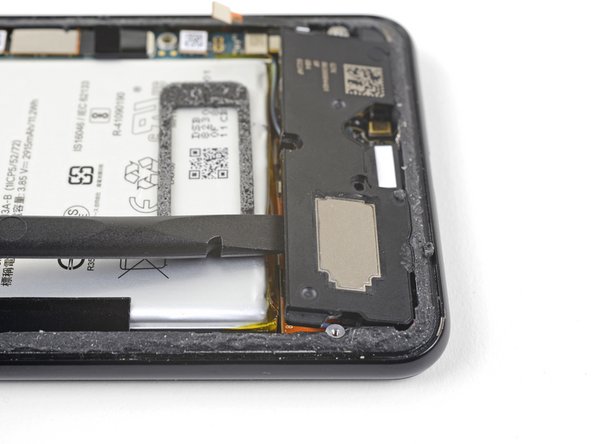
The loudspeaker is still firmly stuck in place with a tough adhesive gasket. Before trying to remove it, gently work your way around it and break the seal in a few spots to loosen it up.
– Gently slide the tip of a spudger under the bottom right corner of the loudspeaker.
– Give it a little pry to help loosen the loudspeaker from its cozy spot in the phone.
Tools Used
Step 24


– Let’s get that speaker out! Gently slide the tip of your spudger under the top left corner of the speaker.
– Now, carefully pry up to loosen the speaker. It’s like giving it a little hug, but with a tool!
Tools Used

Step 26


– Let’s get started by removing the loudspeaker – it’s the first step to getting your device sounding great again.
– Before you put in a new loudspeaker, take a look at the adhesive gasket. If it’s still in good shape, you can reuse it – just make sure it’s not covering the exit hole.
– If the gasket has been pulled out of place, don’t worry – just remove it and replace the adhesive with a pre-cut strip or some Tesa tape. Easy peasy!
– If you’re not feeling confident about this step, or any other part of the process, don’t hesitate to schedule a repair with Salvation Repair – we’re here to help.


Step 28


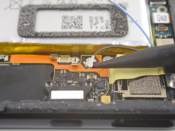
Be gentle with that cable – it’s a bit of a fragile friend. If it feels stuck, try using the point of a spudger to coax the clip open just a little, then give it another shot. And remember, if you need help, you can always schedule a repair
– Gently use the tip of a spudger to lift and free the blue antenna cable from its grounding clips. You’ve got this!
Tools Used
Step 29

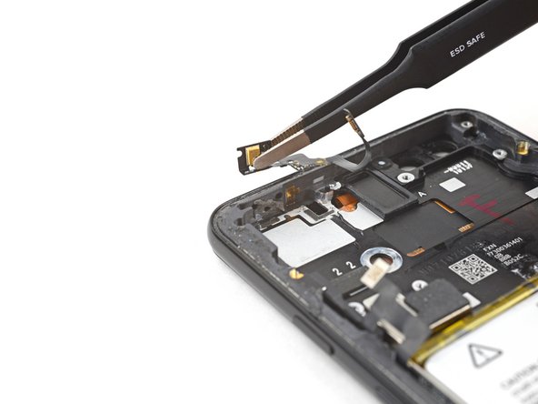
– Grab your trusty spudger and gently nudge up that black antenna cable from its socket by the USB-C port. It’s like giving it a little high-five to say, ‘You’re free!’
Tools Used
Step 30

– Gently guide those antenna cables away from the charging assembly, making sure they’re not tangled up in anything. You’ve got this!
Step 31


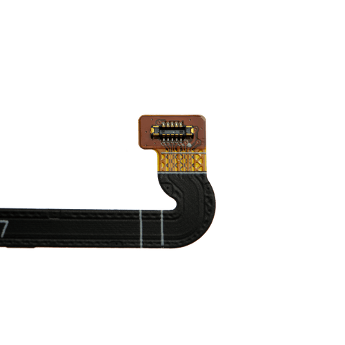
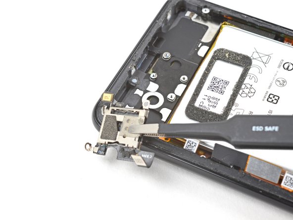
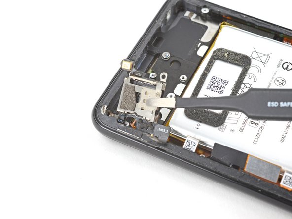
– Grab your trusty spudger and gently nudge the charging assembly connector away from its cozy home on the motherboard, located near the right edge of the phone.
– Carefully peel back the flex cable from the top of the SIM card reader like you’re unwrapping a present—slow and steady wins the race!
Tools Used
Step 32


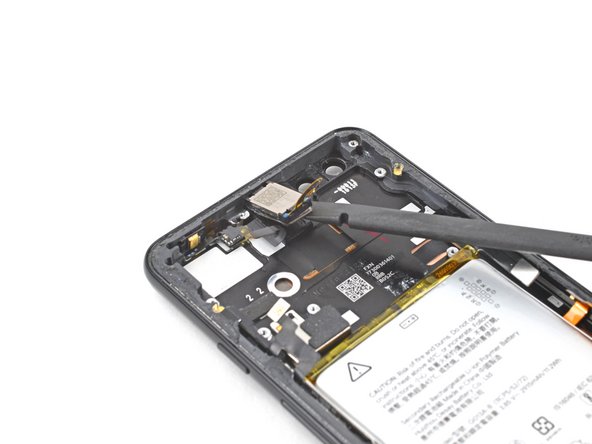
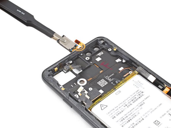
Avoid using metal tools to pry; they might just take a liking to the flex cable and cause some damage. Let’s keep things smooth and safe!
– Now, let’s get that display flex cable out of there! Use the flat end of a spudger to carefully pry up the black tape holding it in place, near the right edge of the phone.
– Time to disconnect that display connector! Use the flat end of your spudger to gently pry it up and separate it from the motherboard. You got this!
Tools Used
Step 33

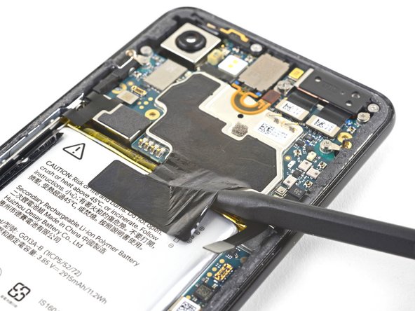

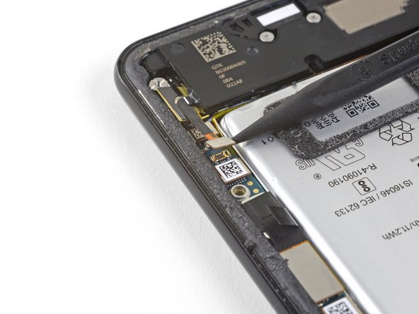
Be careful when using the spudger near the battery – we don’t want any accidental punctures. If you’re not comfortable with this step, don’t worry, you can always schedule a repair
– Gently slide the tip of a spudger into the gap beneath the black tape that connects the battery to the motherboard.
– Carefully glide the spudger along this gap to lift the tape away from the battery side.
– With a steady hand, peel the tape off the battery and fold it out of your way.
Tools Used
Step 34

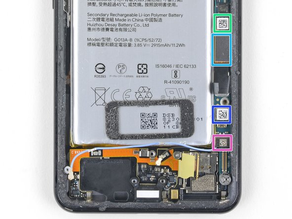
– Grab your trusty spudger and let’s get to work! Carefully pry up and disconnect these seven press-fit connectors from their cozy spots on the motherboard:
– External buttons connector
– Top microphone connector
– Earpiece connector
– Left squeeze sensor connector
– Screen connector
– Right squeeze sensor connector
– SIM tray connector
Tools Used
Step 35

– Time to give that earpiece speaker flex cable a little lift! Using the flat side of your spudger, carefully pry up the cable and bend it gently upwards, so it’s out of the way of the motherboard.
Tools Used
Step 36

Keep an eye on those tiny grounding clips as you remove the screws – they’re easy to lose, but important to keep track of.
For standoff screws, a standoff bit is your best bet. If you don’t have one, a small flathead screwdriver will work in a pinch, but be careful not to slip and damage the surrounding components. If you’re not feeling confident, don’t worry – you can always schedule a repair with Salvation Repair.
– Let’s get started by taking out the six screws that are holding the motherboard snugly in place:
– Don’t forget to carefully remove and keep the three small metal grounding clips safe.
– One 4.2 mm Phillips screw
– Three 1.9 mm Phillips screws
– One 4.3 mm Phillips screw
– One 3.83 mm standoff screw
Step 37

– Alrighty, it’s time for a little phone makeunder, but don’t stress, we gotchu! First, you’ll wanna gently wiggle that antenna bracket right off the top left corner. Next up, we’ve got a mini mission to reinstall those teeny-tiny metal grounding clips. Just line ’em up so the shiny side is facing skyward and their pointy bits are aiming towards the edge. Whichever one’s got those cute teardrop shapes, make sure their pointed ends are looking at the edge too, and hey, that last clip’s design is hella unique, so it dips down near the top right screw hole. If you’re feeling kinda lost, no worries,ätz just give our friendly repair squad a shout and they’ll hook you right up! So, whatcha say, ready to tackle this repairs like a boss?!
Step 38


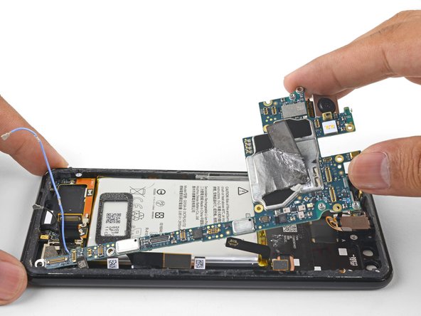
– Hey there! Time to rock ‘n’ roll with this repair. So you’ve got our back with that spudger, right? Now stand tall and gently pop the top left corner of the motherboard near the rear-facing camera – it’s like unwrapping a secret compartment. Next, spread those flex cables, kinda like the wave at the beach! Check real quick for any sneaky screws or cables still hitching a ride. That’s a wrap, my friend! If you need help, you can always schedule a repair with us, we’re the cool crew on the block!
Tools Used
Step 39


The earpiece speaker’s flex cable is going to hug the motherboard pretty closely. Just take a deep breath and gently maneuver the motherboard around that flex cable like a pro.
– Slide the spudger under the top edge of the motherboard and gently pry it up to loosen it. You’ve got this!
Tools Used
Step 40


– Gently lift the left side of the motherboard and carefully tilt it upwards toward the right. If any connectors are getting in the way, give them a little nudge to move them aside.
Step 41
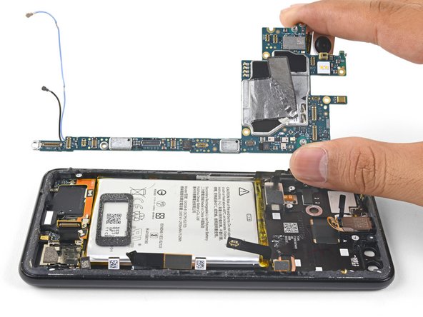

– Carefully pry the top end of the motherboard away from the frame – it’s like gently rocking a stubborn jar lid.
– Next, completely remove the motherboard from the device.
– When you’re ready to put everything back together, be mindful of those tiny flex cable connectors and make sure they’re not trapped under the motherboard.
– If the earpiece flex cable is giving you trouble, don’t stress. You can carefully lift the earpiece speaker, slide the motherboard into place, and then put the speaker back where it belongs. If you need help, you can always schedule a repair
Step 42

– Take out the two 1.9 mm Phillips screws holding the charging assembly to the phone’s bottom edge. If you need help, you can always schedule a repair

Step 44

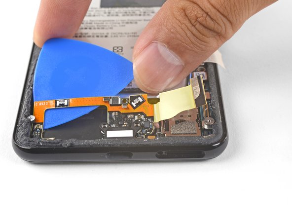
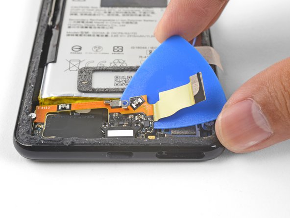
– Slip an opening pick under the charging assembly’s flex cable.
– Guide the pick beneath the charging assembly to gently loosen it from the phone.

Step 46
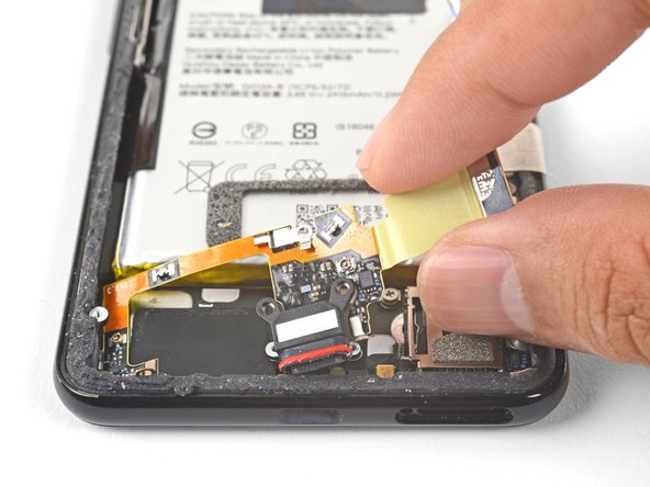

– Get ready to install that snazzy replacement assembly!
– First things first, make sure to peel off all those plastic liners from the assembly to reveal the sticky adhesive underneath.
– Now, gently position the bottom left corner of the assembly into place.
– Carefully lay down the rest of the assembly, ensuring that the USB-C port is snugly nestled in its designated cutout.
– Using your fingers, firmly press the assembly onto the frame, giving it that nice secure fit.
Step 47

– Grab your trusty Phillips screwdriver and gently unscrew those two 1.9 mm screws holding the SIM card reader in place. You’ve got this!
Step 48

Don’t forget to pop out that SIM card tray before diving into the disassembly! It’s a small step that makes a big difference.
The SIM card reader is just a little stuck to the frame, so give it a gentle nudge to free it up.
– Let’s get started by warming up that device. Heat an iOpener and apply it to the bottom right of your device for about two minutes. If you need help, you can always schedule a repair
Tools Used
Step 49

– Pop an opening pick between the frame and the lower mic module.
– Give it a little lift with the pick to loosen that adhesive.
Step 50


– Give that SIM card reader a little spin with the pick all around its edges to break free the adhesive holding it in place.

Step 52

You’re doing great! The little music maker on the phone, the earpiece, is just lightly stuck to its frame. No biggie, and you’re almost done. If you need help, you can always schedule a repair.
– Warm up that iOpener and give the top edge of your device a little love for two minutes.
Tools Used
Step 53

– Time to get started – carefully insert the flat end of your trusty spudger between the earpiece speaker and the frame, making sure not to damage any surrounding components.
– Now, gently pry up with the spudger to loosen the adhesive, taking your time to avoid any accidents.
– Almost there – remove the earpiece speaker, and you’re one step closer to a successful repair. If you need help, you can always schedule a repair
Tools Used

Step 55


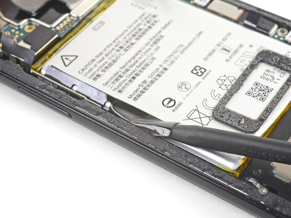
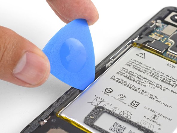
– Gently work a halberd spudger or an opening pick into the gap between the microphone assembly and the frame’s edge. You’re making great progress!
– Now, carefully slide the spudger down and pry the adhesive away from the battery. If you need help, you can always schedule a repair
Tools Used


Step 57

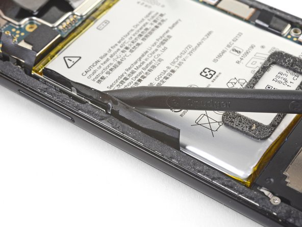
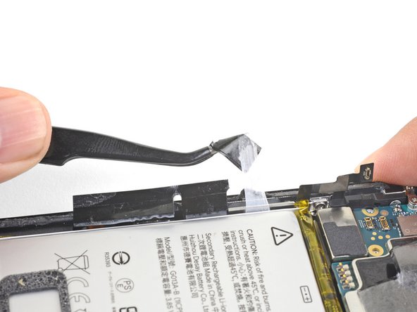
Now, here’s a fun part – gently remove the battery! These little fella’s are stuck on with some stretchy adhesive. Usually, you can give the black pull tab a tug and yank out all three at once, but it’s usually easier if you’re new to this to carefully clip where the tab gets a little notched, and remove each one individually. If you need help, you can always schedule a repair!
Tools Used
Step 58

We can also give those battery adhesives a little pep talk by adding some high concentration isopropyl alcohol. Just fill a plastic dropper or syringe and give the left edge of the battery a few drops. Let that alcohol work its magic for a minute, and it’ll loosen things right up. If you’re feeling stuck, remember, you can always schedule a repair with us!