DIY Google Pixel 4 XL Rear Camera Replacement
Duration: 45 minutes
Steps: 41 Steps
This repair guide comes straight from the talented folks at Salvation Repair and isn’t officially backed by Google.
Heads up:
Hey there, tech enthusiast! This handy-dandy repair guide will show you how to swap out or remove the rear-facing cameras on your Google Pixel 4 XL. It’s like giving your phone a brand new set of peepers. Just a heads-up: Google warns that messing with the front laser assembly can lead to some invisible infrared laser beams, so be careful. If you need help, you can always schedule a repair.
Step 1
– Ready to free your SIM card? Grab a SIM eject tool, a tiny screwdriver, or even a straightened paperclip and pop it into the little hole on the SIM card tray. It’s on the left side of your phone.
– Give it a gentle push and watch the tray slide out.
– Now, you’re ready to remove the SIM card tray. You’ve got this!
Step 2
You can also use a hair dryer, heat gun, or hot plate—but let’s keep it cool! Avoid overheating your phone, as the display and internal battery are sensitive to heat. Remember, if things get too tricky, you can always schedule a repair.
– Grab your trusty iOpener and give it a warm hug against the bottom edge of the back panel for a solid minute. Let that heat work its magic!
Tools Used
Step 3
If your back glass is looking a bit worse for wear with some serious cracks, don’t fret! Slapping on a layer of clear packing tape can help the suction cup stick like a champ. If you’re feeling adventurous, you can also try using some super strong tape instead of the suction cup. And if you’re really in a bind, a little superglue on the suction cup can do the trick to hold it onto the broken panel. Remember, if you need help, you can always schedule a repair.
– Press a suction cup onto the warmed edge of the back panel, making sure to press down firmly to create a good seal. Try to place it as close to the edge as you can for the best grip!
Step 4
Hey, depending on your phone’s age, this might be a little tricky. If you’re struggling, just give that edge a little more heat and try again. No worries, we’ve all been there! If you need help, you can always schedule a repair.
– Get a grip on that suction cup and pull up with some serious strength to create a gap between the back panel and the frame – you got this!
– Now, take your trusty opening pick and slide it into the gap you just made. If you need help, you can always schedule a repair
Step 5
– Now it’s time to get that adhesive loosened up – gently slide the opening pick across the bottom of your device towards the left corner to break through the sticky stuff.
– Keep that pick in place and slide it from the bottom left corner over to the bottom right corner – this will help you completely slice through the adhesive on the bottom side.
– Leave the pick right where it is, stuck in the bottom right corner, to prevent that adhesive from re-sealing and making your job harder. If you need help, you can always schedule a repair
Step 6
– Grab your trusty iOpener and gently place it on the left edge of the phone. Give it a minute to work its magic.
Tools Used
Step 7
– Now it’s time to get underneath that back panel – insert a second opening pick right above the charge port and get ready to make some progress!
– Gently slide that opening pick down to the bottom left corner of your phone, you’re doing great! If you need help, you can always schedule a repair
Step 8
This sticky stuff can be a real pain, but don’t worry, we got this! Just gently wiggle the pick back and forth, like you’re sawing through a giant gummy bear. It’ll loosen things up in no time. If you need a helping hand, you can always schedule a repair
– Gently work the opening pick around the bottom left corner and along the left side of the phone to carefully cut through the adhesive. Take your time and be patient!
– When you reach the top left corner, near the camera, stop and leave the pick in place. You’re making great progress! If you need help, you can always schedule a repair
Step 9
– Get your trusty iOpener nice and toasty and press it against the right edge of your phone for a whole minute. You got this!
Tools Used
Step 10
– Now that you’ve got two opening picks in place, it’s time to bring in the third pick to help with the lower part of the righthand side.
– Gently slide the opening pick upwards towards the top of the phone, carefully cutting through the adhesive on the right side.
– Stop when you reach the top right corner and leave the pick inserted – you’re making great progress! If you need help, you can always schedule a repair.
Step 11
– Gently glide the third opening pick around the top right corner and across the top edge of your phone, effortlessly cutting through that last stubborn strip of adhesive.
Step 12
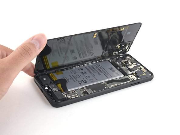
– After you’ve made your way around the edge of the phone with your trusty tool, gently lift the right side of the back cover, just like flipping open a book.
– Hold on there! Don’t yank the panel off just yet; it’s still hanging on to the phone for dear life.
Step 13
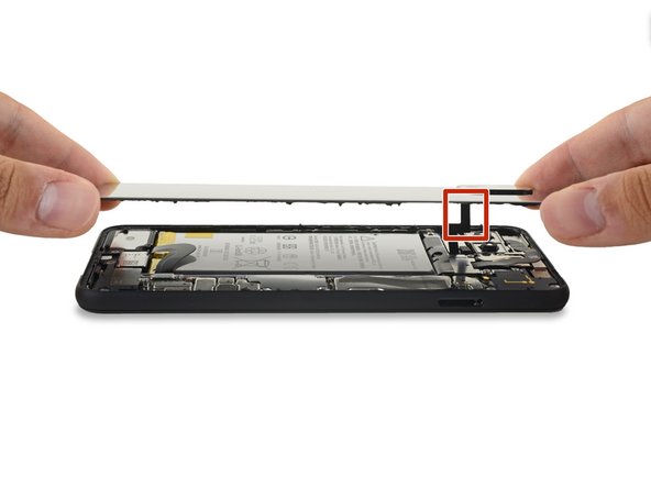
– Swing that back panel open like a pro until it can rest on the left edge of your phone. Just make sure to treat that attached ribbon cable like a delicate flower—no stress allowed!
– Now’s a perfect time to power on your phone and give all the functions a test run before you seal everything up. Just remember to turn it off completely before diving back into the repairs!
Step 14
Keep it together – literally! During this repair, make sure to keep track of each screw and return it to its original spot. If you need help, you can always schedule a repair
– Let’s unscrew those four T3 Torx screws holding down the battery connector shield:
– One 1.8 mm screw
– One 4.1 mm screw
– One 4.4 mm shouldered screw
– One 4.0 mm shouldered screw
Step 15
– Time to get a little handy! Use a trusty pair of tweezers to carefully remove the battery connector shield. If you need help, you can always schedule a repair
Tools Used
Step 16
Be careful when using the spudger near the battery – we don’t want any accidental punctures! If you’re not comfortable with this step, don’t worry, you can always schedule a repair
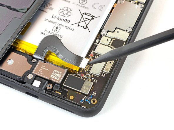
– Time to disconnect the battery! Use the pointy end of your spudger to gently lift the battery connector straight up from the motherboard. This will disconnect the battery and keep things safe.
– Now, to reconnect the connector, get it lined up perfectly and press down on one side until you hear a click. Then, do the same thing on the other side. Don’t press in the middle – we don’t want to bend any pins. If you need help, you can always schedule a repair.
Tools Used
Step 18
– Grab your trusty T3 Torx driver and carefully unscrew those two 4.1 mm screws holding down the back panel connector cover. You’ve got this!
Step 21
– Let’s get started by taking off the back panel. It’s like opening a present, but way cooler!
– When you’re putting everything back together, just follow this guide to stick on those custom-cut adhesives like a pro.
– If you’re using a pre-cut adhesive card, this guide has got your back. Just follow along!
Step 23
– Let’s kick things off! First, carefully unscrew those three T3 Torx screws that are holding down the rear-facing camera connector cover:
– One 2.7 mm screw
– One 4.1 mm screw
– One 4.2 mm screw
Step 25
– Let’s get started by unscrewing the three T3 Torx screws that are keeping the front-facing camera connector cover in place:
– First up, there’s one 4.1 mm screw waiting to be removed.
– Next, you’ll find one 4.0 mm shouldered screw that needs your attention.
– And finally, don’t forget about that last 4.1 mm shouldered screw—it’s just as important!
Step 27
– Grab a spudger and gently lift the camera and sensor connectors straight up from the motherboard. If you need help, you can always schedule a repair
Tools Used
Step 28
This cable is stuck down with some light adhesive. Don’t worry, it’s just a little sticky friend! We’ll get it loose without a fuss.
– Unplug that extra sensor connector and give yourself a high five for taking this step!
Step 29
– Alright, let’s get this camera lens out of the way! Go ahead and remove these three T3 Torx screws holding it in place. You’ll see two smaller ones at 2.7 mm each, and then a slightly bigger one at 3.1 mm.
– If you need help, you can always schedule a repair
Step 30
– Time to get up close and personal with your device’s front camera and sensor assembly – use a trusty pair of tweezers to carefully remove it. If you need help, you can always schedule a repair
Tools Used
Step 31
– Grab your trusty T3 Torx driver and let’s tackle those four 3.5 mm screws holding down the display connector cover. You’ve got this!
Step 33
– Grab your trusty spudger and use the flat end to gently disconnect the display connector from the motherboard. It’s like giving your device a little hug, but with a tool instead!
Tools Used
Step 34
– Use your T3 Torx driver to unscrew that 2.7 mm screw holding the motherboard to the frame. You’re almost there!
Step 35
– Grab your trusty spudger and gently use the pointed end to unplug the side buttons connector from the motherboard. You’ve got this!
– Next up, it’s time to disconnect those two rear-facing camera connectors from the motherboard. Just a little wiggle and they’ll be free!
Tools Used
Step 36
– Time to give that earpiece speaker connector a little break from the motherboard. Just gently disconnect it.
Step 37
– Let’s get those grip sensor connectors off the motherboard. Just wiggle them free with some care!
– Now, it’s time to detach the charge port connector from the motherboard. A little tug should do the trick!
Step 38
– Grab that spudger and gently lift the pointed end to pop off the top antenna connector from the motherboard. It’s like giving it a little hug to help it let go!
– Now, go ahead and disconnect the bottom antenna connector. You’re making great progress!
Tools Used
Step 39
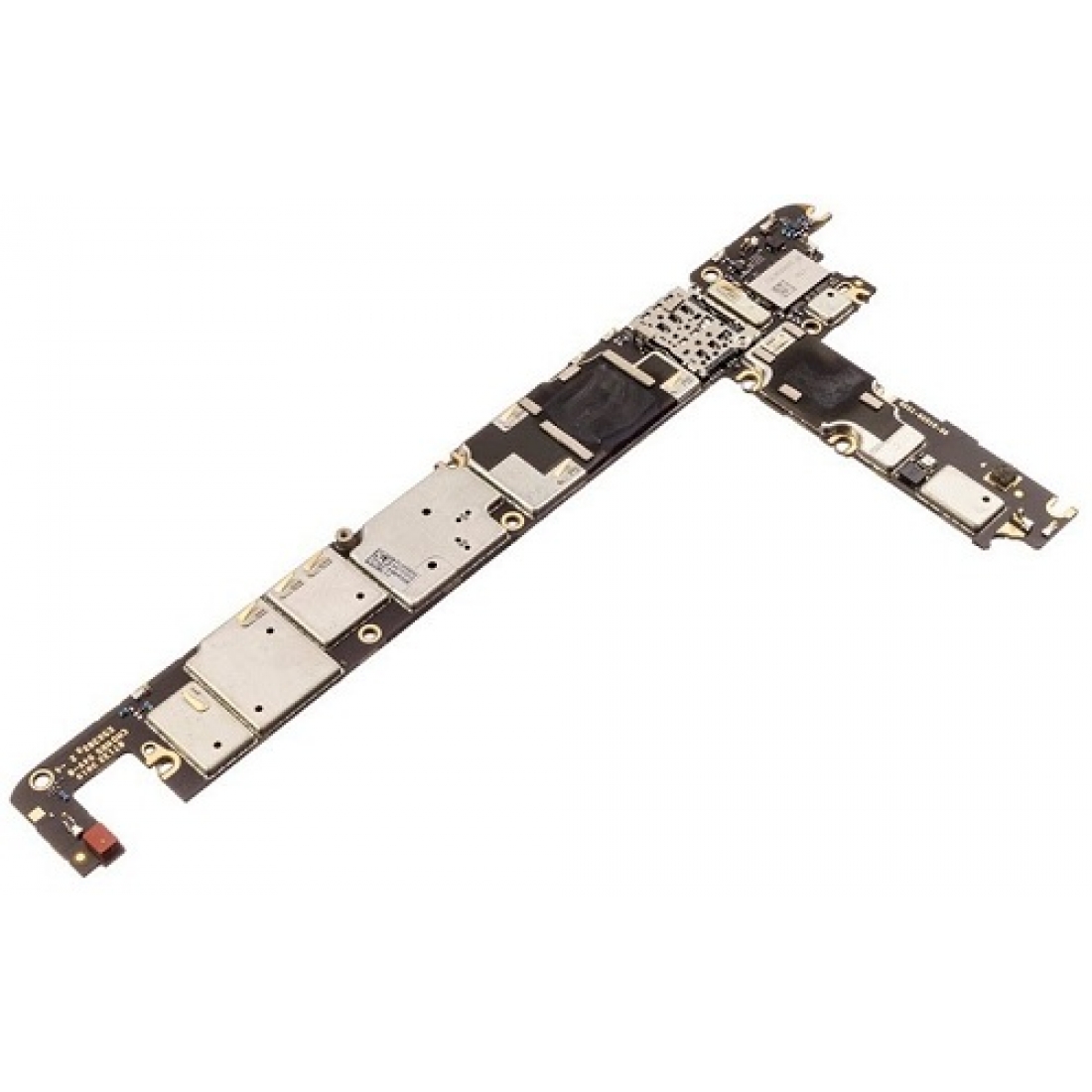
– Alright, time to get this motherboard outta there! Grab your trusty spudger and gently pry the top end of the motherboard up and out of the phone’s frame. It’s like giving it a little high-five, but with a tool! No worries if it takes a couple of tries, just be careful and you’ll be golden.
Tools Used
Step 40
The connectors for the rear-facing camera module take a little detour around the motherboard, and guess what? The camera module isn’t glued down, so it might just pop out along with the motherboard when you get to this step. No worries, just keep an eye on it!
– Gently lift the motherboard out, making sure to avoid any ribbon cable connectors that might want to play hide and seek.
– Carefully take out the motherboard completely.
– When you’re putting the motherboard back in, double-check that no ribbon cable connectors are sneaking underneath.
Step 41
– Time to get up close and personal with your device’s rear-facing camera module! Use a trusty pair of tweezers to carefully remove it. If you need help, you can always schedule a repair
Tools Used


