DIY Google Pixel 7a Vibration Motor Replacement
Duration: 45 minutes
Steps: 53 Steps
Hey there, techie! This step-by-step guide is all about you getting that fix done. We’re here to make sure you’ve got all the info you need to get the job done, but if you’re feeling lost or overwhelmed, you can always schedule a repair.
Get ready to bring your phone’s vibe back to life. If your Pixel 7a has lost its buzz or the vibrations are feeling a little weak, it’s probably time to swap out the vibration motor. Don’t worry, we’ve got you covered. This step-by-step guide will walk you through the process. Note that if you’ve got the Verizon model (G0DZQ), some of the photos might look a bit different, but the steps are the same. Also, keep in mind that if your battery is swollen, you’ll want to take some precautions. You’ll need some replacement adhesive to complete the job. Just a heads up: any repair can affect your phone’s water resistance, so make sure to reapply that adhesive like a pro. If you need help, you can always schedule a repair.
Step 1


– First things first, give your phone a little break. Unplug all those cables and power it down completely. You got this!
Step 2


– Time to get started! Insert a SIM eject tool, or a trusty paper clip, into the SIM card tray hole – it’s like a little key to unlock your phone’s secrets.
– Gently press the SIM eject tool into the hole, and the SIM card tray should pop out – easy peasy!
– Now, carefully remove the SIM card tray. You’re doing great! If you need help, you can always schedule a repair
Step 3

Heat the phone just enough to make it warm to the touch. Too much heat can harm the screen, rear cover, or battery.
Want to loosen up that rear cover? Try using a hair dryer, heat gun, or hot plate to give it a little warmth. This should help make it easier to remove.
– Warm up your trusty iOpener and gently place it on the bottom edge of the rear cover for a cozy three minutes.
Tools Used


Step 4


In the next three steps, we’ll show you how to use the Anti-Clamp, a nifty tool we created to make opening your device a breeze. If you’re not using the Anti-Clamp, jump ahead three steps for an alternative method.
For full instructions on using the Anti-Clamp, check out this guide.
– First, let’s get this repair started! Pull that blue handle backward to unlock the Anti-Clamp’s arms – it’s like releasing a little robot from its sleep.
– Now, carefully slide the arms over the bottom edge of your phone. Make sure one suction cup is on the rear cover and the other is on the screen – this will help you get a good grip.
– Almost there! Squeeze those cups together to create some serious suction. If you need help, you can always schedule a repair
Step 5


– Pull the blue handle forward to keep the arms locked in place. Turn that handle clockwise one full turn – make sure it goes all the way round, and you’ll see the suction cups start to stretch. Keep ’em aligned as they stretch – if they slip, remove the Anti-Clamp and add some tape to help ’em stick.
Step 6

Keep that heat on – if the rear cover starts to cool down while you’re setting up the Anti-Clamp, just give it another blast with the iOpener to keep things loose.
If the adhesive is being stubborn, try twisting the handle a quarter turn clockwise and waiting another minute. If it’s still not cooperating, grab a hair dryer or heat gun to warm things up again.
– Get your phone comfy by placing something under it, so it’s level and cozy between the Anti-Clamp’s arms.
– Now, be patient and wait about a minute – or until you see the adhesive start to separate – for a gap to form along the bottom edge of your phone.
– Time to get a little more hands-on: insert an opening pick into the gap between the rear cover and the frame.
– You’re making progress! Remove the suction cups from your phone using their pull-tabs and set the Anti-Clamp aside for now.
Tools Used
Step 7


Already got an opening pick in with that Anti-Clamp? You rock! Skip this step and get on with the good stuff!
– Grab a suction handle and place it right in the middle of the bottom edge of your rear cover.
– With a strong, steady pull, lift that handle up until you see a little gap appear between the rear cover and the frame.
– Now, take the tip of your opening pick and gently slide it into that gap.
– Time to say goodbye to the suction handle!
Tools Used


Step 9


Keep those opening picks angled up, like you’re trying to slice a pizza! Just keep going until the back cover pops right off.
– Tilt that opening pick upwards, making sure the tip is pointing away from the frame. You’ve got this!
– Gently glide your pick over to the bottom left corner of the rear cover. Just like that!
– Keep that pick right where it is to stop the adhesive from getting too cozy and sealing back up.
Step 10


– Pop in a second opening pick at the bottom left corner, just like placing a bookmark in your favorite novel.
– Gently glide that new pick across to the bottom right corner of the rear cover to break free the sticky bottom edge adhesive.
– Keep that pick snugly in place to stop the adhesive from getting all clingy again.
Step 11

Alternatively, feel free to grab a hair dryer, heat gun, or hot plate to gently warm up that rear cover. Just be sure to keep an eye on the temperature—nobody likes a phone that’s too hot to handle!
– Give that right edge of the rear cover a little love with a heated iOpener for two minutes. Let’s get this party started!
Tools Used
Step 12


Make sure to keep your pick under 5 mm deep on the right edge so you don’t accidentally give the wireless charging coil a little too much excitement.
Want a super clear visual? Just grab your trusty permanent marker and mark your pick 5 mm from the tip! You’ll be a pro in no time!
– Pop a third opening pick into the bottom right corner of that rear cover, just like a pro!
– Gently glide your pick up the right edge of the rear cover to break free that stubborn adhesive. Stop right when you hit the camera bar! You’re doing great.
– Keep that pick right where it is to stop the adhesive from making a comeback. You’ve got this!
Step 13

Or, you can use a hair dryer, heat gun, or hot plate to warm the rear cover. Just be careful not to overheat the phone!
– Heat up your iOpener and give the left edge of that rear cover some love for two minutes. It’ll be worth it, trust us!
Tools Used
Step 14


Be careful not to slide your pick in more than 3 mm along the left edge; we wouldn’t want you to accidentally poke the wireless charging coil or mess up the rear cover foam pad!
Here’s a fun trick: measure 3 mm from the tip of your pick and mark it with a permanent marker for a handy visual guide.
– Pop a fourth opening pick into the bottom left corner of the back cover.
– Slide that pick up along the left edge of the rear cover to pry apart the adhesive. Halt when you hit the camera bar.
– Keep this pick in place to stop the adhesive from resealing.
Step 15

Another option is to gently warm up the rear cover using a hair dryer, heat gun, or hot plate. Just be careful not to make your phone too toasty!
– Get that iOpener nice and toasty and press it against the top edge of the rear cover for a couple minutes. Think of it like a warm hug for your device!
Tools Used
Step 16


You’ll notice a thick strip of adhesive along the antenna housing – don’t worry, it’s easy to work with!
If the pick won’t fit, try starting with the small gap near the camera bar from your previous step. It’s a great place to begin.
– Now it’s time to add a fifth opening pick to the top left corner of the rear cover. Carefully insert it between 8mm and 10mm deep – that’s about halfway between the tip of the pick and the logo. You’re making great progress!
– Next, slide your pick halfway across the top edge. This will help loosen the antenna bracket adhesive. Stop when you reach the halfway point along the top edge. You’re doing fantastic, keep it up!
Step 17


Be careful not to insert your pick more than 3 mm to avoid damaging the antenna housing’s graphite tape. Let’s keep that phone in great shape!
– Gently pull your opening pick out to about 3 mm deep. You’ve got this!
– Now, slide that pick over to the top right corner to cut through the remaining adhesive along the top edge. Easy peasy!
Step 18


Keep those picks pointed up and away from the frame – you’ve got this!
– Now it’s time to get that rear cover off – gently roll the top edge pick so its flat edge slips under the cover.
– Next, work your magic on the picks on either side of the camera bar, rolling them so their flat edges are snug under the bar.
Step 19


Hey there! Be super gentle with that rear cover—no bending allowed! Just pry it a little to loosen the adhesive around the camera bar. If it’s being a bit stubborn, give the rear cover a little wiggle side-to-side to help break that adhesive free.
Beneath the camera bar, there’s a sneaky long strip of adhesive holding that rear cover in place. Let’s get it off together!
– Time to get this repair started! Use those handy opening picks to carefully pry the top edge of the rear cover away from the frame, starting under the camera bar.
– Gently pry back and forth – be patient, it might take a little wiggling – until the camera bar starts to loosen up.
Step 20


– Alright, time to loosen things up! Slide those opening picks from the camera bar down those long edges of the rear cover. This’ll help separate any adhesive that might have gotten a little too cozy.
Step 21


– Let’s get started by removing the rear cover – it’s time to take a peek inside!
– When you’re putting everything back together, remember:
– Now’s the perfect time to turn your phone on and make sure it’s working properly. Give it a quick test, then power it back down before finishing up the reassembly.
– To wrap things up, follow our guide on how to apply new adhesive and get your rear cover back in place. If you need help, you can always schedule a repair.
Step 22


– Warm up your trusty iOpener and give it a cozy minute on the flash unit. This will help melt the adhesive that’s holding it onto the logic board cover, making it easier to do your magic.
Wanna be a pro at warming up that flash just right while making sure your other gizmo friends stay cool and shielded from heat harm? Don’t forget to let your soldering iron do the warm hugging – no need to get all intense, just till it’s nice and warm, like a soft blanket on a snuggly day!👍 Remember, our pals battery and its buddies over there don’t like a hot scene, so keep it chill. If you’re feeling all hot and bothered, or just need some cool advice, don’t sweat! You can always hit us up 📱💻 to get schooled in repair stability.😉 schedule a repair.
Another option is to grab a hair dryer or a heat gun and give that flash a gentle warm-up.
Tools Used
Step 23


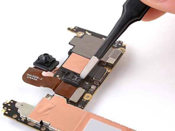
Watch out for that flash cable! It’s super delicate, so handle it with care to keep it safe and sound.
– Alright, let’s get that flash separated! Slide your pick under the right edge of the flash, gently prying it away from the cover. You’re almost there!
Step 24


– If the copper tape lifted away with the flash, you’ve got this! Use tweezers or your nimble fingers to peel off the black foam residue from the logic board cover.
Tools Used

Step 25


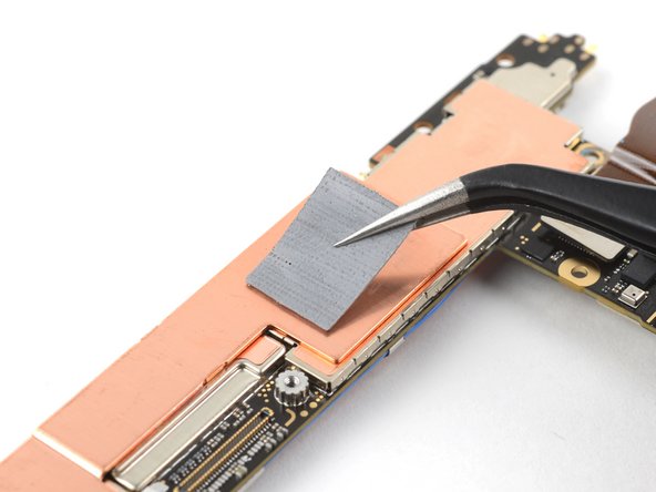
Watch out for that battery! It’s a bit sensitive, so keep your tools clear during this step.
Alright, that copper tape was holding on tight, huh? If it’s still stuck on the logic board cover and you have a new one ready, go ahead and give that old tape the boot!
– Warm up the underside of the flash with a heated iOpener for a minute. It’s like giving the flash a nice little spa treatment!
– Keep the flash cable neck steady and use tweezers to gently peel off the copper tape from the flash unit. It’s like removing a pesky sticker, but way more high-tech!
Step 26


Alright, so this Pixel 7a uses some special screws called Torx Plus. But don’t worry, your standard Torx drivers might still work! Just grab your T2 bit for the 1IP screws and the T3 bit for the 3IP screws. Remember to keep that pressure steady and downward, don’t want to strip those little guys. You got this!
– Get ready to tackle those thirteen 4.3 mm screws holding the logic board cover in place. Grab your trusty 3IP Torx Plus driver and let’s get to work!
– Now, let’s move on to the right edge of that cover. Use your 1IP Torx Plus driver to remove the single 1.5 mm screw—that’s the one securing everything in that area. You’ve got this!
Step 27


– Let’s pop that logic board cover off! Start by gently sliding an opening pick between the bottom right corner of the cover and the frame.
– Now, give that pick a little pry to release the clip holding the cover in place. You got this!
Step 28


– Gently pry up the top edge of the logic board cover and carefully guide the flash unit through its designated cutout – take your time, it’s a bit of a tight squeeze!
– When putting everything back together, make sure to thread the flash unit through its cutout as you lower the logic board into place, and you’ll be golden!
Step 29


– Time to ditch the wireless charging assembly – carefully remove it to move forward with your repair.
Step 30

– Let’s get started! Use your trusty 1IP Torx Plus driver to remove the 1.5mm screw that’s holding the connector cover in place.
– Now it’s time to get a little handy – use tweezers or your fingers to gently remove the cover.
– When you’re putting everything back together, make sure to tuck the upper left corner of the cover under the hook on the logic board before securing it with its screw.
Tools Used
Step 31

Yo, Verizon model (G0DZQ) Pixel 7a comes with a little surprise – an extra cable and connector for the 5G mmWave antenna. Apart from this bit of bling, the rest of the repair steps are the same, regardless of the phone model. Let’s keep it rolling!
Step 32


Alright, let’s get that connector back on track! Start by lining it up over the socket like a pro. Give one side a gentle press until you hear that satisfying click, then do the same on the other side. If it doesn’t pop in right away, don’t sweat it—it might take a few tries to get everything just right. You’ve got this!
– Time to get started! Insert the flat end of a spudger under the top edge of the battery press connector, making sure it’s securely in place.
– Now, gently pry straight up to disconnect the battery press connector – it’s easier than you think!
Tools Used

Step 33

– Grab your 3IP Torx Plus driver and pop out that 4.3 mm screw holding the earpiece speaker in place. Easy peasy!
Step 34


– Gently nudge the bottom edge of the earpiece speaker upwards.
– Now, pull that speaker down towards the bottom of your phone, and let the red gasket pop free from its cozy little cutout in the frame.
– Time to say goodbye to the speaker—remove it with care!
Step 35

– Grab your trusty 3IP Torx Plus driver and take out those two 4.3 mm screws holding the antenna housing to the frame. It’s super easy, just like unscrewing a pickle jar!
– When it’s time to put everything back together, give that housing a gentle press down while you snug up those screws. Teamwork makes the dream work!
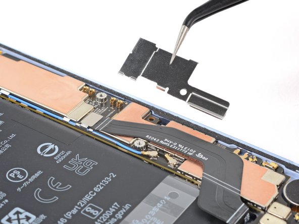
Step 36


– Oh, snap! It’s time to show your phone’s antenna housing some love. Carefully slide in a trusty opening pick at the top left corner, and gently pry up to release those pesky clips keeping the housing in place.
– Once you’ve got the housing Good Samaritan’d, hold that graphite film like it’s your best friend during reassembly. (Don’t worry, it’s just keeping a low profile!).
Step 37


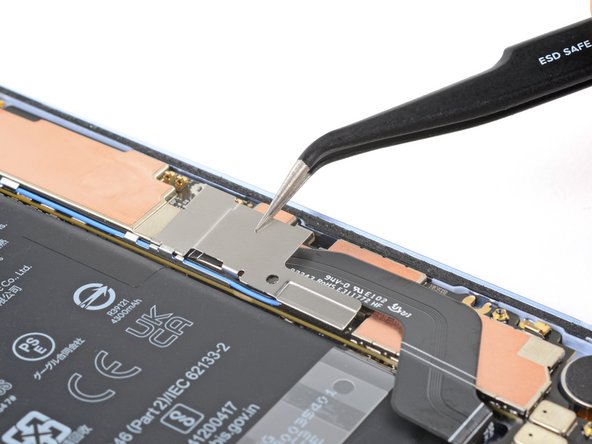
– Give that antenna housing a little lift by the bottom leg and then gently pull the top edge out from the frame.
– Now, just remove the housing. You’ve got this!


Step 39

As an alternative, grab a hair dryer or heat gun to gently warm up that sticky adhesive. Just heat the tape until it’s cozy and warm, not scorching hot!
– Give that front-facing camera a warm hug with a heated iOpener for about a minute! This will help loosen up that pesky copper tape adhesive, making your repair a breeze.
Tools Used
Step 40


Those camera lenses are delicate little things, so be gentle with them! They’re like the eyes of your device, and you wouldn’t want to hurt their feelings, right?
If the tape seems stubborn, don’t fret! Grab a handy tool like angled tweezers and gently pry up the edge of the tape. Once you have a little space, slide a pick underneath to help lift it up.
– Gently slide the tip of your opening pick beneath that shiny copper tape by the front-facing camera.
– Take your time and carefully lift the tape away from the logic board.
Tools Used
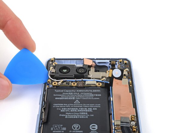
Step 41


Handle your tools with care, and keep them away from the front-facing camera lens—it’s not a fan of unexpected hugs!
– Gently slide the tip of your opening pick between the right edge of the front-facing camera cable and the frame. We’re just easing it in, nothing too forceful!
– Now, carefully glide your pick underneath that cable to help it break free from the adhesive holding it in place. It’s all about that smooth separation!
Tools Used
Step 42
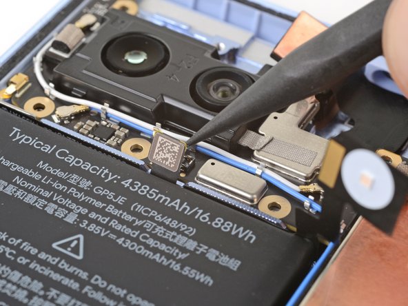

Handle with care – avoid touching the rear camera lenses to keep them smudge-free and functioning properly.
This little connector is a busy bee, hooking up the power button, volume buttons, flash unit, and upper microphone. It’s got a lot going on!
– Gently use the tip of a spudger or your trusty fingernail to lift and disconnect the press connector located just above the battery. You’re doing great!
Tools Used
Step 43

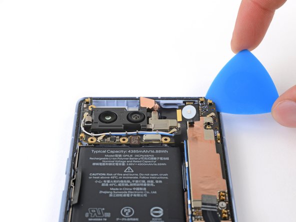
– Slide your trusty opening pick into the top right corner where the logic board meets the frame.
– Gently lift to release the logic board from its snug little home.
– Now, wiggle your pick into the gap by the white antenna cable and pry up the top left corner of the logic board.
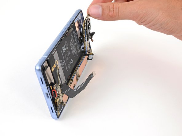
Step 44


Handle the logic board with care, it’s a bit on the fragile side! Gently ease the lower edge away from the frame without bending it.
Hold your horses! Don’t pull the logic board out just yet—it’s still buddies with the frame via the screen cable.
Keep those delicate flash, front-facing camera, and press connector parts happy by making sure they don’t get trapped under the frame. Smooth sailing, right? 😉
– Time to free that logic board! Gently lift the top edge of the logic board from the frame.
– Now, slide that logic board to the right, like you’re opening a door. Make sure the cutouts on the board clear those bumps on the frame.
– Keep pulling, and that charging port will come right out of its little home in the frame.
– When you put it all back together, just slide that logic board down towards the bottom and push the charging port in until it’s snug. You got this!
Step 45

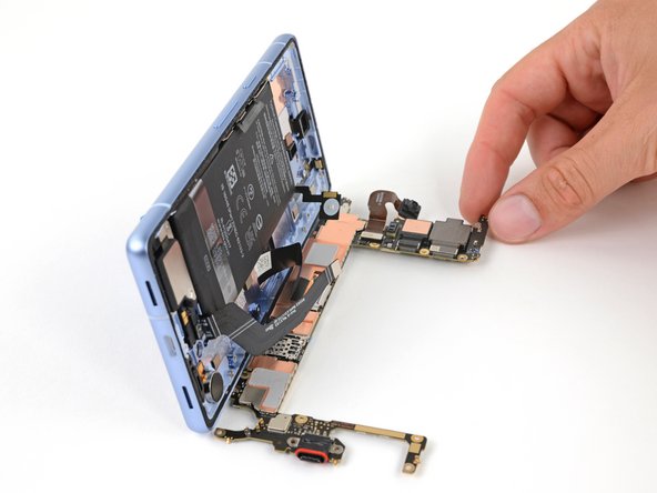
Hey there! Just a friendly reminder – the logic board can get a little wobbly during this step. Keep it steady, but be sure to avoid grabbing it by the camera lenses or connectors, okay?
Also, watch those thermal pads on the underside of the logic board. They’re delicate, so try not to give them any unnecessary attention.
No suction handle? No problem! Just lean your phone against something sturdy, like a hefty box or a thick book.
– Grab your trusty suction handle and stick it to the left side of the screen, making sure the handle is facing down like it’s ready for action.
– Now, let’s get that phone standing tall! Prop it up so it can show off its best side.
– Gently tilt the logic board down and lay it flat like a comfy pancake. If you see any cables in the way, just give them a little nudge to clear the path.
Tools Used
Step 46


– Alright, let’s loosen up that screen connector cover! Use your 3IP Torx Plus driver to remove the 2 mm screw holding it down.
– Time to take that cover off! No sweat, it’s just a quick pop.
– When you’re putting everything back together, make sure you hook the bottom edge of the cover into its slot on the logic board before tightening that screw. You’ll be a pro in no time!


Step 49

Keep those fingers and tools away from the sensor! It’s sensitive, and a little touch can mess things up.
– Alright, let’s check out that front sensor rubber gasket. If it’s still hanging out on the frame or got a little out of whack, just give it a gentle nudge and set it aside.
– When you’re putting everything back together, make sure that gasket is snug on the front sensor on the logic board. You want the little cutout to be pointing towards the top. You got this!
Step 50

– During reassembly, it’s time to make sure your device is cool under pressure! If you’re giving that logic board a second chance, check out the thermal pad. If it’s looking a little worse for wear, give it a clean sweep and apply a fresh pad. Now, if you’re using a brand new logic board and it’s thermal pad-less, take a moment to give it a warm welcome with a brand new one.
Step 51

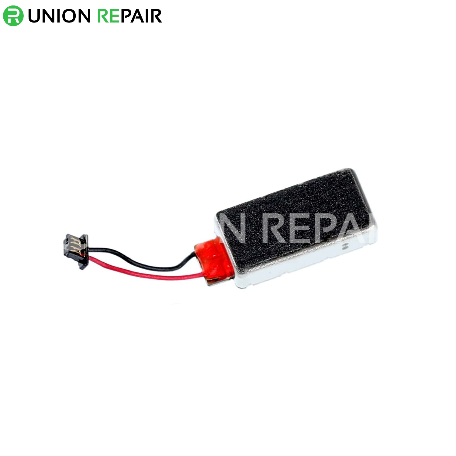
If you’re feeling a bit adventurous, warm up the vibration motor gently with a hair dryer or heat gun. Just remember, keep it moving—don’t linger in one spot for too long, as the battery and its buddies are a bit picky about too much heat!
– Get that vibration motor nice and toasty! Apply a heated iOpener for two minutes.
Tools Used
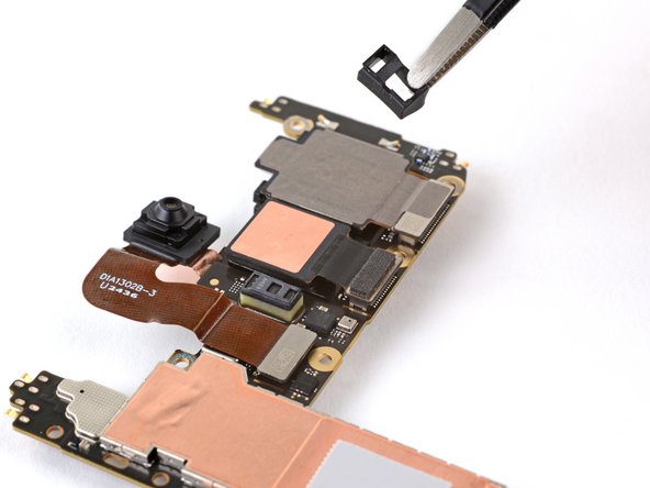
Step 52
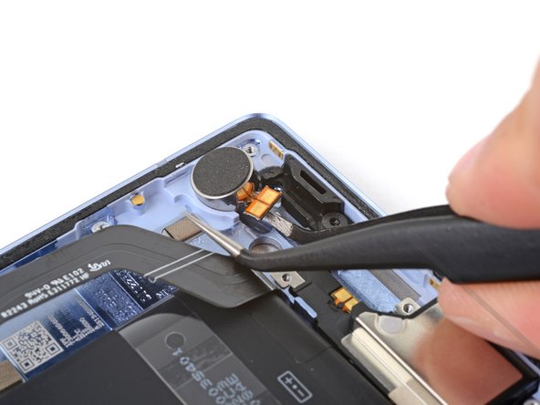

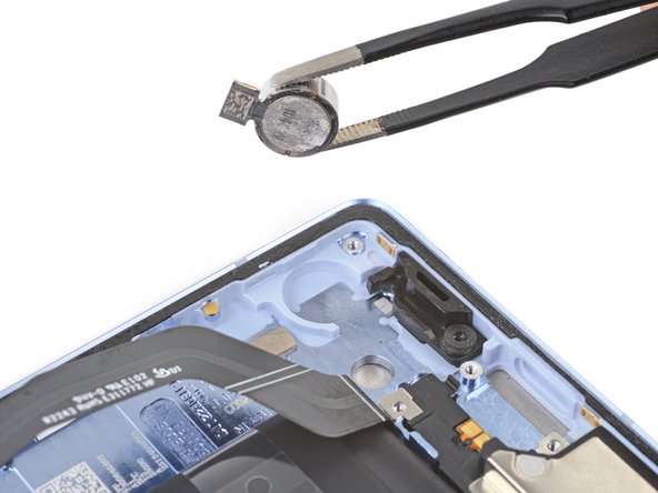
Hey, before you start prying, make sure that arm is snuggly under the vibration motor body. If you pry on just the contact pads, you might break ’em. And we wouldn’t want that, would we? 😉
– Carefully slide one side of your angled tweezers in between the vibration motor contact pads and the frame. It’s like giving your device a gentle nudge!
– Keep sliding that tweezers arm further under the pads until it snuggles right under the vibration motor’s body. You’re doing great!
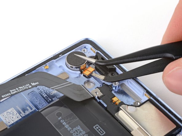
– Now, give that tweezers arm a little twist to break free the vibration motor adhesive. You’re almost there!
Tools Used
Step 53

If your vibration motor doesn’t have adhesive pre-installed, no worries! Just add some thin double-sided tape like Tesa Tape to the motor before you press it into place. You got this!
– Now you’re ready to put your device back together, just reverse the steps!
– Want to run a quick check to make sure everything’s working as it should? Click here to run the Pixel Diagnostic tool.
– When it’s time to retire your device, make sure you recycle it properly with an R2 or e-Stewards certified recycler.
– Didn’t quite go as planned? No worries! Take a look at our basic troubleshooting tips, or ask our Answers community for some extra help.
– Didn’t finish the guide? No problem, just click ‘Cancel’.
–
Success!