DIY Google Pixel 9 Pro XL Rear Cameras Replacement – Step-by-Step Guide
Duration: 45 minutes
Steps: 43 Steps
Hey there! This repair guide is brought to you by the awesome team at Salvation Repair. It’s packed with helpful tips and tricks to get your device back in tip-top shape. If you find yourself needing a little extra help, feel free to schedule a repair with us! We’re always here to lend a hand.
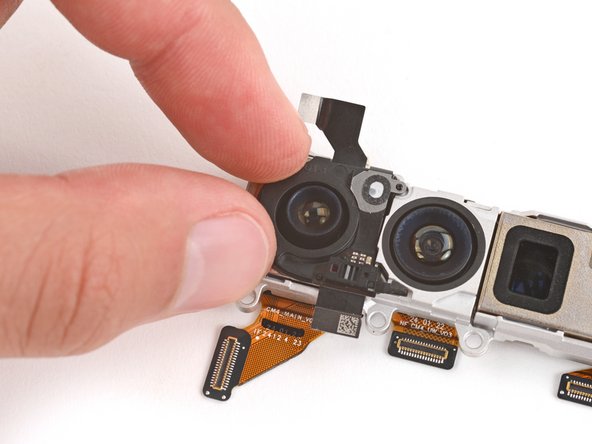
Get ready to dive into some camera magic! This guide will walk you through the process of swapping out the rear cameras (wide, ultrawide, and telephoto) for your Pixel 9 Pro XL. The new cameras come in a handy housing, and guess what? You’ll need to replace all three at once—so if one is acting up, it’s a team effort! If your photos are looking a bit wobbly or you’re not capturing any snapshots at all, it’s time to give those cameras a fresh start. Don’t forget, you’ll also need some replacement autofocus sensor and rear cover adhesives to wrap things up nicely. Just a little heads up: any repair might impact your phone’s water resistance, so make sure to reapply that rear cover adhesive carefully if you want to keep those splashes at bay. If you need help, you can always schedule a repair.
Step 2
When peeling back the adhesive, be careful not to poke your tool more than 3 mm under the rear cover—let’s keep those internal components safe and sound!
Grab your opening pick and measure out a cool 3 mm from the tip. Give it a little mark with a permanent marker so you know where to stop. If you’re feeling crafty, you can stick a coin onto the pick at the same 3 mm mark instead!
Step 3
– Grab a suction handle and stick it right on the bottom edge of the rear cover, keeping it nice and close to the edge. Let’s get that cover off with style!
Tools Used
Step 4
– Give that suction handle a confident tug! We’re looking to create a tiny little wiggle under the rear cover.
– Slide the sharp tip of your opening pick into that newfound gap. You’re doing great!
Tools Used
Step 5
Hey there! Just a friendly reminder: be sure not to go deeper than 3 mm with that opening pick.
– Gently glide your opening tool along the bottom edge to break free the adhesive that’s holding it tight.
Step 6
– Gently slide your trusty opening pick along the left edge and up over the top edge to break that adhesive seal like a pro!
Step 7
– Gently glide your pick down the right edge to break free the last bits of adhesive. You’ve got this!
Step 8
Hold your horses! You don’t want to completely take off that rear cover just yet—there’s a sneaky ribbon cable on the right edge keeping it connected to the phone.
Having a bit of a sticky situation? Check the edges for any leftover adhesive and give your opening pick a go to help separate things out.
– Grab that trusty suction handle and gently lift the left edge of the rear cover—swing it over to the right like you’re opening up a well-loved book!
– Now, prop up the rear cover with the suction handle, giving you a clear view of the ribbon cable lurking near the top right corner.
Tools Used
Step 9
– Grab your trusty Torx Plus 3IP screwdriver and gently unscrew those two 5.2 mm-long screws holding down the cable cover. You’re doing great!
Step 10
– Grab your trusty tweezers or just use your fingers to gently pop off that cable cover. You’ve got this!
Step 12
– Let’s kick things off by gently popping off the rear cover. No need to be shy—just give it a little nudge!
– When you’re putting everything back together, remember to use this guide to add fresh adhesive and snugly secure that back cover. You’ve got this!
Step 13
Feel free to take off the tape completely if you’d like, but remember to hang onto it for when you’re putting everything back together.
– Grab the tip of a spudger and use your fingers to gently lift the piece of tape along the left edge of your phone. Just peel it back enough to reveal the bracket and screws hiding underneath – you’ve got this!
Tools Used
Step 14
– Grab your trusty Torx Plus 3IP screwdriver and tackle those two 5.2 mm-long screws holding down the wireless charging cable cover. You’ve got this!
Step 15
– Grab those trusty tweezers or your fingers and gently lift off the cover. You’ve got this!
Step 16
– Gently slide the tip of your trusty opening pick under the wireless charging press-connector and lift it up to disconnect it. You’ve got this!
Step 18
– Get ready for some fun times, dudes! Now it’s time to pop open those tricky screws with the Torx Plus 3 IP screwdriver. Identify those two 2.2 mm-long lads that are holding the wireless charging squad in place. Once you’ve got ’em unscrewed, it’s time to party with your tech! If you run into any sweat during this wild ride, you can always schedule a repair, so you don’t miss out on the awesomeness!
Step 19
– Take out that wireless charging assembly.
Step 21
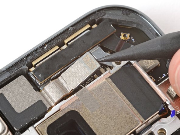
– Grab your trusty Torx Plus 3IP screwdriver and gently unscrew that 5.2 mm-long screw holding the mmWave antenna cover in place. You’ve got this!
Step 22
A snug metal clip keeps the bottom left corner of the mmWave antenna cover nice and secure.
– Alrighty, let’s open up a can of repair whupass! Grab your trusty spudger and stick it under that tab like a tongue on a zipper. Then, be our guest and slide that cover to the right – just like a window sash at your grandma’s house. And voila! You’ve unclipped it like a boss. For more DIY action, you know the drill – schedule a repair!
Tools Used
Step 23
– Gently tug at the right edge of the cover and slide it down to free it from the phone. Easy peasy!
– When putting everything back together, make sure to tuck those two tabs on the top corners into their cozy little recesses in the frame, then give the cover a firm push down to snap it back into place. You’ve got this!
Step 24
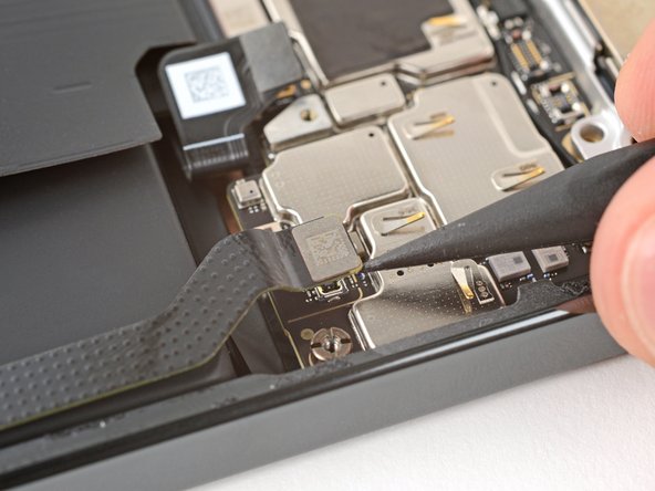
– Grab your trusty spudger and gently lift up to disconnect the mmWave antenna press connector nestled in the top right corner of the logic board. You’ve got this!
Tools Used
Step 26
Hey, keep those camera lenses safe! If you accidentally bump them, just give them a quick wipe with a clean microfiber cloth. No worries!
– Get your paws ready for some tech TLC! Carefully move that front-facing camera cable out of the way so you can get to the mmWave antenna screw. Now, grab your awesomely cool Torx Plus 3IP screwdriver and loosen that 4.2 mm-scrumptious screw holding the mmWave antenna in place. Woohoo, you’re making great progress!
Step 27
– Hey there! Super cool, you’re now ready to roll up your sleeves and tackle this mmWave antenna replacement. Time to switch into repair mode – here’s what you gotta do: Use a pair of tweezers (or your bare hands if ya dare) to remove that fancy mmWave antenna. Once you’re done with that, make sure when you’re reassembling – that’s the fun part – to put the antenna in under the front-facing camera cable. Almost there! If you run into any roadblocks or feel like you need a lil’ extra help, remember, you can always schedule a repair with our pro squad!
Step 28
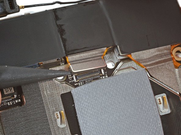
– Grab a spudger and gently nudge it under those three stubborn press connectors at the bottom of the logic board. You’ve got two bigger ones hanging out near the center and a smaller one chillin’ in the bottom right corner. Give them a little love and disconnect them!
Tools Used
Step 29
– Grab your trusty Torx Plus 3IP screwdriver and let’s get this party started! Carefully unscrew those two 5.2 mm-long screws that are holding down the metal cover in the top left corner. You’ve got this!
Step 32
– Gently slide one arm of your angled tweezers under the metal neck of the antenna connector and lift it straight up to disconnect. Easy peasy!
– When you’re putting it back together, use your tweezers to hold the connector nicely over its socket. Then give it a gentle press down with your finger or a spudger—the connector should pop into place with a satisfying little ‘snap’. If it’s not cooperating, just reposition the head and try again. You’ve got this!
Tools Used
Step 33
If you’re missing a standoff screwdriver, don’t panic! You can totally use a flathead screwdriver that’s as wide as, or even a bit bigger than your screw. To avoid any mishaps, make sure your screwdriver is snugly aligned with your screw and keep some steady pressure going. Check, check, and you’re good to go!
– Alright, let’s get this party started! Use your trusty standoff screwdriver to remove the 4.8 mm-long standoff screw from the bottom right corner of the logic board. It’s just hanging out there, waiting to be freed.
Step 34
– Grab your trusty spudger and gently nudge the top edge of the logic board until you can give it a good grip with your fingers.
– Once you’ve got a hold of the right side of the logic board, carefully pull it out, keeping an eye out for any cables that might want to be friends with it (one front-facing camera cable and four cables along the bottom edge).
– When it’s time to bring everything back together, make sure to hold the front-facing camera cable out of the way and lower the logic board into its cozy home, ensuring the four cables along the bottom edge don’t decide to sneak under.
Tools Used
Step 35
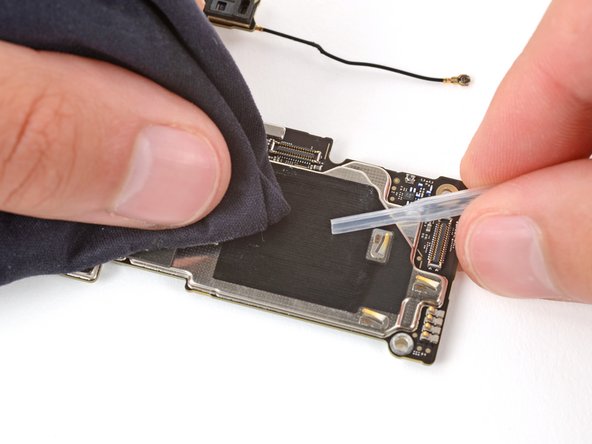
– Alright, time to put everything back together! But first, let’s check out that logic board thermal pad – it’s either chillin’ on the bottom of the logic board or hangin’ out on the frame.
– If that pad’s lookin’ good, you can skip ahead to the next step. But if it’s lookin’ a little rough, grab the flat end of your spudger and gently scrape it up to remove it.
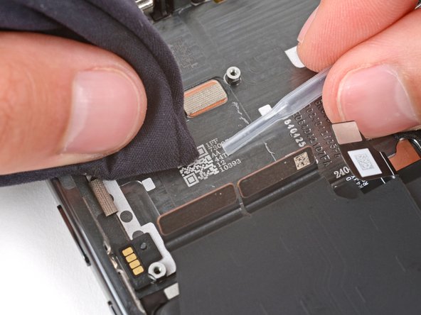
– Now, get some isopropyl alcohol (make sure it’s 90% or higher!) and a microfiber cloth and wipe away any thermal pad residue from the frame and the bottom of the logic board. Get it nice and clean!
– Finally, stick that new thermal pad back where it belongs on the frame. We’re almost there!
Tools Used
Step 36
Heads up: When you disconnect the cameras in the next two steps, make sure you don’t accidentally knock off any of the small, surface‑mounted components!
– Lift the logic board just above your workspace while gently disconnecting the rear cameras—remember, no pressing down on the board, or you might accidentally harm those delicate components!
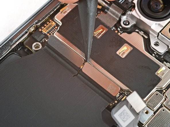
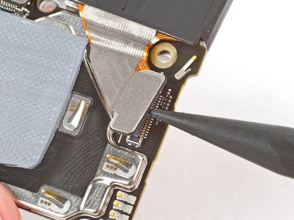
– Grab your trusty spudger and use its tip to carefully pry up and disconnect the autofocus sensor press connector located at the top of the logic board, close to the left edge.
Tools Used
Step 37
– Gently turn the logic board over so that the underside is facing up—it’s like giving it a little flip!
– Grab your trusty spudger and use its pointy end to carefully lift and disconnect the three camera press connectors. You’ve got this!
Tools Used
Step 38
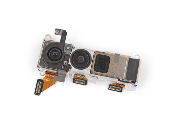
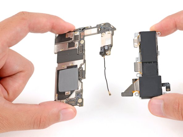
– Grab the logic board with one hand while using your other hand to carefully detach the rear cameras. Easy peasy!
– When you’re putting everything back together, just remember: the three camera cables like to hang out on the bottom side of the logic board, while the autofocus sensor cable prefers to chill on top. Keep it organized!
Step 39
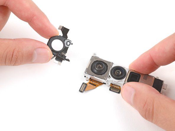
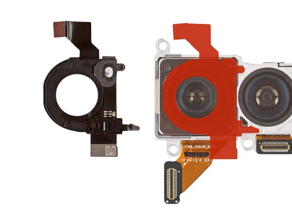
First things first, take a peek at your shiny new replacement rear cameras! Do they come with an autofocus sensor? If not, no worries! Just follow the next steps to carefully remove and transfer the sensor from your trusty old cameras.
If you find yourself in a bit of a pickle, you can gently warm the sensor with a hair dryer — just remember, too much heat can make the plastic go all wonky!
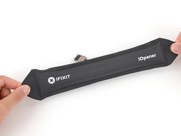
– Warm up your iOpener and gently press it against the top of the rear cameras to loosen up that pesky adhesive holding the autofocus sensor in place. You’re getting closer to a successful repair!
Tools Used
Step 41
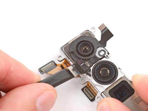
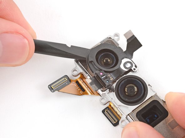
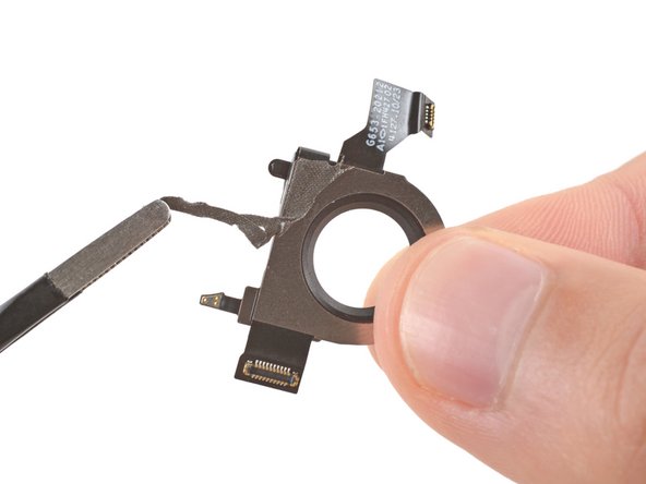
– Gently wiggle the autofocus sensor free with your fingers—no tools needed!
– Grab some tweezers and carefully peel off any sticky residue from the sensor’s underside.
Step 42
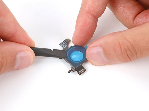
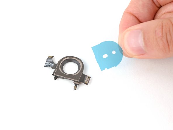
– Alright, let’s get this party started! Peel off the big, clear plastic liner from your replacement autofocus sensor adhesive.
– Now, get your adhesive all nice and cozy on the bottom of your sensor. Use a spudger to press it down good and tight. You got this!
– Time to get rid of the rest of that blue liner, We’re almost there!
Tools Used
Step 43
Remember, you’re the superstar of this repair, and no camera glasses will judge you if you accidentally touch ’em. Wipe ’em down with a lint-free superhero cape and you’re golden!
On the left side of the middle camera, you’ll spot some cutouts that perfectly align with the small bumps on the right side of the sensor. It’s like they were made for each other!
– When it’s time to put your gadget back together, just work your way back through the steps like a pro!
– Feeling curious? Run a diagnostics test using the built-in Pixel Diagnostic tool by clicking right here.
– Got some e-waste? Make sure to take it to an R2 or e-Stewards certified recycler; it’s the responsible thing to do!
– If things didn’t go smoothly, don’t stress! Give some basic troubleshooting a shot, or seek advice from our helpful community.
– If this guide didn’t quite hit the mark for you, no worries, you can always choose to cancel.
–
Success!


