DIY Google Pixel XL Fingerprint Sensor Replacement Guide
Duration: 45 minutes
Steps: 32 Steps
This repair guide comes straight from the talented folks at Salvation Repair, and while it’s not officially backed by Google, we think you’ll find it super helpful!
Just a heads up: the Pixel XL’s display panel is a bit of a delicate flower, so handle it with care!
Hey there! Ready to get your hands dirty? This step-by-step guide will walk you through swapping out the fingerprint scanner on your Google Pixel XL. No worries, it’s only secured with some light adhesive. But heads up—the Pixel XL’s display is pretty delicate and sticks to the frame like glue. So, careful when you’re prying it off. There’s a good chance you might crack the display, especially if it’s already got some tiny fractures. Remember to apply lots of heat and take it slow during the prying stage. If you need help, you can always schedule a repair.
Step 1


– Take a SIM eject tool, SIM eject bit, or even a trusty paperclip, and poke it into the small hole on the left side of your phone, near the top.
– Give it a press to pop out the tray.
Step 2


Feeling a bit hot under the collar? If you’ve got a hair dryer, heat gun, or hot plate handy, they can help you out! Just remember to keep a close eye on the heat – we wouldn’t want to send your display or internal battery on a one-way trip to heat damage land!
– Warm up an iOpener and place it on the top edge of the display for a couple of minutes.
– Before you start prying, be aware of these spots:
– Thin adhesive lining the display panel
– Thick adhesive areas
– The OLED display panel—super easy to damage
– The display cable, which can get damaged while prying
Tools Used

Step 3


Keep that pick within 13 mm (0.5 inches)! Going beyond that could cause some trouble for your display assembly. Stay safe and happy repairing!
Feel free to grab a playing card instead of an opening pick to help you get started with that first entry.
– When the edge is warm to the touch, pop a suction cup close to the edge.
– Lift the suction cup and slide an opening pick into the gap.
– If creating a gap is tricky, give the edge another warm-up and try again.
Step 4


Hey there! Just a friendly reminder: keep your cutting depth to a maximum of 13 mm (0.5 inches). Going deeper might lead to display drama!
Also, there’s a nifty mesh covering the earpiece speaker at the top of the screen. If you don’t have a replacement mesh handy, be extra careful not to damage or misplace it. We know you got this!
– Gently glide the opening clip along the top edge to cut through that sticky adhesive like a pro.
– Pop an opening pick in the gap to keep that adhesive from making a comeback.
Step 5


Make sure not to slide the pick more than 1 mm (1/32″) along the edge, or you might mess up the display assembly. If you need help, you can always schedule a repair
– Warm up that iOpener and place it on the right edge of your phone for about two minutes. Let’s get it cozy!
– Slide an opening pick in near the top edge of the phone, right where you’ve already made that adhesive slice. You’re doing great!
– Gently maneuver the pick around the right corner. Take your time; it’s all about finesse!
– Carefully glide the pick down the right edge of the phone to slice through the adhesive. Smooth moves!
– Now, let’s do the same for the left edge of the phone. You’ve got this!
Tools Used
Step 6


Keep it cool and don’t slice any deeper than 8.5 mm (1/3″) to avoid wrecking the display cable. If you need help, you can always schedule a repair.
– Warm up the bottom edge with an iOpener for a cozy two minutes.
– Slide a pick in near the right edge where you’ve already loosened that sticky adhesive.
– Gently guide the pick around the corner like a pro.
– Glide the pick along the bottom edge to slice through that adhesive like butter.
Tools Used
Step 7

Hey there! Just a friendly reminder: don’t try to take off the display assembly just yet. It’s still connected by a flex cable, and we wouldn’t want any mishaps!
– Now that you’ve made your way around the phone’s perimeter, gently pry the display assembly up a bit from the right corners – you’re making great progress!
– Use an opening pick to carefully cut through any remaining adhesive, and you’ll be one step closer to a successful repair. If you need help, you can always schedule a repair
Step 8


Watch out for that flex cable! Give it some love and don’t stretch it too much while you’re swinging the assembly around.


Step 10


To reconnect press connectors like this one, line it up and push down on one side until you hear a click, then do the same on the other side. Avoid pressing in the middle to prevent bending the pins, which could cause irreversible damage. If you need help, you can always schedule a repair.
– Grab your trusty spudger and gently nudge up the display cable to disconnect it from its connector. You’ve got this!
Tools Used

Step 11


– Pop off the display assembly.
– For a complete guide on reinstalling your Pixel XL display, check out this link.
– If your new display doesn’t have a speaker grille, just grab some tweezers, gently peel the sticky grille from your old display, and stick it onto the new one.
– Before you put on a new display, clear off any old adhesive from the frame. Use a spudger or an opening tool to scrape it off and high-concentration isopropyl alcohol to clean up any leftover gunk.
– If you’re reusing the same display assembly, make sure to clean off all adhesive residue from both the panel and frame before sticking on new adhesive.
– Turn on your phone and give your repair a test run before applying new adhesive and sealing up the phone.
– When you boot up after reassembly, the screen will go through a calibration sequence. Don’t touch it during this process, or you might mess up the touch calibration and create issues.
Tools Used
Step 12

– Let’s get into it! Start by unscrewing the screws holding the midframe to the back. You’ll want to locate:
– Seven stylishly black 4 mm T5 screws
– Two sleek silver 3 mm T5 screws
Step 13

– The midframe is snugly secured by plastic clips that fit into the edges of the back case, keeping everything in place like a pro! If you need help, you can always schedule a repair.
Step 14


– Locate the tiny notch in the bottom left of the frame and pop in an opening pick.
– Glide the pick along the phone’s bottom edge towards the bottom right corner and park it there.
Step 15


Sometimes things are a bit snug and need a little extra oomph! If it’s feeling tricky, grab a playing card, and gently slide it in for an assist.
– Grab your trusty opening pick and slide it into the right edge of the phone, just a smidge from the bottom.
– Gently nudge the pick upwards along the seam until you hear that satisfying pop of the first clip freeing up.
– Now that you’ve successfully released the clip, keep that pick in place to stop the midframe from sealing back up.
Step 16


No need to go too deep—just 2 mm with the pick will do. Any further might mess with those flex cables.
By now, the right edge of the midframe should be free. If it’s still stuck, just glide an opening clip up and down along the right edge. If you need help, you can always schedule a repair.
– Gently slide an opening pick into the right edge of your phone and move it up towards that sneaky top right clip.
– Carefully glide the pick past the clip to release it from the frame, like a pro!
Step 17


– Grab the midframe’s right edge at the corners and gently lift it up.
– When the left edge feels loose, stop lifting and raise the midframe.
– Take out the midframe.
– To put the midframe back, line it up with the case, then press around the edges until all the clips snap back in place. When done right, the midframe should lie flat.
Step 18


– Grab that trusty spudger and gently lift the battery connector up, disconnecting it with ease!
– Give the battery flex cable a little bend, just enough to keep it from accidentally touching the motherboard. Safety first!
Tools Used
Step 19


If the metal clip from the button strip happens to take a little vacation during your repair, just give it a gentle nudge back into its groove and keep going!
– Grab your trusty spudger, wedge it under the button strip connector, and pop that sucker up. If you need help, you can always schedule a repair.
Tools Used
Step 20

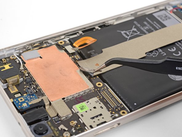
– Grab those tweezers and gently lift the tape at the top of the interconnect cable. If you need help, you can always schedule a repair.
Step 21


– Gently use the tip of a spudger to lift and disconnect the interconnect cable from the motherboard. Remember, you’re doing great!
Tools Used
Step 22


– Gently use the pointy end of a spudger to unplug the black antenna cable from the motherboard, right by the front-facing camera module.
– Carefully guide the antenna cable out of its little retaining clip.
Tools Used
Step 23


– Grab that spudger and gently pop off the white antenna cable from the motherboard near the rear-facing camera module.
– Carefully guide the antenna cable out of its clip. If you need help, you can always schedule a repair.
Tools Used
Step 24

– Pop out those two 3 mm T5 screws holding the motherboard to the frame.
– When you’re putting everything back together, make sure the camera modules and headphone jack module are snug in their spots before securing the motherboard. If you need help, you can always schedule a repair
Step 25


– Grab your spudger and gently pry up the front-facing camera module from its socket. Easy peasy! And remember, if you need help, you can always schedule a repair.
Tools Used
Step 26


– Gently slide the tip of a spudger into the headphone jack port and give it a little upward nudge to help free the port from its cozy socket.
Tools Used
Step 27


Hold your horses! The motherboard is still hanging on by a flex cable, so let’s not try to yank it out just yet.
Don’t forget to pop out the SIM card tray before diving into this step!
– Take the flat end of a spudger, and gently lift the bottom edge of the motherboard – you’re just coaxing it out of its little house.
Tools Used
Step 28


– First things first, find that sneaky fingerprint sensor cable hiding out on the underside of the motherboard, right near the bottom edge.
– Now, grab your trusty spudger and gently pry that fingerprint sensor cable free from its cozy socket.
– Once it’s loose, carefully peel the cable away from the motherboard like you’re unwrapping a present!
Tools Used
Step 29


Having a bit of a struggle? No worries! Just follow this guide to gently pop the fingerprint sensor out of its cozy spot before securing it back to the motherboard. You’ve got this! And remember, if you need help, you can always schedule a repair.
– Gently grab the motherboard by its corners and wiggle it free from its snug little home, but watch out for those pesky cables!
– When you’re putting things back together, make sure those antenna cables slide neatly under the motherboard edges and through the cable notches. They’ve got a path to follow!
– Reconnecting the fingerprint sensor connector might test your patience, but don’t worry, you’ve got this!
– Give that fingerprint sensor cable a little bend so it curves upward near the connector. Just a gentle nudge!
– Now, stand the motherboard up and align it so that the connector fits snugly against the socket. You’re almost there!
– With a steady hand, use your finger to line up the connector and gently press it into the socket. No need to muscle it—just let the socket do its thing and hold it securely!
Step 30


– Place your thumb on the fingerprint sensor and give it a confident push until it pops out of its spot.
Step 31


– Let’s get started by gently removing the fingerprint sensor. No biggie!
– When you’re ready to put the fingerprint sensor back, it’s super helpful to attach it to the motherboard first before sliding it into its cozy spot.
– Make sure to line up the fingerprint sensor’s connector with the motherboard socket, which you can find chilling on the underside near the battery edge.
– Now, with a light touch, press the connector into the socket. Remember, no need to go all Hulk on it! If you do it right, you’ll hear a satisfying click.
Step 32


– Slide the motherboard into place near its spot.
– Use your finger to pop the fingerprint sensor into its groove.
– Make sure the sensor is lined up correctly in the groove.
– Keep going with the reassembly.