DIY Guide: Google Pixel 7a Front Facing Camera Replacement
Duration: 45 minutes
Steps: 52 Steps
Heads up! This repair guide was crafted with love by the pros at Salvation Repair. Learn more about our awesome repair guides here.
Welcome to your repair adventure! This guide will help you tackle the removal or replacement of the front-facing selfie camera on your Pixel 7a. Just a heads-up: if you’re rocking the Verizon model (G0DZQ), it comes with a 5G mmWave antenna, so some images may vary, but don’t worry—the steps remain the same! If your battery looks like it’s been to the gym a little too much and is swollen, take the necessary precautions. You’ll want some replacement adhesive handy to wrap things up nicely. Remember, any repair might affect your phone’s water resistance, so make sure to reapply that adhesive well to keep the water at bay. If you need help, you can always schedule a repair.
Step 1


– Hey there, tech enthusiast! Unplug your device from any cables and make sure it’s fully powered down. This will help us tackle that repair with a clear head and a clickety-clack of excitement!
Let’s have a little fun and boost that lithium-ion battery power! Fully unplug and let your device drain to 25% maximum. Just think, the lower your battery goes, the more fun the refill, am I right? Ah, lithium-ion can be a real character at those high voltage levels. Remember, safety first! If all else fails, you can always tap into our team of battery whiz-kids by heading over to schedule a repair.
Step 2


– Alrighty, let’s shake things up and get your SIM card out! First, find your trusty SIM eject tool, a bit, or a bent paper clip. Insert it into the SIM card tray hole and give it a little press. The tray should pop right out. Now, take that bad boy out and let’s get back to being connected!
Step 3

Just give it a little warmth, like a cozy hug! Don’t go overboard with the heat, though. You wouldn’t want to give your phone a sunburn, would you? Keep it at a comfortable temperature—just hot to the touch. Too much heat can make things a little toasty for the screen, rear cover, or battery.
Alternatively, grab a hair dryer, heat gun, or hot plate to give that rear cover a cozy warm-up.
– Let’s warm up that rear cover! Apply a heated iOpener to the bottom edge for three minutes. You got this!
Tools Used


Step 4


Get ready for the next three steps where we introduce the Anti-Clamp! This handy tool is our creation to make your opening procedure a breeze. If you’re not using the Anti-Clamp, no worries! Just skip down three steps for another way to tackle it.
For all the juicy details on how to rock the Anti-Clamp, be sure to check out this guide.
– Grab that blue handle and pull it back to release the Anti-Clamp’s arms – it’s like unlocking a secret weapon!
– Now, slide those arms over the bottom edge of your phone. Imagine you’re giving it a little hug, one suction cup on the back and the other on the screen.
– Time for the magic touch! Gently squeeze those cups together to create a strong grip.
Step 5


– Gently pull the blue handle forward to lock those arms in place!
– Now, give that handle a full clockwise turn (360 degrees), or until you see those suction cups start to stretch a bit.
– As the cups stretch, keep an eye on their alignment. If they start to slip, simply take off the Anti-Clamp and use some tape to help those cups stick nicely.
Step 6

Still got some heat to go? Don’t sweat it! Just reheat the rear cover with your trusty iOpener and keep on rocking. And if the adhesive’s being a stubborn buddy, give that handle a quick twist and wait a minute more. You got this!
– Pop something sturdy under your phone to keep it nice and level while it hangs out between the Anti-Clamp’s arms.
– Take a breather for about a minute, or until you see that adhesive giving up the ghost, creating a little gap along the bottom edge of your phone.
– Slide an opening pick into that gap between the rear cover and the frame like a pro.
– Gently peel off the suction cups from your phone using their handy pull-tabs, and then give the Anti-Clamp a well-deserved break.
Tools Used
Step 7


If you’ve already popped in an opening pick with the Anti-Clamp, feel free to breeze past this step.
– Slap that suction handle right in the middle of the bottom edge of the rear cover.
– Give that handle a good, firm pull until you see a gap forming between the rear cover and the frame. Patience, young Padawan.
– Slide the tip of an opening pick into the gap you just created.
– Say goodbye to the suction handle.
Tools Used


Step 9


As you move forward, keep those opening picks tilted upwards and use them to slice away until the rear cover comes off completely. You’ve got this!
– Tilt your opening pick up so the tip points away from the frame—just like a little arrow of repair goodness!
– Gently slide your pick over to the bottom left corner of the rear cover. You’re doing great!
– Keep that pick right there to stop the adhesive from sealing back up. You’ve got this!
Step 10


– Pop in a second opening pick at the bottom left corner – just like a pro!
– Gently glide that new pick over to the bottom right corner of the rear cover to get that pesky bottom edge adhesive to part ways.
– Keep this pick right where it is to stop the adhesive from getting cozy again.
Step 11

Alternatively, grab a hair dryer, heat gun, or hot plate to gently warm up that rear cover. Just be sure to keep it cool enough to avoid overheating your phone!
– Warm up a trusty iOpener and give it a cozy two-minute hug on the right edge of the rear cover.
Tools Used
Step 12


Hey, be careful with that pick! You don’t want to go too deep (more than 5mm) along the right edge. That’s where the wireless charging coil hangs out, and we don’t want to hurt it, right? Keep it cool and steady, you’ve got this!
Want a visual to help you out? Go ahead and mark your pick 5 mm from the tip using a permanent marker. It’s like giving your pick a little fashion statement!
– Time to get this repair started! Insert a third opening pick in the bottom right corner of the rear cover, making sure it’s securely in place.
– Now, gently slide your pick up the right edge of the rear cover to loosen the adhesive. Stop when you reach the camera bar – don’t want to cause any damage!
– Leave this pick right where it is, so the adhesive doesn’t start to reseal. You’re making great progress!
Step 13

If you’re feeling a little adventurous, you can use a hairdryer, heat gun, or hot plate to give the rear cover a little warmth. Just remember, don’t let things get too hot!
– Let’s warm up that rear cover! Apply a heated iOpener to the left edge for two minutes. It’ll be like a spa treatment for your device… except with less cucumbers.
Tools Used
Step 14


Hey, keep that pick chill! Don’t go past 3mm along the left edge. We don’t want to hurt the wireless charging coil or that foam pad on the back cover. No worries, just be careful, you got this!
Hey, wanna make this super easy? Mark your pick with a permanent marker 3 mm from the tip. Think of it like a handy little landmark!
– Alright, let’s slide this fourth pick in the bottom left corner of the rear cover, just like a pro.
– Gently slide the pick up the left edge of the rear cover, separating the adhesive. Stop right when you reach the camera bar – we don’t want to go overboard!
– Leave this pick in place so the adhesive doesn’t seal itself back up. We’re not letting this device win this easily!
Step 15

Or hey, why not give that rear cover a little lovin’ with a hair dryer, heat gun, or a trusty hot plate? Just a friendly reminder, don’t go crazy and overheat the phone! Keep it chill while you warm it up.
– Give the top edge of the rear cover a cozy two-minute warm-up with your trusty iOpener. It’s like a little spa day for your device!
Tools Used
Step 16


There’s a sturdy strip of adhesive hugging the antenna housing, so be ready to give it a little love!
If the pick isn’t sliding in smoothly, no worries! Just start with the tiny gap near the camera bar from your last pick.
– Now it’s time to add a fifth opening pick to the top left corner of the rear cover. Carefully insert it between 8mm and 10mm deep – that’s about halfway between the tip of the pick and the logo. You’re making great progress!
– Next, gently slide your pick halfway across the top edge. This will help loosen the antenna bracket adhesive. Stop when you reach the halfway point – you’re doing fantastic!
Step 17


Hey there, champ! Don’t get too wild with that pick. Keep it chill and slide it in no more than 3mm deep. That graphite tape around the antenna housing is pretty sensitive, so let’s keep things mellow, alright?
– Dig in, tech champs! First, boldly glide your handy-dandy pick about 3mm deep. Then, wiggle that bad boy up the top right corner and bravely slice through the last of the slippery adhesive! You’ve got this!
Step 18


Keep those picks angled up and away from the frame as you work your magic in this step!
– Gently slide the top edge pick so that its flat side snuggles under the rear cover.
– Carefully maneuver the picks on either side of the camera bar until their flat edges sit comfortably beneath it.
Step 19


– Slide the opening picks beneath the camera bar to pop the top edge of the rear cover off the frame.
– Wiggle and jiggle the camera bar until it loosens up.
🧐 Hey there, tech detective! Be super duper gentle with that rear cover, okay? You just need to give it a little wiggle to loosen the clever sticky stuff near the camera snap. If it’s being a sticky dude, give it a little spin to help it let go. Need a hand? No worries, you can always 👍 schedule a repair!
Alright, let’s get this party started! There’s a long strip of adhesive holding the rear cover down under the camera bar.
Step 20


– Gently slide the opening picks along the long edges of the rear cover, starting from the camera bar, to break free any adhesive that might be holding it in place. You’ve got this!
Step 21


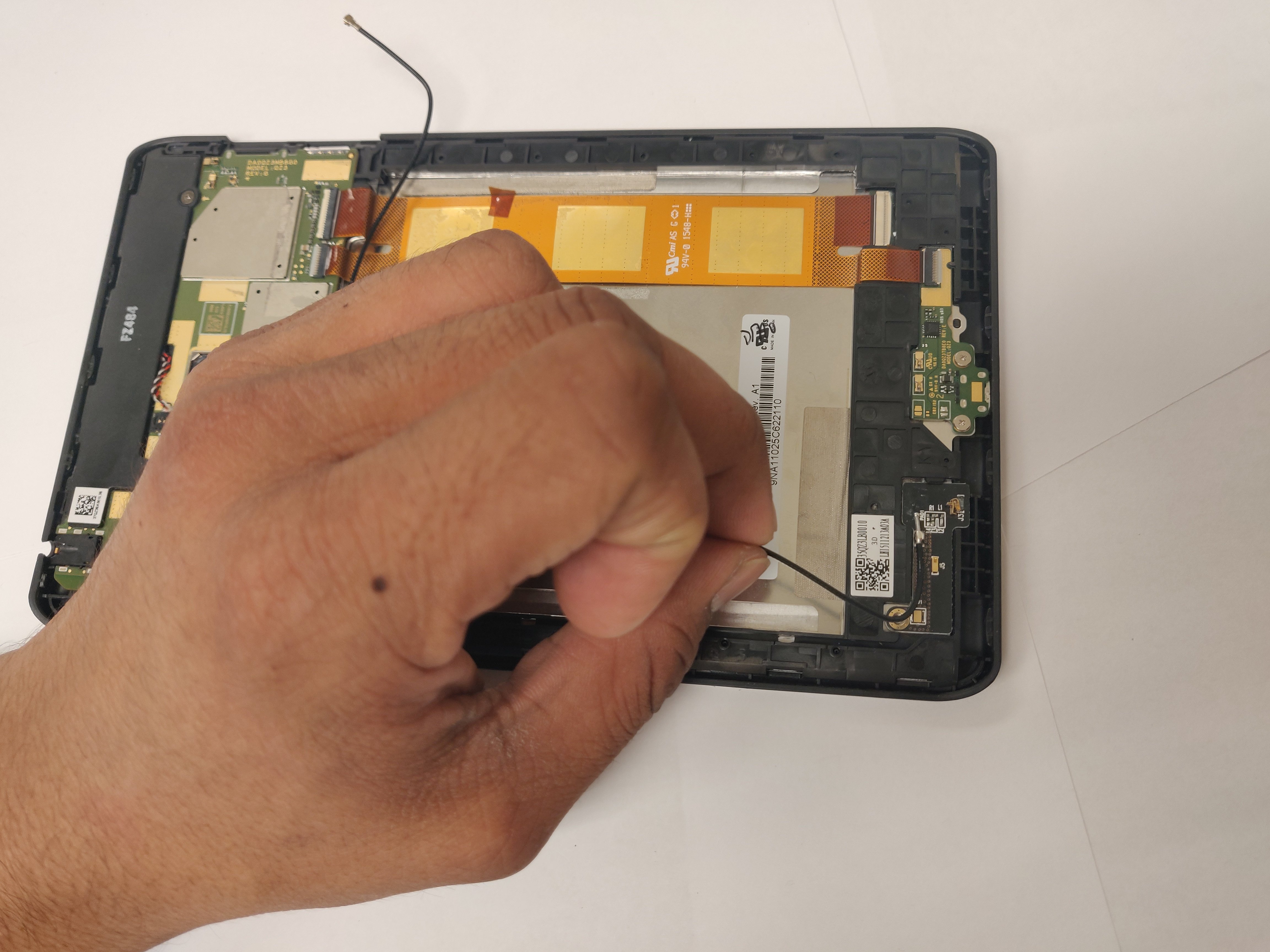
– Time to get started! Remove the rear cover to begin your repair journey.
– Reassembly tip: now’s a great time to test your phone before sealing it up. Power it on, make sure everything is working smoothly, then power it back down before continuing.
– Let’s take a quick break to test your phone. Turn it on and check that all features are working as they should. Once you’ve confirmed, power it back down and get ready to finish reassembling.
– Almost done! Follow our guide to apply new adhesive and securely install your rear cover. If you need help, you can always schedule a repair.
Step 22


Don’t go crazy with the heat, just warm the flash up a bit! Those battery and nearby components are sensitive to overheating, so keep things chill. 😉
For those who like to get their hands warm and toasty, grab a hair dryer or heat gun, and let’s give that flash a little love!
– Get ready to warm up that flash unit! Use a heated iOpener to apply some love for a minute to soften up the adhesive holding it to the logic board cover. It’s like giving your phone a mini spa treatment!
Tools Used
Step 23


Watch out for that delicate flash cable! It’s super fragile, so let’s keep it safe and sound while we work our magic.
– Gently slide your pick beneath the right edge of the flash to break the adhesive that’s holding it to the cover. You’ve got this!
Step 24


– If the copper tape decided to take a vacation with the flash, don’t fret! Grab some tweezers or your fingers and gently clear away the black foam residue from the logic board cover like you’re tidying up your workspace.
Tools Used

Step 25


Hey, be careful not to poke the battery with your tool! Just a gentle touch here. Remember, we’re all about keeping things smooth and safe.
If the copper tape is still hanging out on the logic board cover and you’ve got a shiny new replacement ready to go, it’s time to say goodbye to the old tape!
– Let’s get this repair started! Apply some heat to the underside of the flash with a heated iOpener for about a minute.
– Now it’s time to get a little delicate – hold the neck of the flash cable steady and use your trusty tweezers to carefully peel and remove the copper tape from the flash unit.
Step 26


The Pixel 7a has a knack for Torx Plus screws, but don’t fret—your trusty standard Torx drivers might just do the trick! If you’ve got a kit with standard Torx bits lying around, grab the T2 bit to tackle those 1IP Torx Plus screws, and reach for the T3 Torx bit for the 3IP Torx Plus screws. Remember to keep that downward pressure steady to avoid stripping those screws like a pro!
– Grab that 3IP Torx Plus driver and remove the thirteen 4.3mm screws holding down the logic board cover. You’ve got this!
– Switch to the 1IP Torx Plus driver and take out the 1.5mm screw securing the right edge of the cover. Almost there!
Step 27


– Time to get this repair started! Insert an opening pick between the bottom right corner of the logic board cover and the frame – it’s like a little puzzle piece that helps you get inside.
– Gently pry up to release the clip that’s holding the cover in place. You’re making great progress!
Step 28


– Gently raise the top edge of the logic board cover and carefully slide the flash unit through its designated cutout. You’re doing great!
– As you put everything back together, make sure to guide the flash back through its cutout while lowering the logic board into place. Teamwork makes the dream work!
Step 29


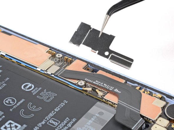
– Alright, let’s take this wireless charging assembly for a spin. Time to remove it!
Step 30

– Grab your trusty 1IP Torx Plus driver and unscrew that 1.5 mm screw holding the connector cover in place. You’ve got this!
– Now, with a gentle touch, use tweezers or your fingers to lift off the cover. Easy peasy!
– When it’s time to put everything back together, make sure to tuck the upper left corner of the cover under the hook on the logic board before securing it with its screw. You’re almost there!
Tools Used
Step 31

The Verizon model (G0DZQ) Pixel 7a comes with a bonus cable and connector for the 5G mmWave antenna. Unless we say otherwise, all other steps in this guide apply to both types of phones. Let’s get fixing!
Step 32


To reconnect a press connector, line it up with the socket and gently push down on one side until you hear that satisfying click. Then, press down on the other side. Don’t worry if it takes a few attempts to get it just right – it’s all part of the process!
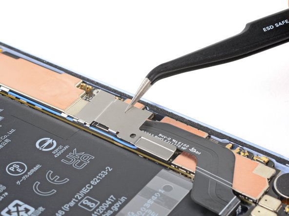
– Gently slide the flat end of your trusty spudger under the top edge of the battery press connector.
– Give it a little nudge straight up to pop that battery press connector loose.
Tools Used

Step 33

– Time to get started! Use your trusty 3IP Torx Plus driver to carefully remove the 4.3mm screw that’s holding the earpiece speaker in place on the frame.
Step 34


– Gently lift the bottom edge of the earpiece speaker up into the air.
– Carefully pull the speaker down toward the bottom of the phone to release the sneaky red gasket from its snug little home in the frame.
– Now, it’s time to take out the speaker!

Step 36


– Slide an opening pick into the top left corner of the antenna housing and gently nudge it between the housing and the frame.
– Lift up to pop those clips free and have the housing let go—it’s like a little dance move!
– When you put things back together, make sure to keep the graphite film out of the way as you slide the housing back in. You’ve got this!
Step 37


– Gently lift the bottom leg of the antenna housing and slide the top edge out from the frame with a little finesse.
– Now, go ahead and remove the housing with confidence!


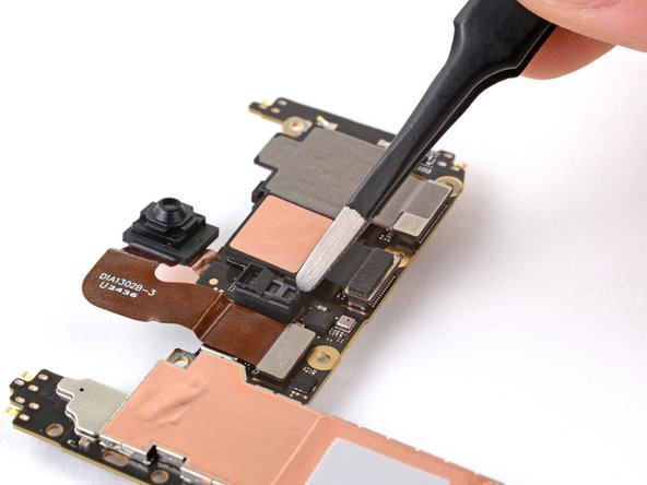
Step 39

– Grab that trusty iOpener and give it a little heat party on the front-facing camera for a solid minute. This will help melt that stubborn copper tape adhesive and make your life much easier!
Tools Used
Step 40


Watch out! The rear camera lenses are like delicate treasures—keep your fingers away from them!
If the tape is being stubborn, grab a sharp tool like angled tweezers and gently scrape up the edge until you can slip a pick underneath. Remember to be patient and take your time, and if you need help, you can always schedule a repair
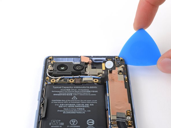
– Gently slide the tip of your trusty opening pick beneath the copper tape covering the front-facing camera.
– Carefully lift the tape away from the logic board, taking your time to avoid any surprises!
Tools Used
Step 41


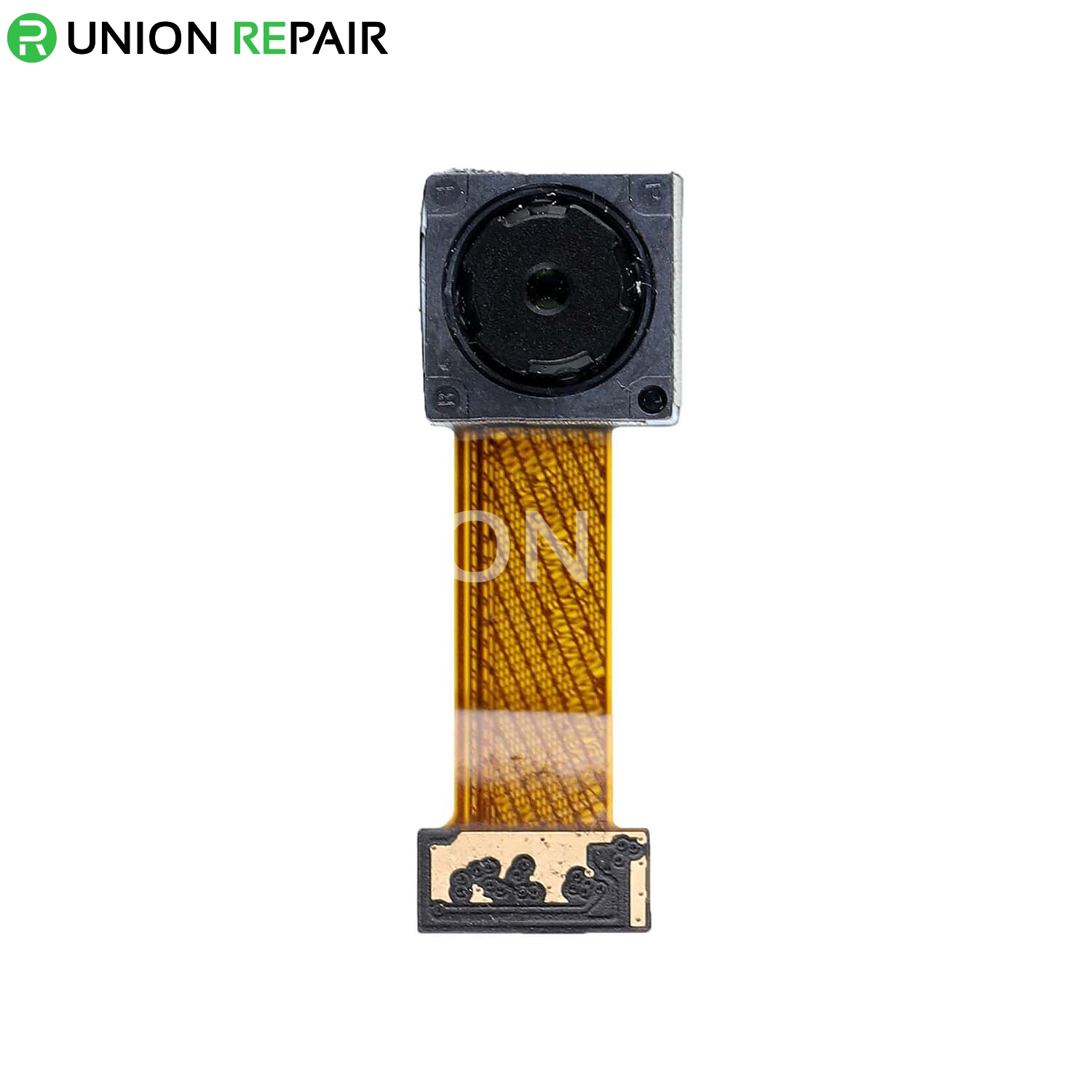
Watch your fingers and keep those tools away from the front-facing camera lens! It’s a sensitive little thing, so let’s give it some space.
If the pick doesn’t want to dance under the cable, give it a little warm-up with a hair dryer or heat gun to loosen the adhesive hiding underneath.
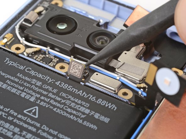
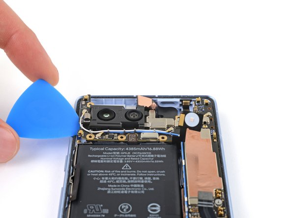
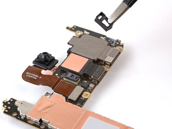
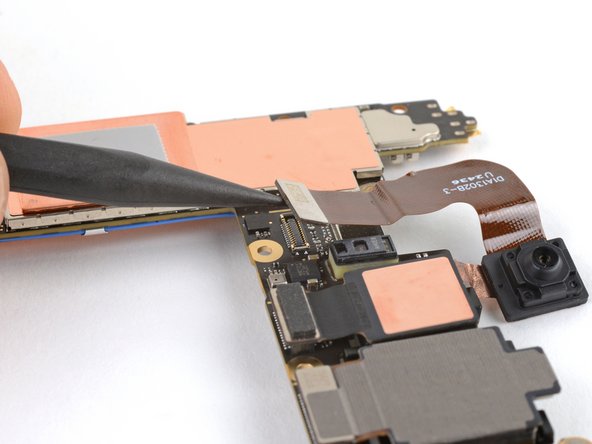
– Gently slide the tip of your opening pick into the space between the right edge of the front-facing camera cable and the frame. You’re doing great!
– Now, carefully maneuver your pick underneath the cable to break free the adhesive that’s holding it to the frame. You’re almost there!
Tools Used
Step 42

Keep those fingers clear of the rear camera lenses!
This connector handles the power button, volume controls, flash unit, and the upper microphone. It’s like the conductor of your device’s symphony, making sure everything plays in harmony!
– Use a spudger or your trusty fingernail to carefully pry up and release the press connector located just above the battery.
Tools Used
Step 43

– Let’s start by carefully sliding your opening pick between the top right edge of the logic board and the frame.
– Now, gently pry up to release the logic board from its snug little spot.
– Next, slide your pick into the gap near the white antenna cable and pry up the top left edge of the logic board. You’re doing great!
Step 44


The logic board is a bit of a diva, so handle it with care! Gently ease the lower edge away from the frame without bending it.
Hold your horses! Don’t completely detach the logic board just yet; it’s still hanging on to the frame by the screen cable.
Keep an eye on the flash, front-facing camera, and press connector—let’s make sure they don’t get stuck under the frame like a lost sock in the laundry!
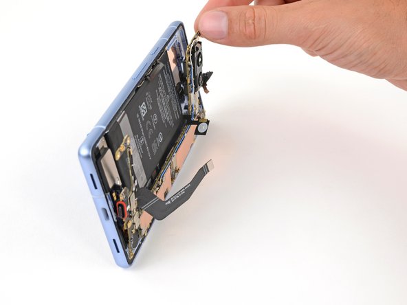
– Let’s get started by carefully lifting the top edge of the logic board from the frame.
– Next, gently pull the top edge of the logic board to the right, making sure the cutouts on the board clear the vibration motor and protrusions in the frame.
– As you pull the logic board, guide the charging port out of its recess in the frame – it’s like a little puzzle piece coming together.
– When it’s time to put everything back together, push the logic board toward the bottom of the frame and press the charging port down until it’s snug and even with its protrusion in the frame.
Step 45

Hey there! Just a heads up, the logic board might try to do a little dance and fall out of place during this part. Keep it nice and steady, but make sure not to grab it by the camera lenses or connectors—those are sensitive areas!
And let’s give those thermal pads on the underside of the logic board some space, shall we? Avoid touching them, as they like to stay comfortable!
If you don’t have a suction handle, no worries! Just find a sturdy object like a heavy box or a thick book and prop up your phone against it. You’ll be good to go!
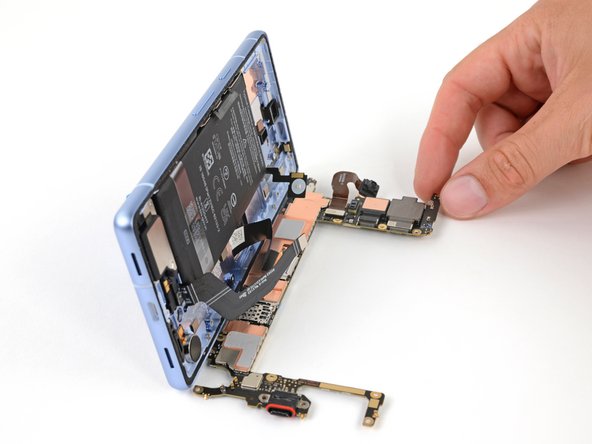
– Stick your suction handle to the left side of the screen, making sure the handle is facing down. We want to lift, not to level!
– Stand the phone up like it’s ready for a selfie; you’re doing great so far!
– Gently tilt the logic board down and lay it flat. If any pesky cables are in the way, don’t hesitate to move them aside.
Tools Used
Step 46


– Let’s get that screen connector cover off! Use your trusty 3IP Torx Plus driver to give those 2mm screws the boot.
– Time to ditch the cover. It’s free to go!
– Now, when you’re putting everything back together, be sure to hook the bottom edge of that cover into its slot on the logic board *before* you put the screw back in. You’ll be happy you did!
Step 47


– Time to get started! Use the flat end of your trusty spudger to carefully pry up and disconnect the screen press connector.
– Now, about that tricky cable – it can be a bit of a challenge to reconnect. If you’re having trouble, try holding the neck of the cable in place with some tweezers and aligning it over the socket before gently pressing down to secure it. You got this!


Step 49

Be careful not to touch the sensor with your fingers or any tools, let’s keep it clean and precise!
– If the rubber gasket for the front sensor is stubbornly hanging onto the frame or has decided to take a little detour, gently remove it and put it aside for a moment.
– When you’re ready to piece everything back together, place that gasket right over the front sensor on the logic board, ensuring the smaller cutout is aimed towards the top.
Step 50

– As you put everything back together:
– If you’re reusing your logic board and that thermal pad has seen better days, go ahead and peel off the old one, give the surface a good clean, and slap on a fresh thermal pad.
– If you’ve got a shiny new logic board that didn’t come with a thermal pad already in place, now’s the time to get that new thermal pad on there!

Step 52


– Ready to put your device back together? Just follow the steps in reverse order!
– Want to give your device a check-up? Run a quick diagnostics test with the Pixel Diagnostic tool. You can find it here: https://www.google.com/search?q=Pixel+Diagnostic+tool.
– Don’t forget, always recycle your old tech responsibly. Take your e-waste to an R2 or e-Stewards certified recycler.
– Did things not go exactly as planned? No worries! Try a little basic troubleshooting, or get some advice from our awesome Answers community. schedule a repair
– Didn’t quite finish the guide? No sweat! Just click ‘Cancel’.
–
Success!