DIY Guide: How to Replace iPhone 6s Plus Back Cover
Duration: 120 min.
Steps: 38 Steps
Welcome to your DIY adventure! In this guide, we’ll walk you through the process of replacing that worn-out back cover on your iPhone 6s Plus. Whether your back cover is looking a bit bent or scratched, or if your rear camera is struggling to snap clear photos due to a scratched lens, we’ve got you covered. So grab your tools, and let’s get started on bringing your phone back to life! If you ever feel overwhelmed, don’t hesitate to schedule a repair with us.
Step 1
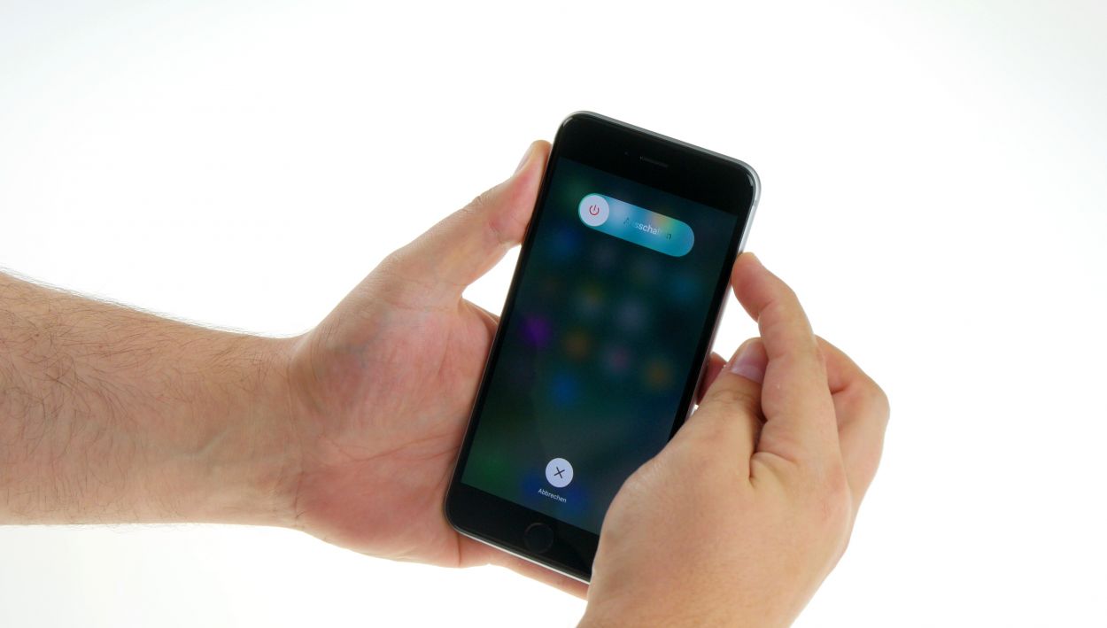

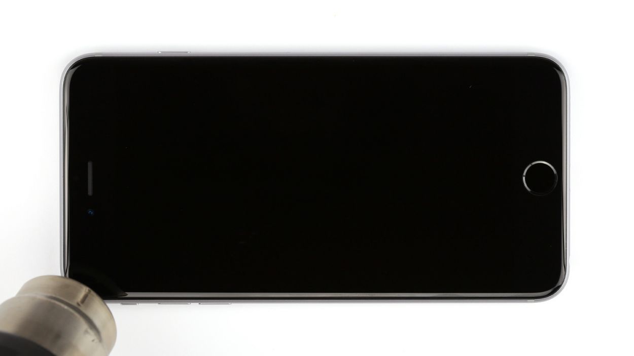
– First things first, let’s give your iPhone a little break! Power it down completely to keep it safe during the repair. Just press the standby button for about three seconds until you see that handy slider pop up.
– Now, slide that slider from left to right. Your iPhone will gracefully shut down, which might take around ten seconds. You’re doing great!
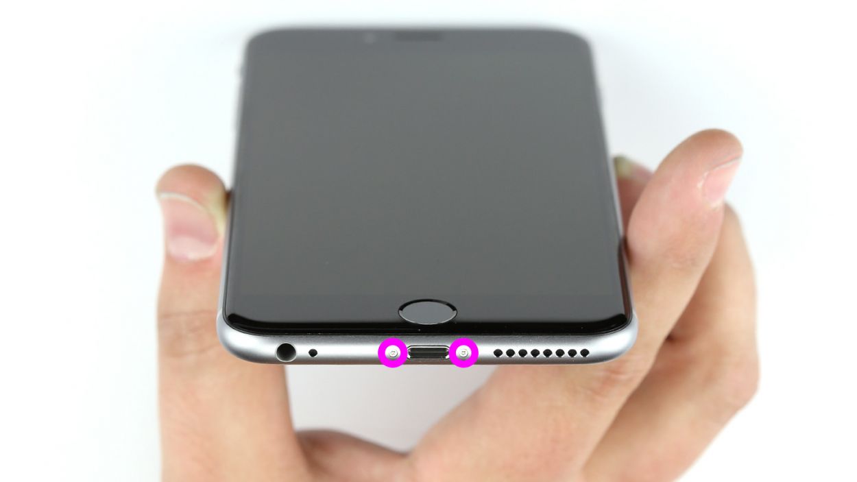
Step 2

– Grab your trusty pentalobe screwdriver because it’s time to unlock your iPhone 6s Plus!
– Carefully remove the two pentalobe screws located at the bottom of the enclosure, one on each side of the Lightning connector. Remember to keep those screws safe in the same container – 2 x 3.3 mm pentalobe screws are on the line!
Step 3

Watch out for flying glass shards! Let’s keep those fingers safe while we work on your device.
– Lay your iPhone 6s Plus down on a soft, clean surface to keep that back looking fresh and scratch-free!
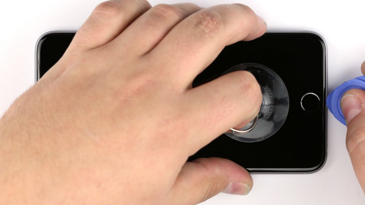
– To lift the display, you’ll want to grab a suction cup, a hard plastic pick, and a heat gun. If your screen looks like it’s been through a battle, cover it with packing tape first to avoid any glass surprises. Safety first, right?
– The screen is just a tad glued to the frame. Heat the edges of the display with your heat gun until they’re about 60°C (140°F) to loosen it up.
– Place the suction cup over the Home button if you can, or right next to it. While you gently pull up with the suction cup, use the hard plastic pick to press down on the aluminum frame. Slide that pick between the frame and the display, and don’t worry if it takes a few tries—persistence is key!
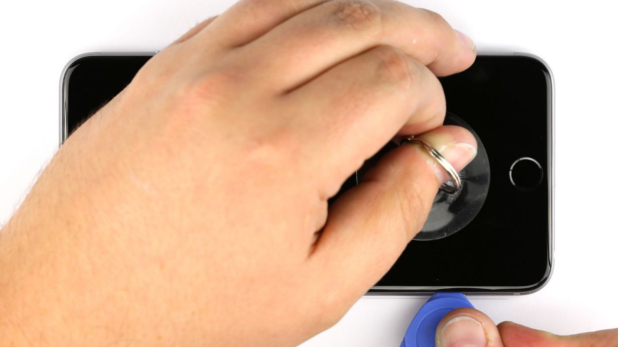
– Once you see a little gap forming, you can gently twist the pick to open it up more.
– When you can lift the display a few millimeters, carefully work your way around the edges until it’s loose on both sides. Feel free to give those outer edges a little heat if you need to.
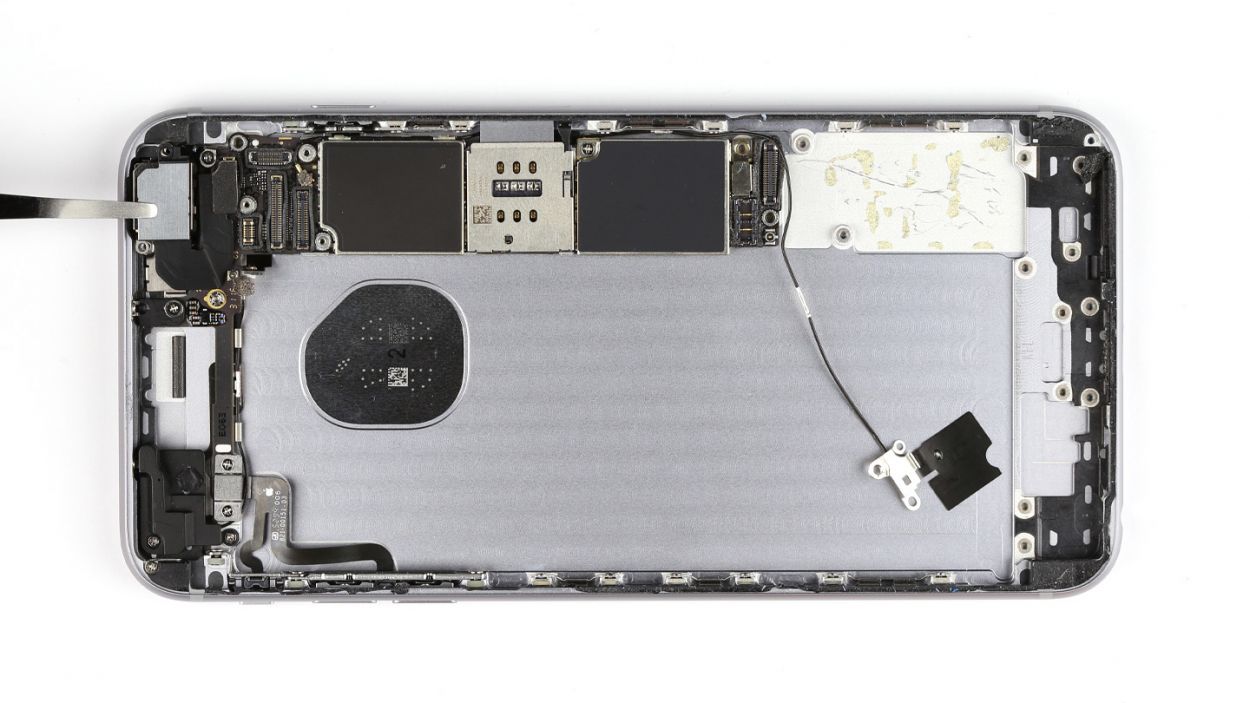
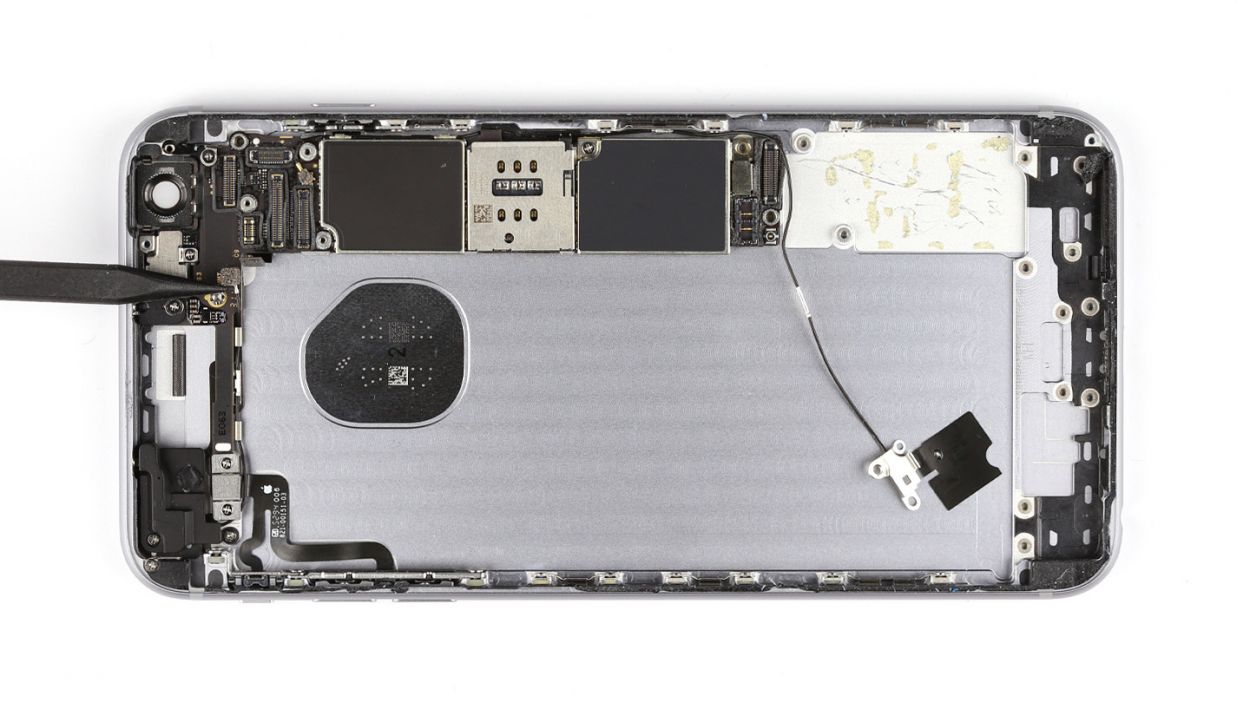
Step 4


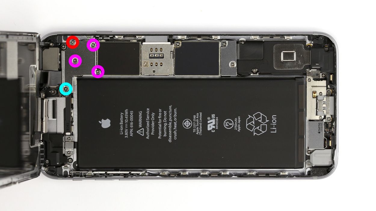
– First, let’s tackle those two Phillips screws and gently lift off the silver cover. You’re looking for 1 x 2.0 mm Phillips screw and 1 x 2.9 mm Phillips screw—don’t lose them!
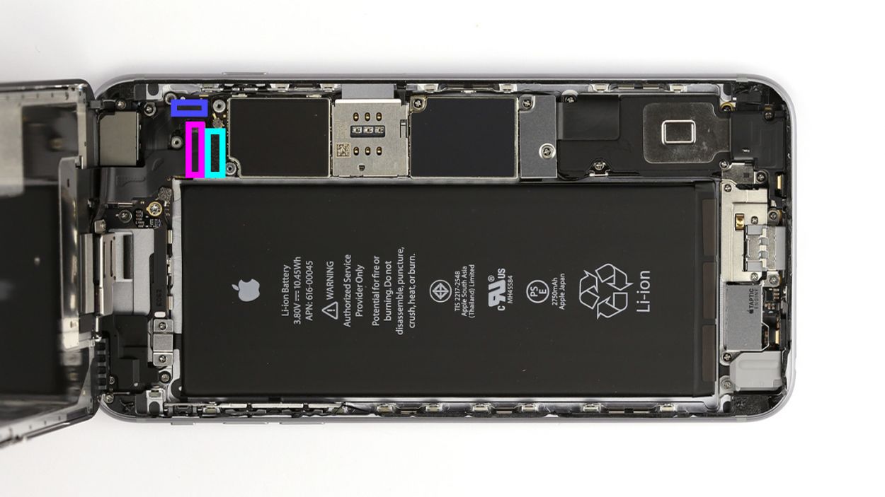
– Next up, grab your trusty spudger and carefully disconnect the lower connector for the battery contact, antenna, and Lightning connector. You’ve got this!
Step 5

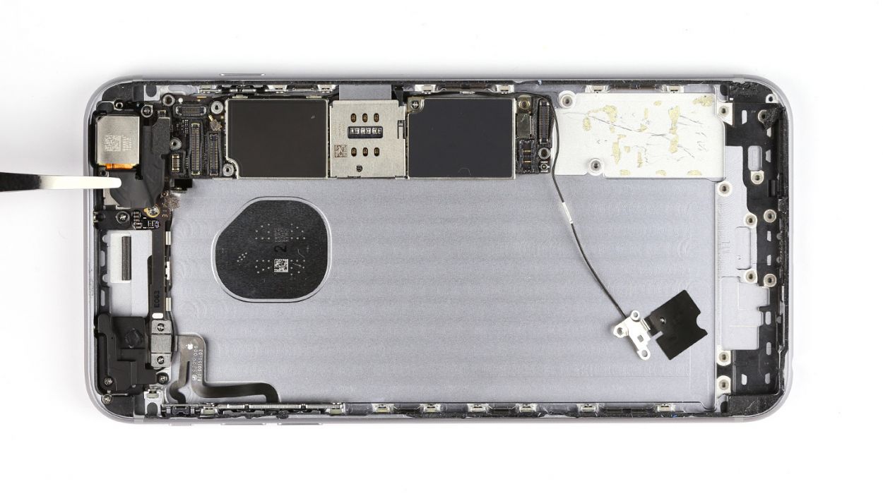
– Alright, let’s kick things off! First, grab your Phillips screwdriver and remove those five screws from the silver cover. Make sure to keep them all in one container so they don’t go wandering off. Once that’s done, gently lift the cover off like a pro!
– Next, it’s time to disconnect those three overlapping connectors. Follow the order shown below and take it easy! Use the pointed tip of your spudger to carefully lift each contact from just below. You’ve got this! Here’s what you’ll be disconnecting: Touch ID cable, Front camera/sensor/earpiece/ambient microphone, and the Display.
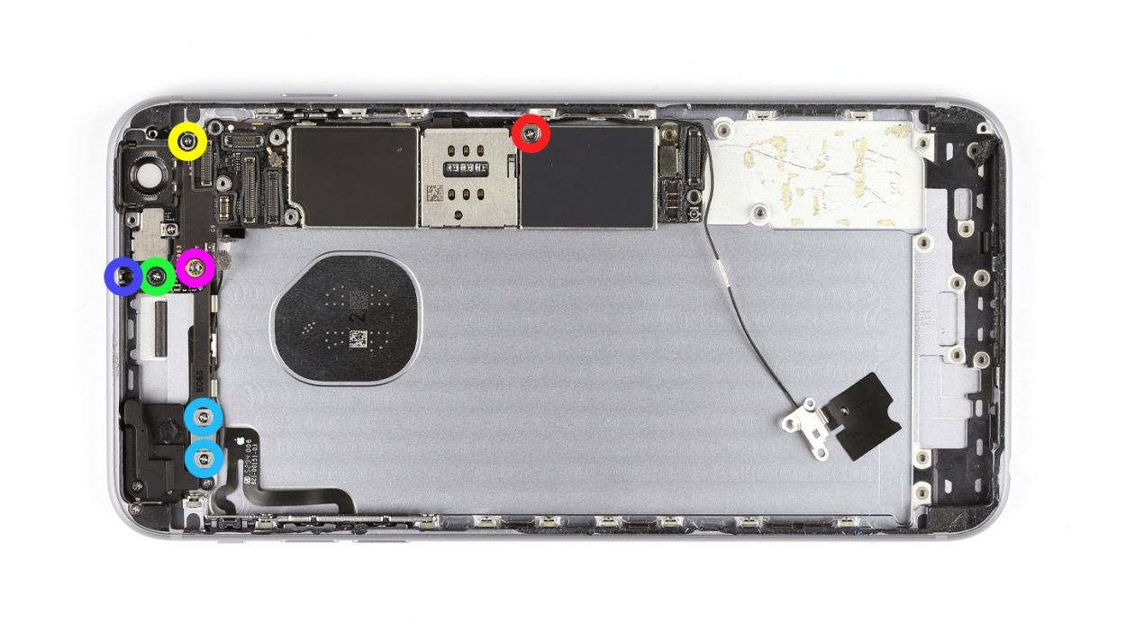
Step 6

– Underneath a plate lies the Taptic Engine’s contact, just waiting to be freed! Start by unscrewing those three screws from the plate: 1 x 2.6 mm Phillips screw and 2 x 3.3 mm Phillips screws. You got this!
– Once the screws are out, gently lift the plate away and keep it with the screws. You’re making great progress!
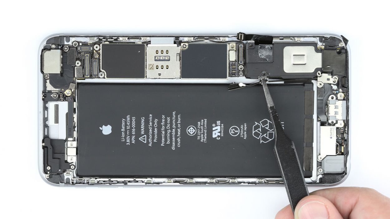
Step 7

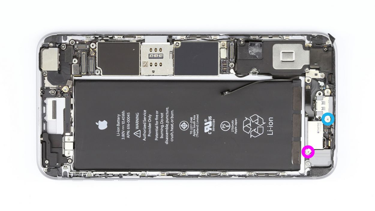

– Disconnect the contact.
– Unscrew the two screws that hold the Taptic Engine in place.1 x 2.1 mm Phillips screw1 x 3.0 mm Phillips screw
– Remove the Taptic Engine.
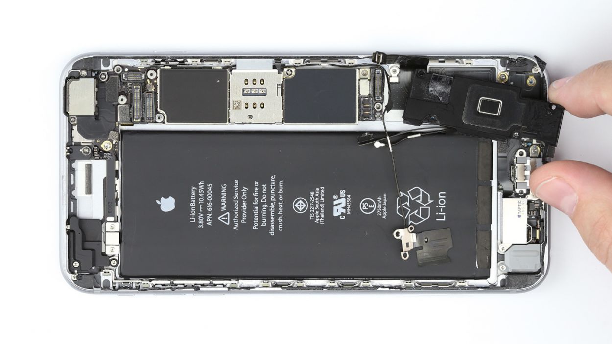
Step 8


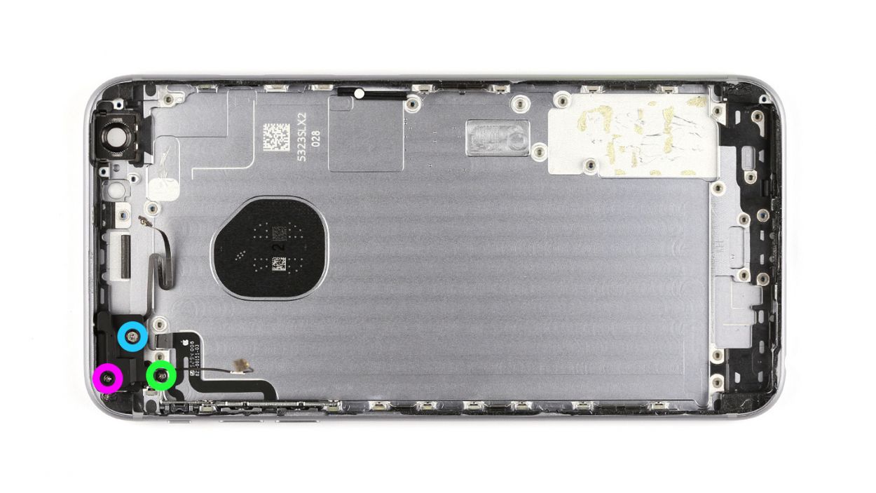
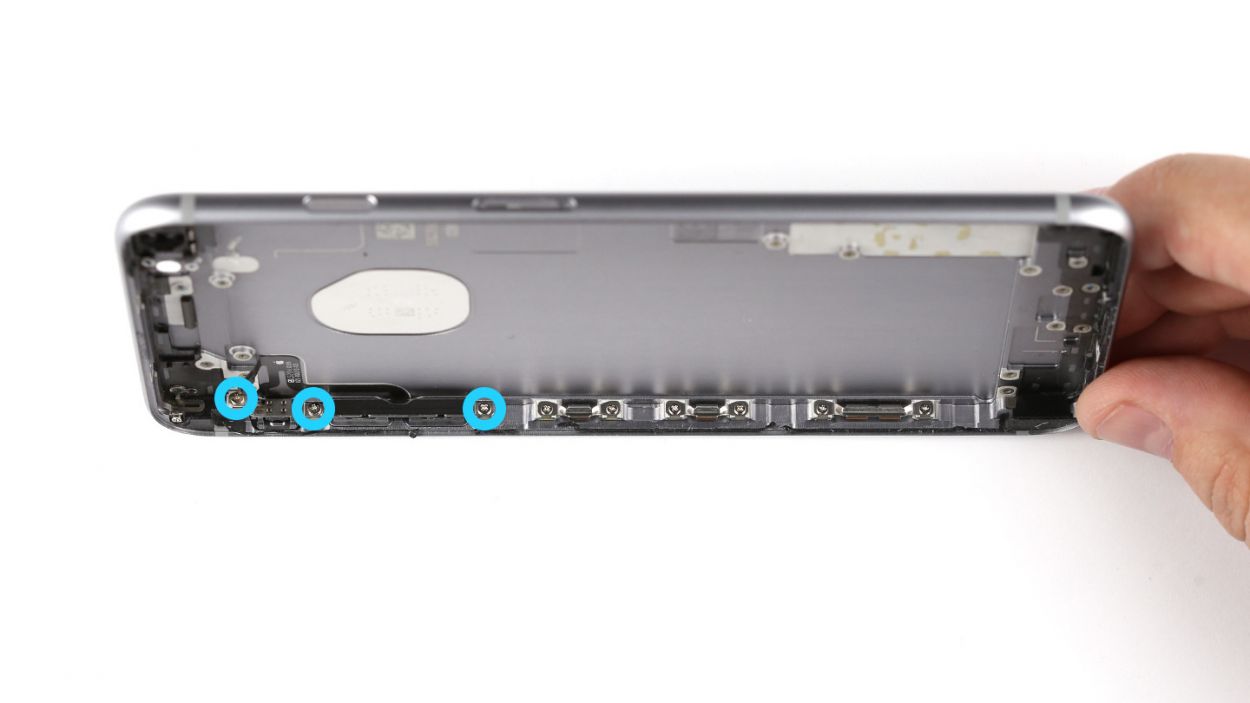
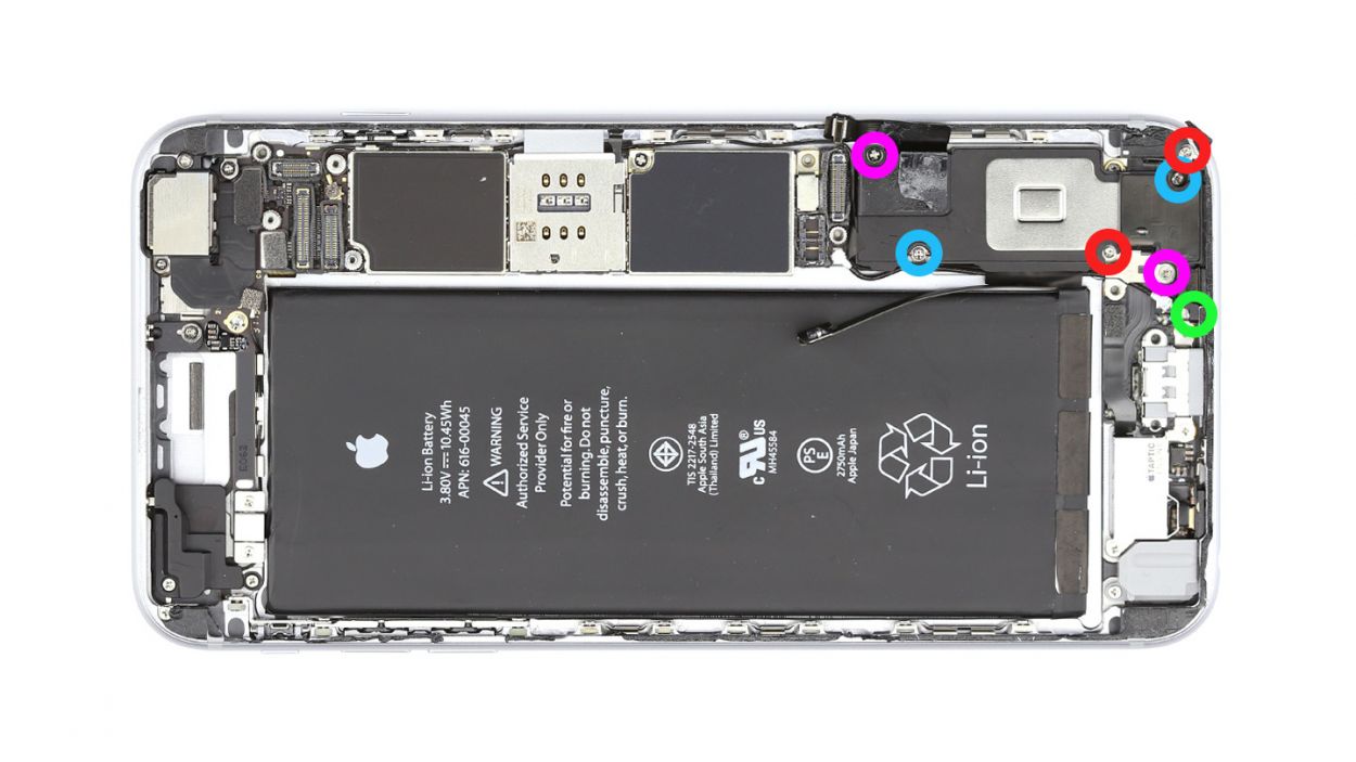
– Let’s get those seven Phillips screws out of the way so we can free the speaker! Make sure to keep them organized in different containers—trust us, future you will thank you! Here’s the lineup: 2 x 2.2 mm Phillips screws with large heads, 2 x 2.6 mm Phillips screws, 2 x 1.5 mm Phillips screws, and 1 x 2.4 mm Phillips screw (the angled one!).
– Now, gently move the antenna cable to the side and place the cable guide with the 2.6 mm Phillips screws. We’re almost there!
– Grab your trusty steel spatula and carefully detach the antenna from the speaker. You’re doing awesome!
– Use the flat end of the spudger to leverage that speaker out. Just a little nudge and it should come right out!
– And voilà! You’ve successfully removed the speaker. Keep up the great work!
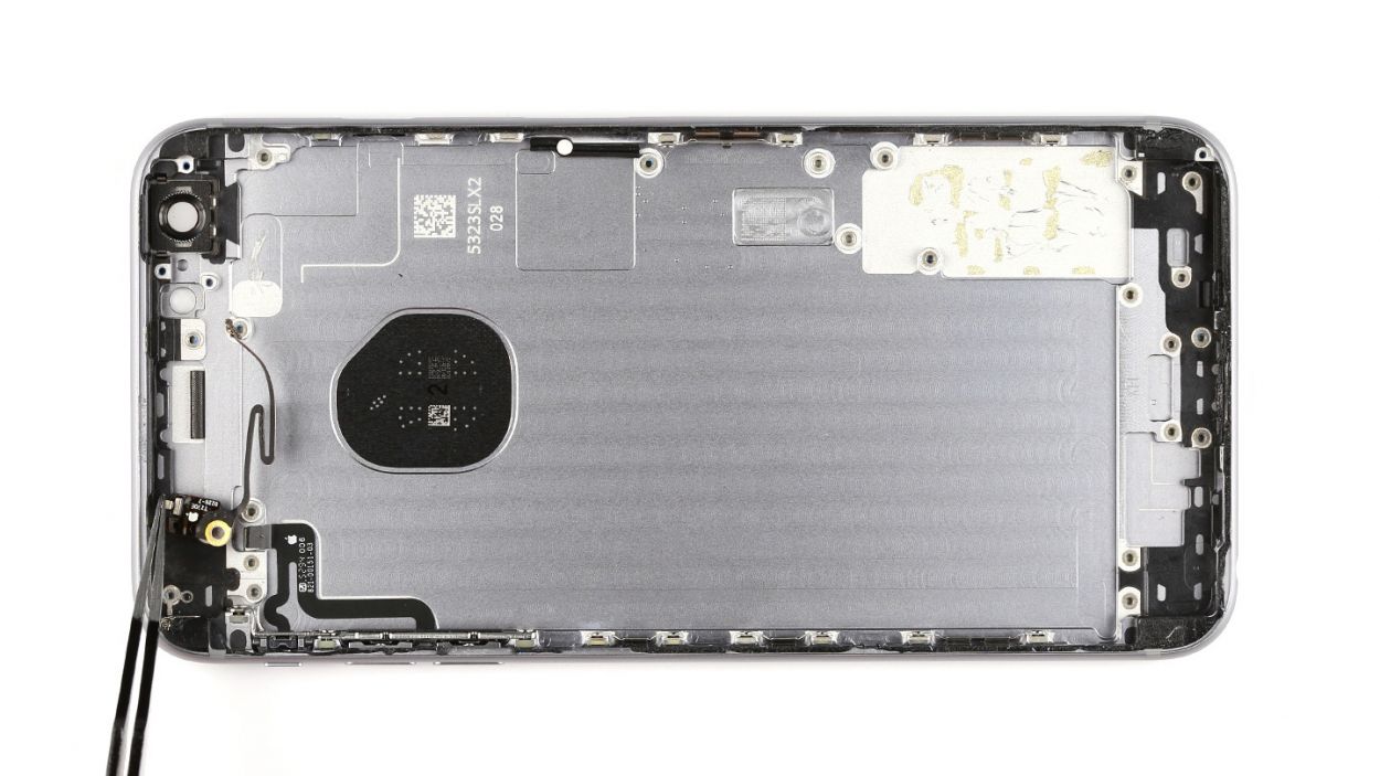
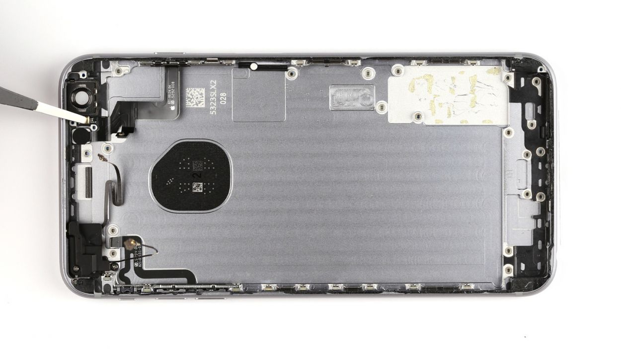
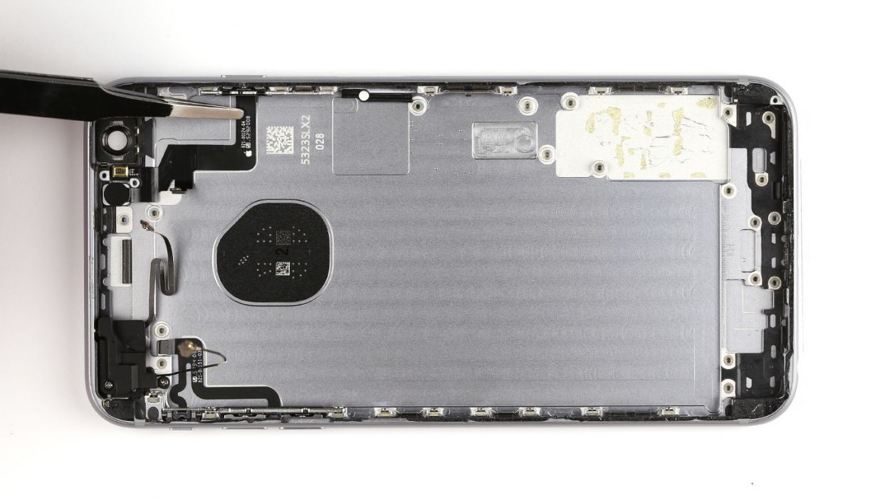
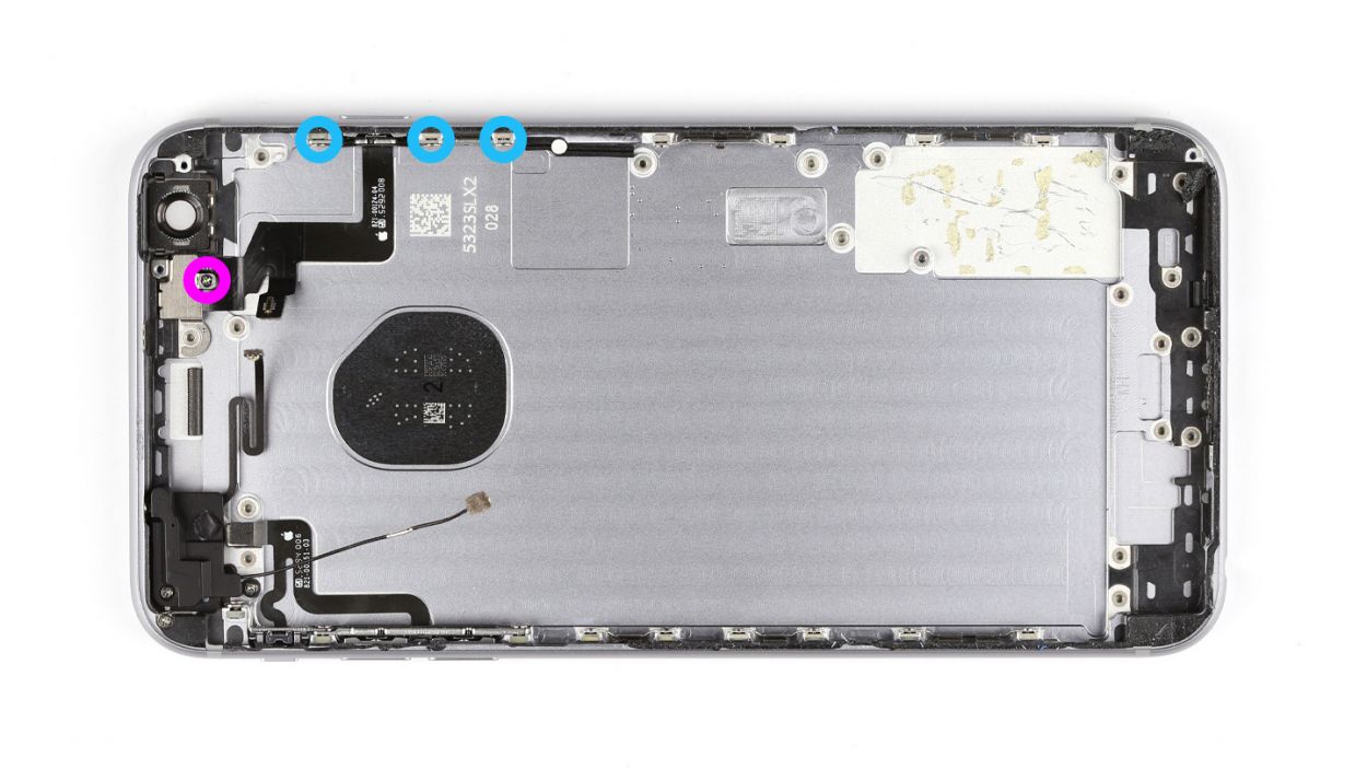
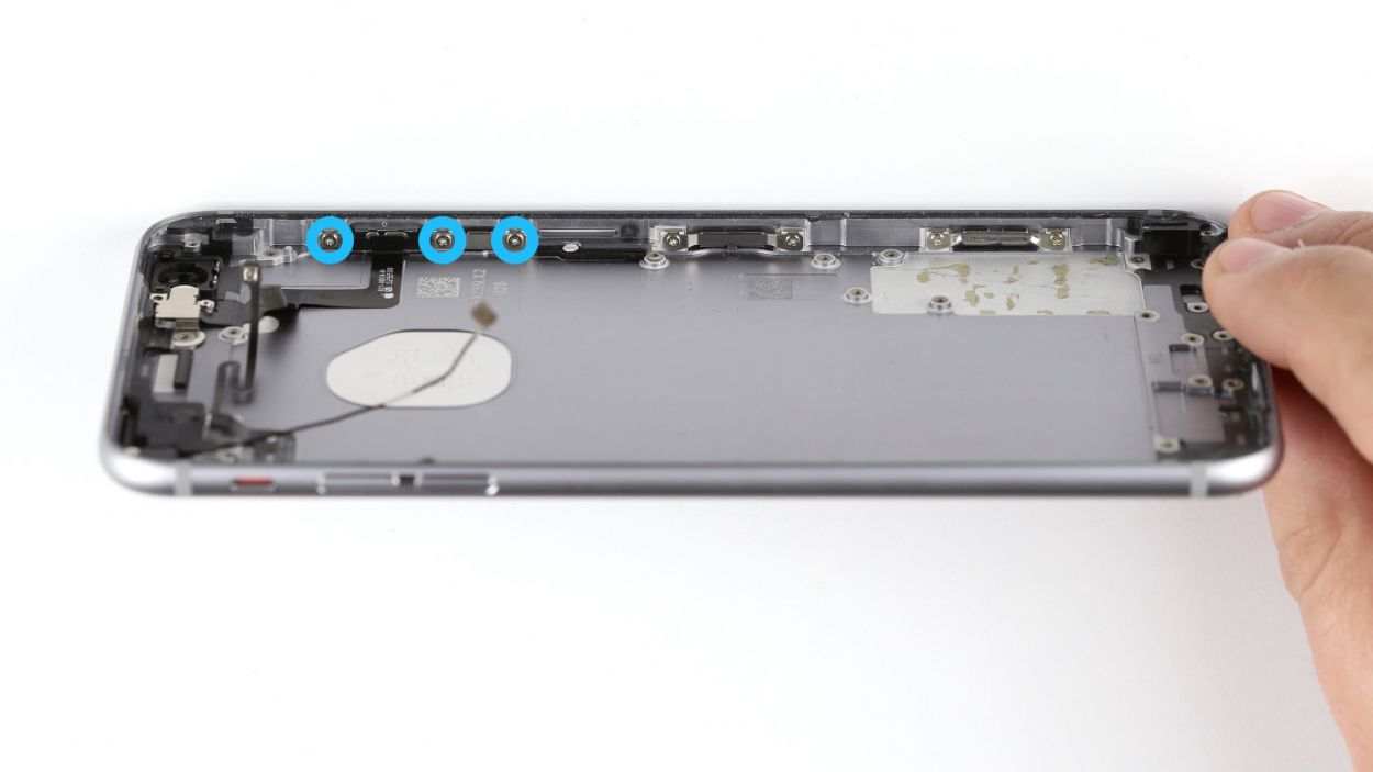
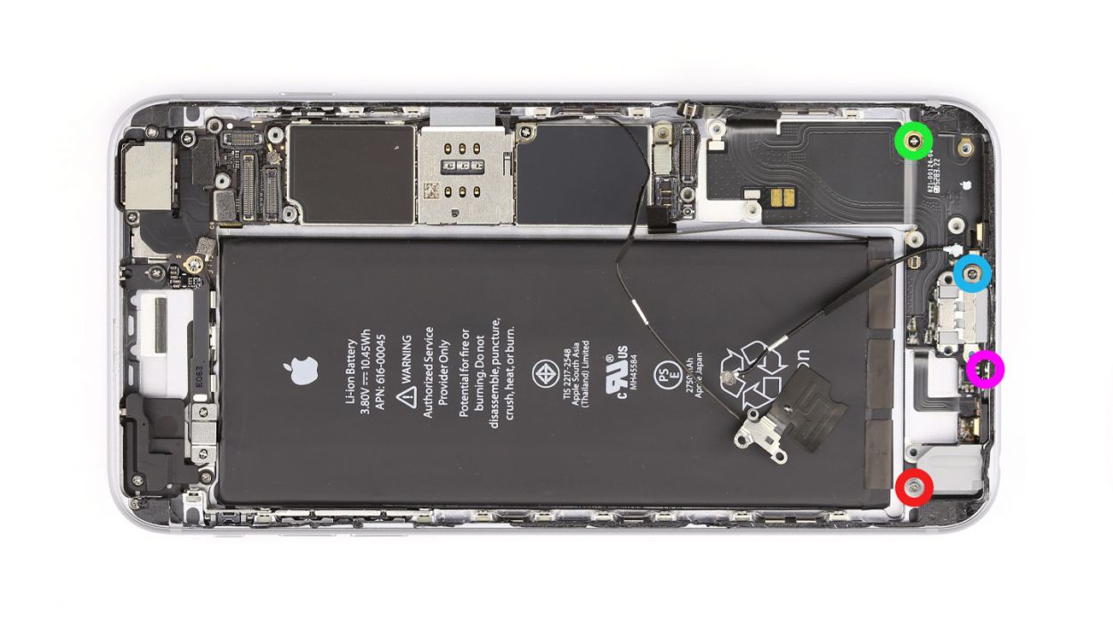
Step 9


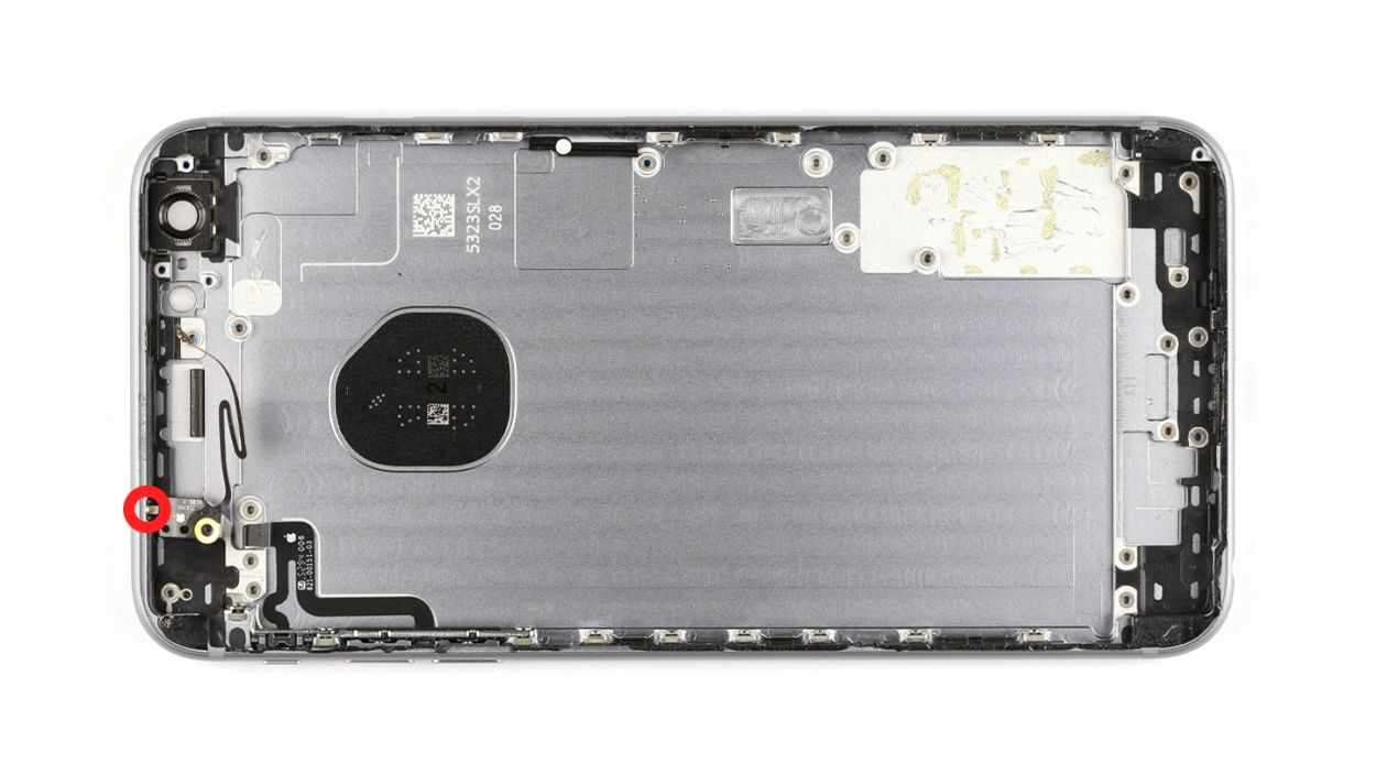
– Alright, let’s tackle those four Phillips screws! Make sure to stash them in different containers so you can keep track of them later. Here’s the lineup: 1 x 3.0 mm Phillips screw, 1 x 1.1 mm Phillips screw (the angled one), 1 x 1.8 mm Phillips screw, and 1 x 1.3 mm Phillips screw.
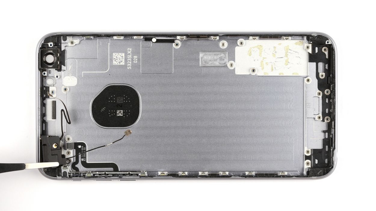
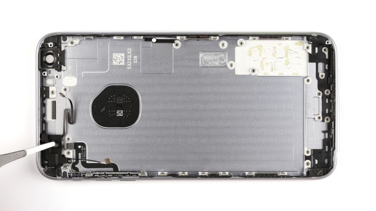
– Next up, grab your trusty spudger and use its pointed tip to gently detach the headphone jack and those two shiny gold microphones. You got this!
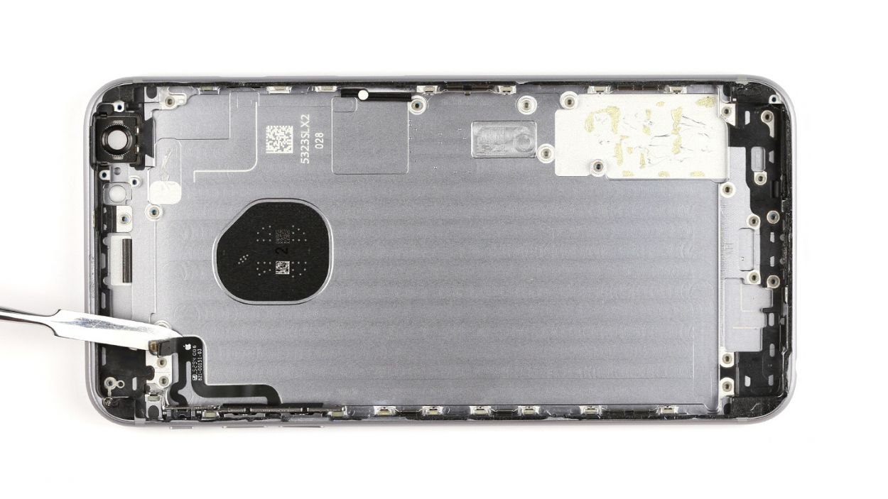
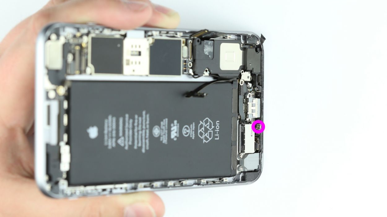
Step 10

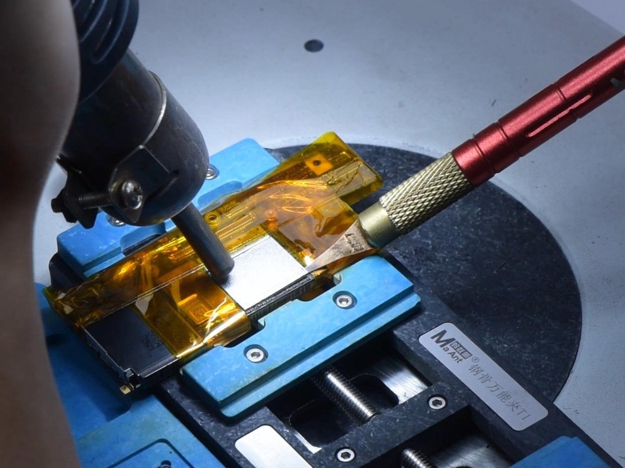
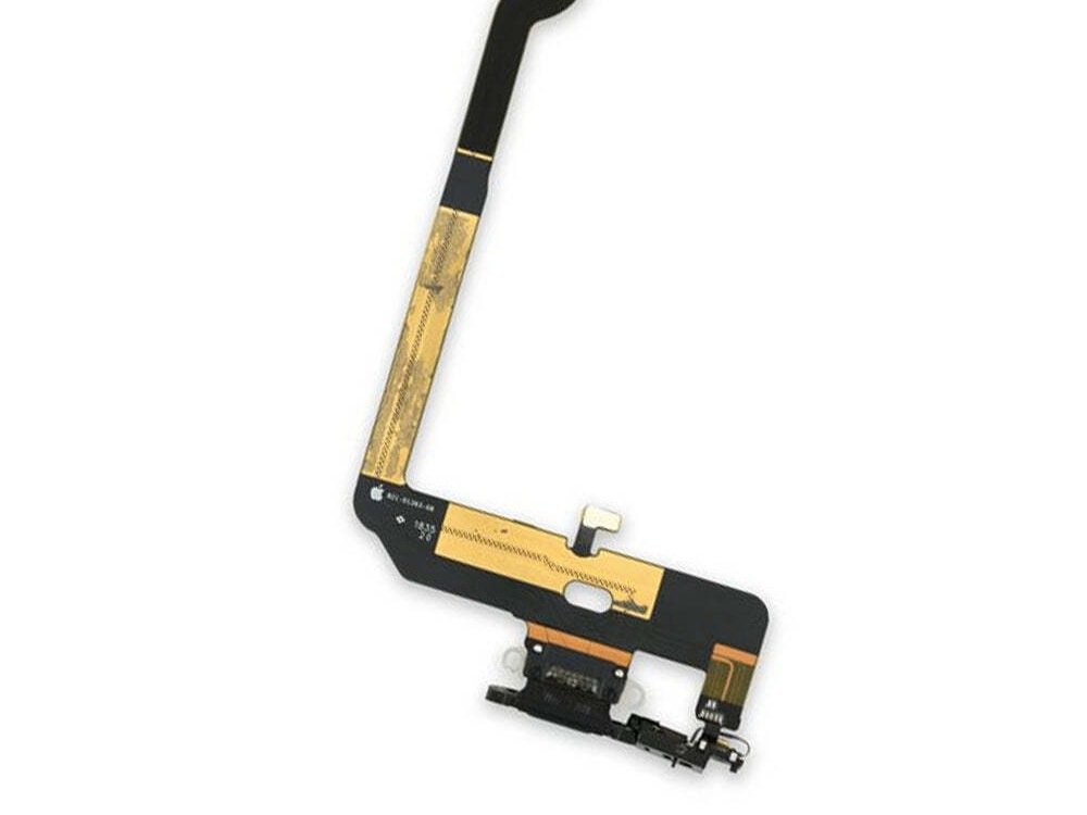
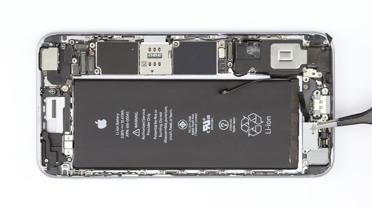
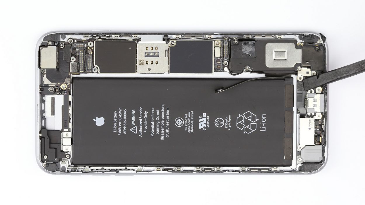
– Grab your trusty steel spatula and gently disconnect that Lightning connector like a pro!
– Slide the steel spatula under different sections of the flexible flat cable, giving it a little nudge.
– With a careful touch, use your fingers or tweezers to remove that ribbon cable. You’ve got this!
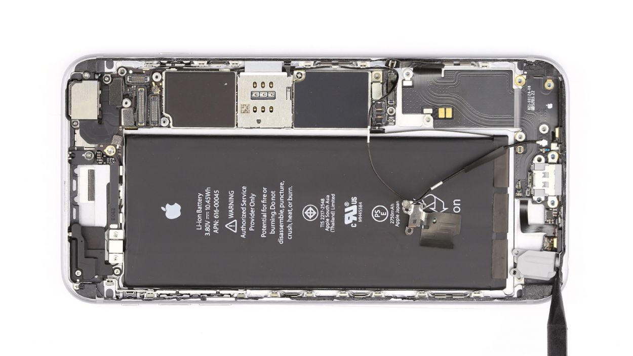
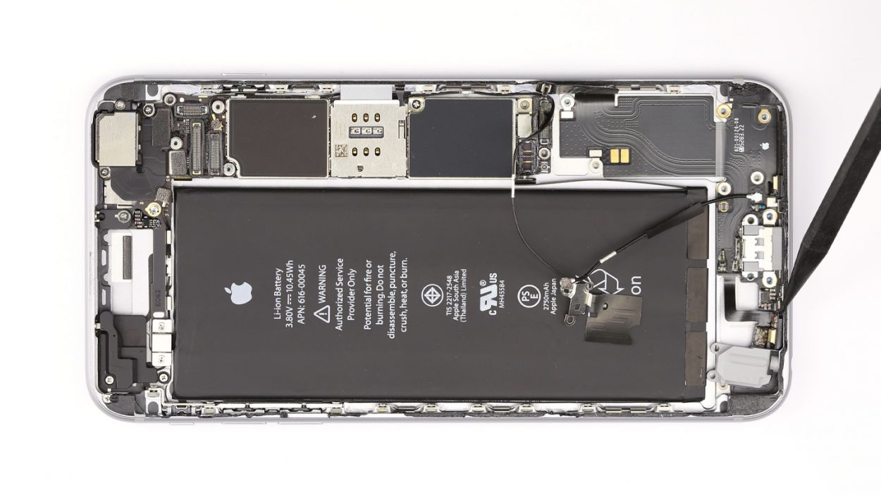
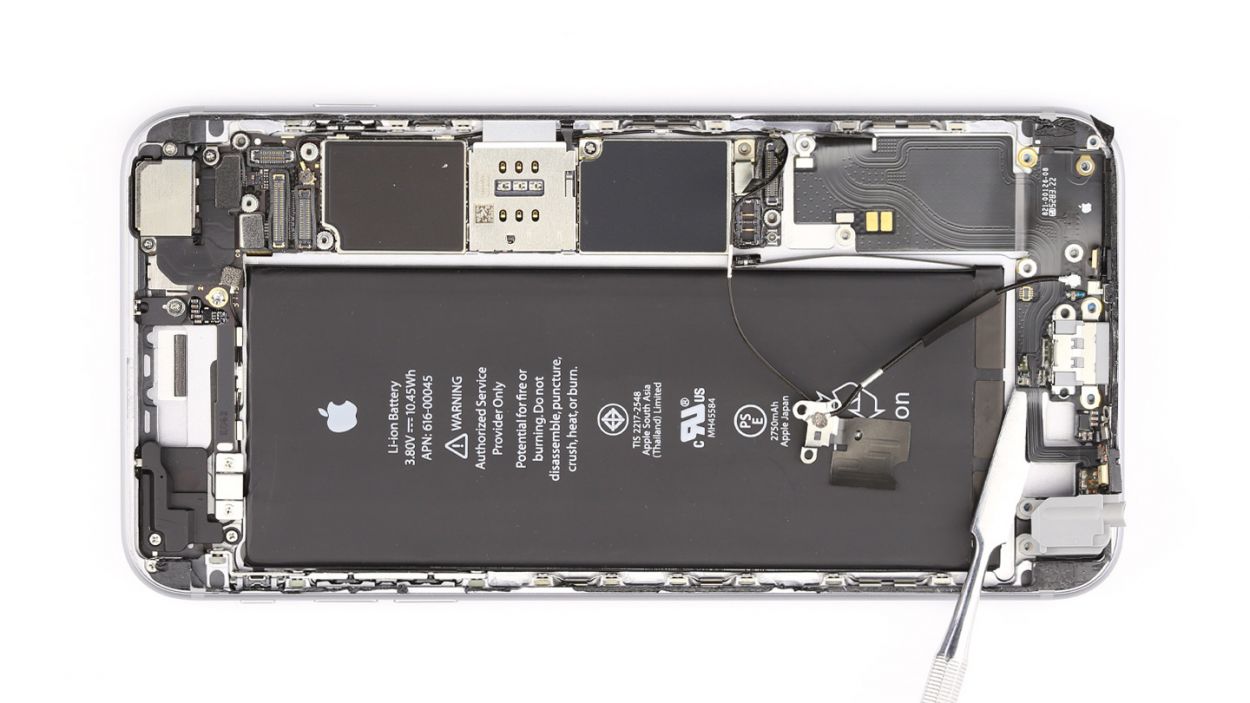
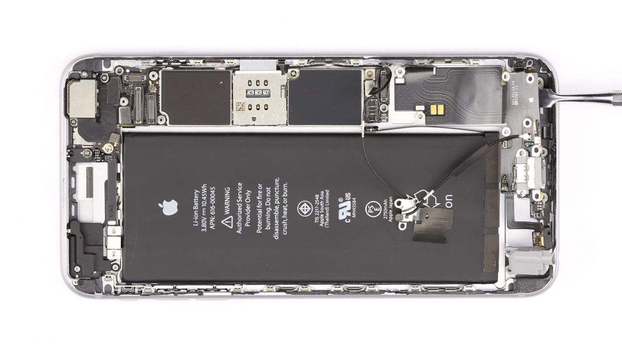
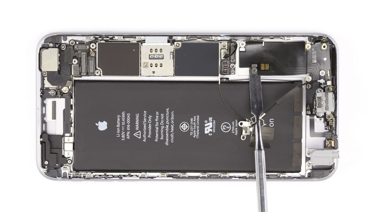
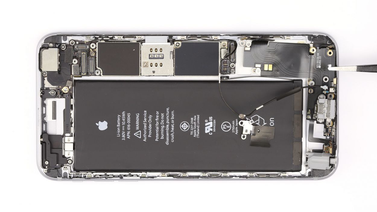
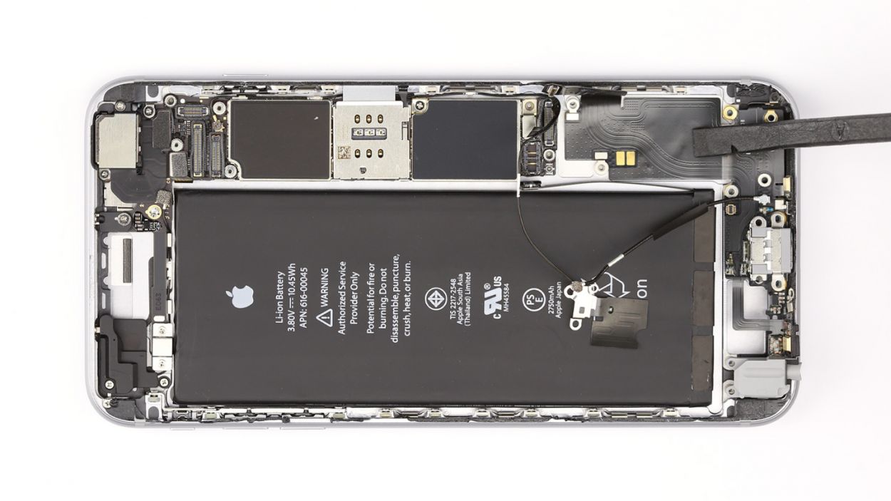
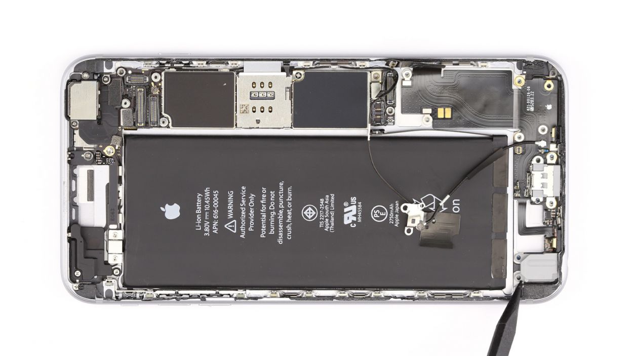
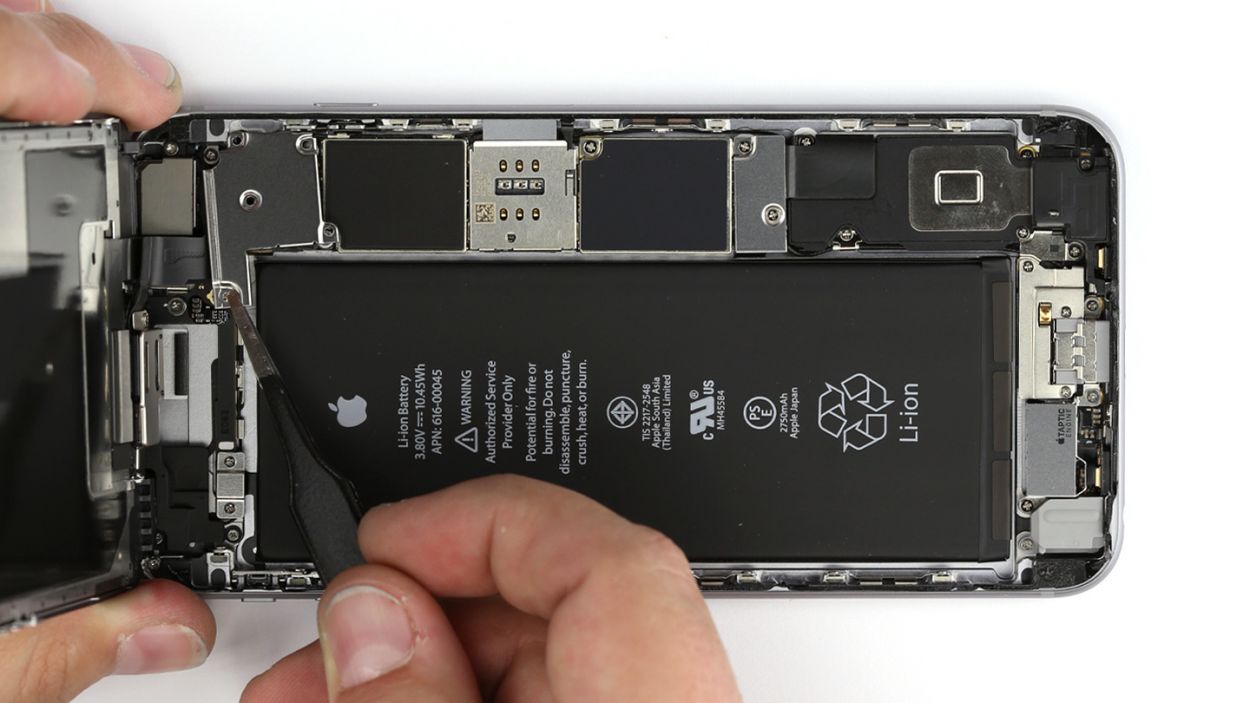
Step 11


– The battery is held snugly in place by three adhesive strips. Grab your tweezers and gently peel away the three black ends of those strips from the battery.
– Take your time as you pull off the adhesive strips. If you rush, they might tear, and we wouldn’t want that!
– Now, go ahead and lift out the battery. You’re doing great!
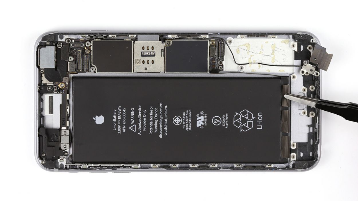
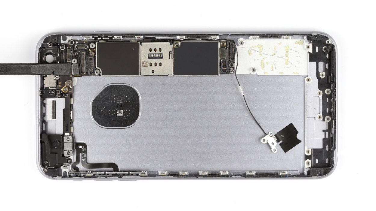
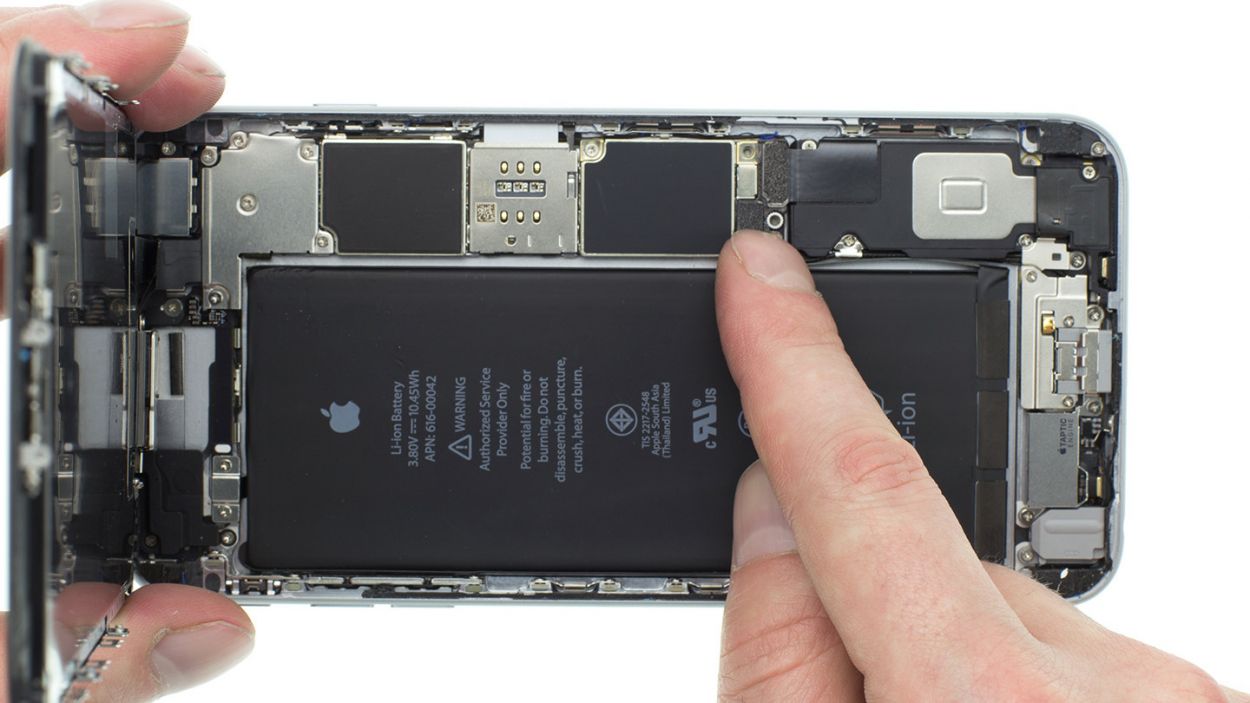
Step 12


The silver cover is just a little stuck to the camera—no biggie! Just a gentle nudge should do the trick.
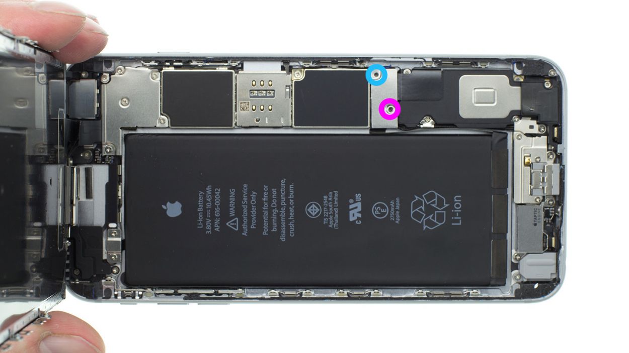
– Let’s start by gently disconnecting the camera connector! Use your spudger and slide it just below the contact, then give it a little lift.
– Next, it’s time to unscrew the two Phillips screws holding the camera cover in place. You’ve got one 2.1 mm Phillips screw and one 1.8 mm Phillips screw—keep them safe!
– Now, grab that spudger again and carefully detach the camera. You’re doing great!
– Finally, it’s time to remove the camera. Just a heads up, the silver cover is a bit sticky, but a gentle tug will do the trick!
Step 13
– You can grab your trusty SIM Tool or even a paperclip to pop out that SIM card tray. Just give a little push into the tiny hole on the tray, and voilà, it should come right out!
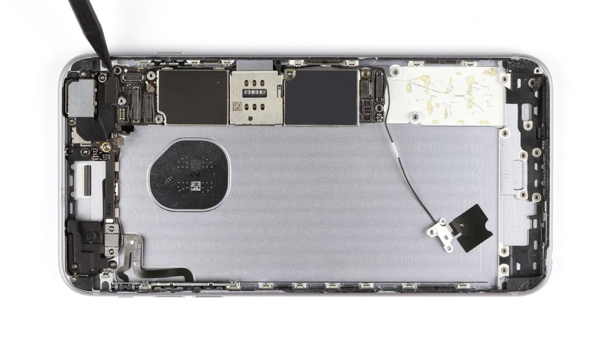
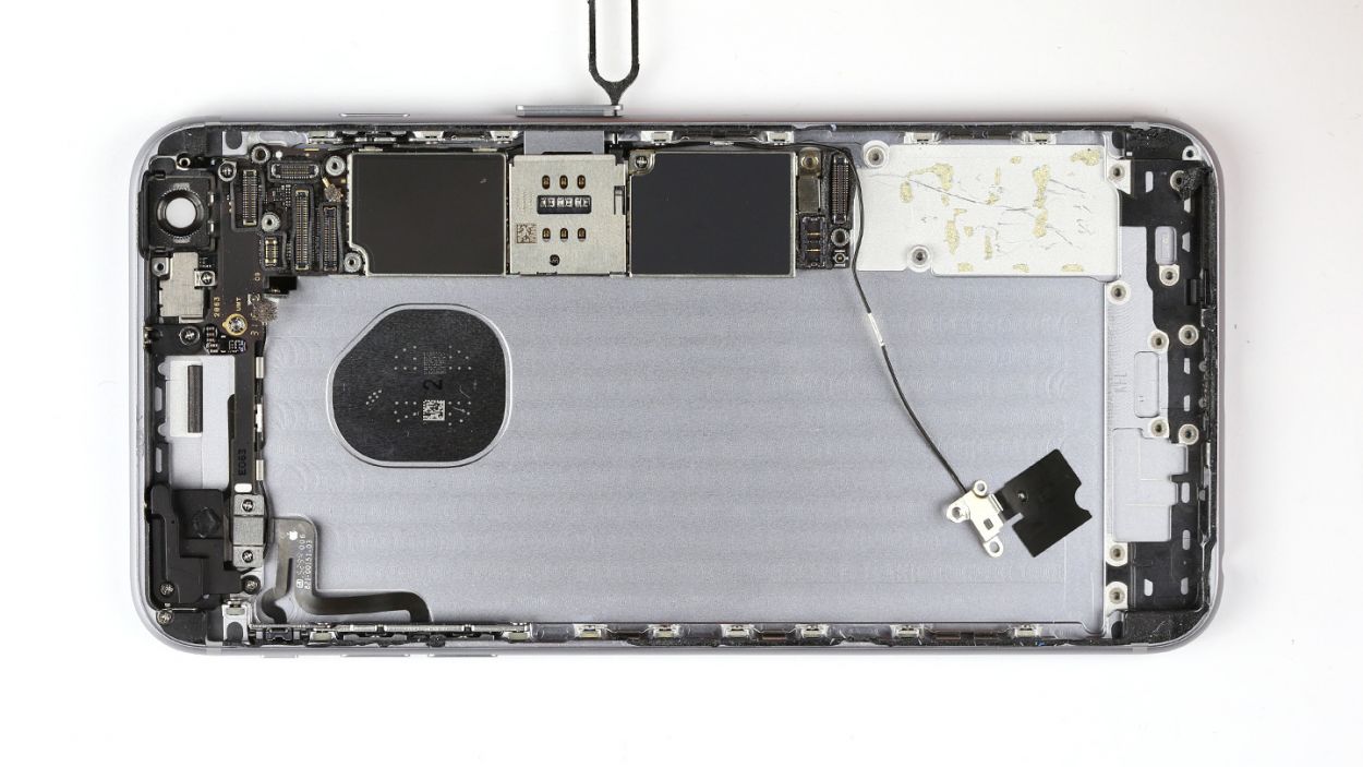
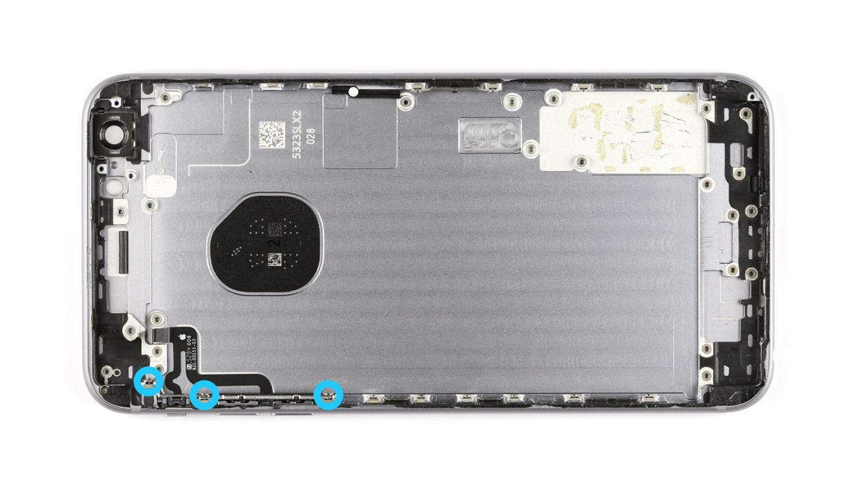
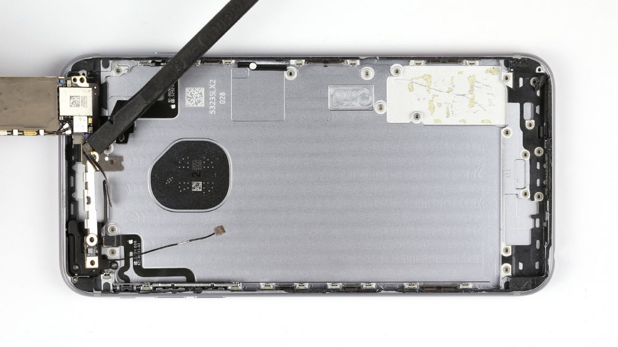
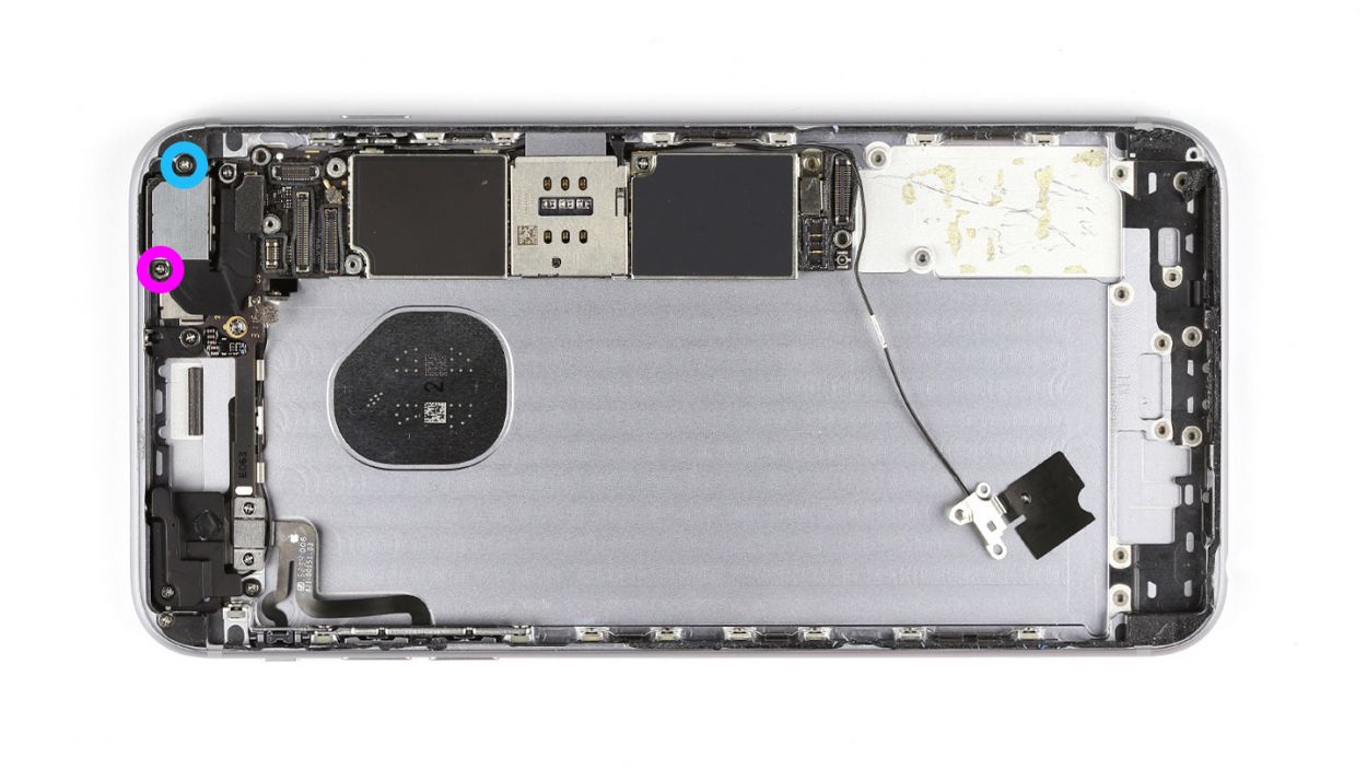
Step 14

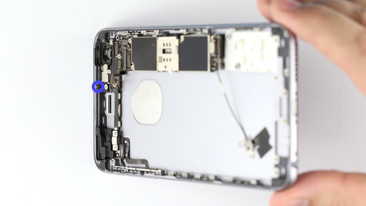


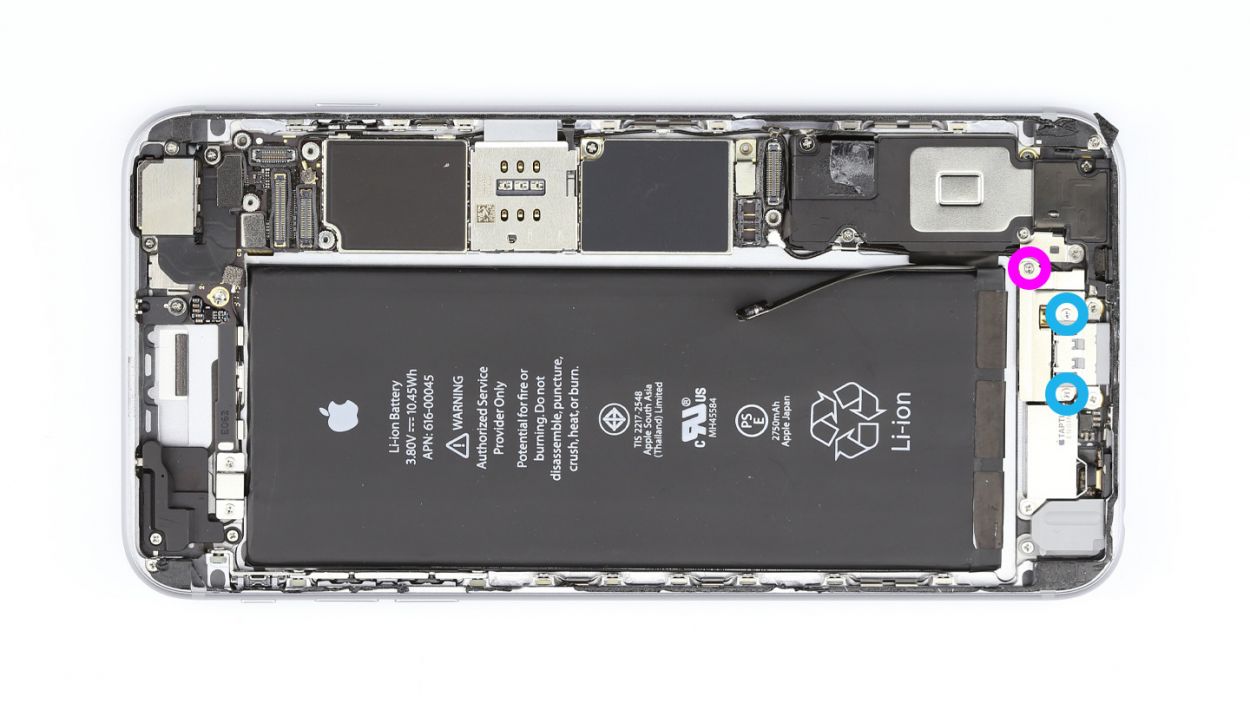
– Unplug the two antenna cables and detach the flexible flat standby cable’s connector. You’re almost there!
– Next, let’s tackle those seven screws keeping the logic board snug. Here’s the lineup: 1 x 1.4 mm Phillips screw, 1 x 1.8 mm flathead screw, 1 x 2.0 mm Phillips screw, 1 x 2.5 mm Phillips screw, 1 x 1.1 mm Phillips screw, and 2 x 2.7 mm Phillips screws. Keep them safe, okay?
– Now, gently take off the angled plate and keep it with those screws. You’re doing great!
– Remove the plate from the flexible flat volume cable’s connector and set it aside with the screws. Keep up the awesome work!
– Finally, disconnect the flexible flat volume cable’s connector from the logic board. You’re on the home stretch!
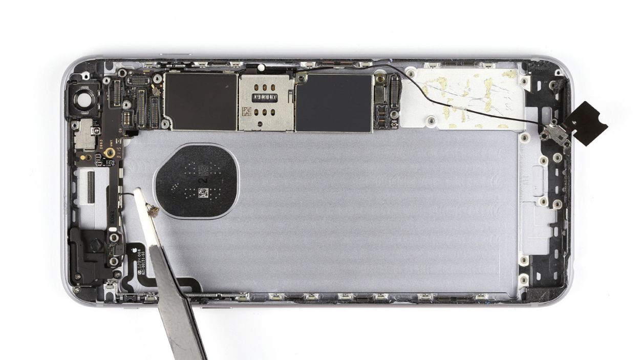
Step 15
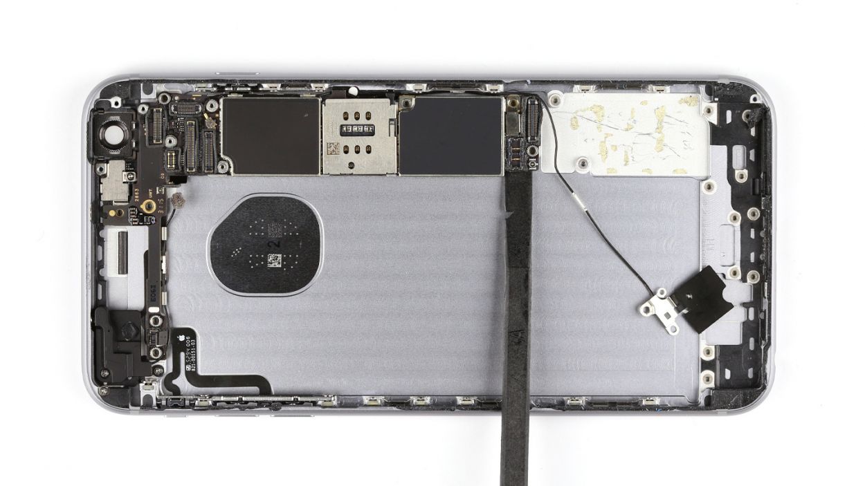


– Start by using the flat end of your spudger to gently unplug the logic board. You’ve got this!
– Next, let’s untangle those antenna cables from the logic board. They’re held tight at a few spots, so take your time.
– Now, carefully lift the logic board out of the back cover by angling it towards the shorter side. You’re almost there!
– Don’t forget, the bottom of the logic board is connected to the Wi-Fi antenna. Disconnect that connection and remove the logic board completely. Keep up the good work!
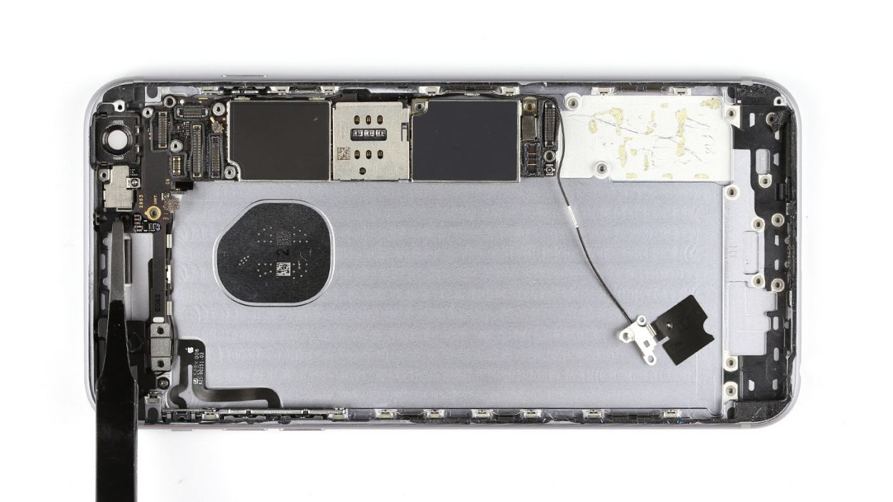
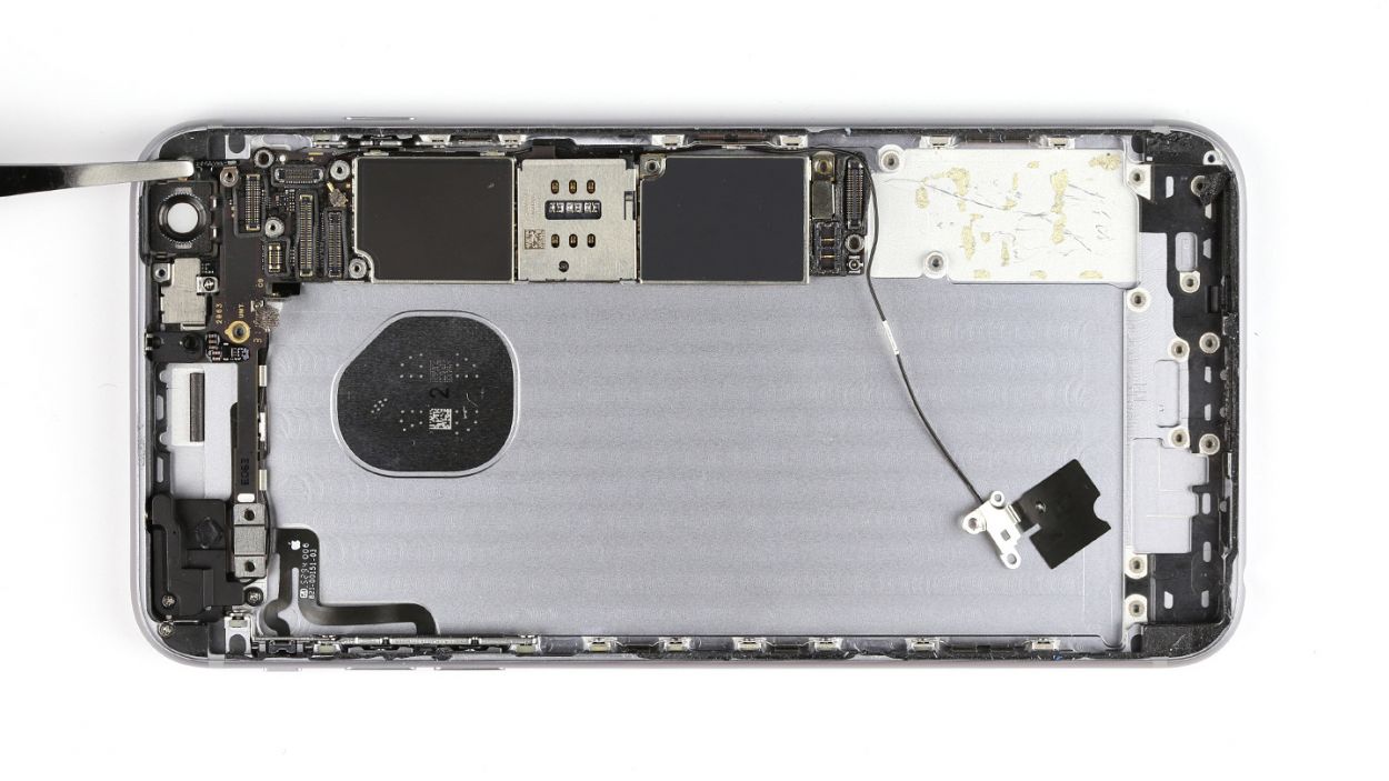
Step 16


– Let’s kick things off by removing those four Phillips screws—1 x 1.1 mm Phillips screw and 3 x 2.0 mm Phillips screws. Easy peasy!
– Next, lift out the plate that’s holding the ambient microphone and flash snugly in place. Don’t forget to keep it with the screws; they’re a team!
– Now, grab your trusty steel spatula and gently detach the standby/ambient microphone/flash cable from the back cover. A little hot air from a heat gun can make this step a breeze. Just slide the spatula under the cable at different points until it’s free as a bird!
– Finally, lift that cable out of the back cover and you’re one step closer to your goal!
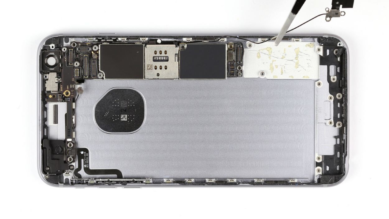
Step 17


– Grab those tweezers and gently peel away the sticker from the cover hiding that 1.6 mm Phillips screw.
– Time to unscrew! Remove the three Phillips screws: 1 x 1.6 mm, 1 x 2.6 mm, and 1 x 1.1 mm. Keep them safe!
– Carefully lift off the cover and keep it together with the screws—teamwork makes the dream work!
– Next, take out the screw securing the antenna—it’s a 1 x 1.2 mm Phillips screw.
– With your trusty tweezers, remove the Wi-Fi antenna like a pro!
Step 18

– Grab your trusty steel spatula and gently wiggle that volume control cable free. You’ve got this!
– Next, it’s time to unscrew those three little troublemakers. We’re talking about 3 x 2.2 mm Phillips screws, so keep your eyes peeled!
– Finally, go ahead and remove that volume control cable. You’re on a roll!
Step 19
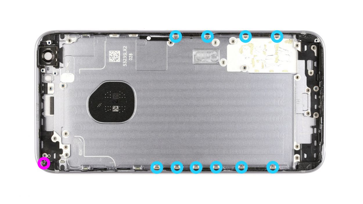

– Alright! Each of those five retaining brackets is held in place by a duo of Phillips screws. Go ahead and unscrew them! Toss those screws and brackets into the same container to keep them cozy together. That’s 10 x 1.6 mm Phillips screws we’re talking about!
– There’s a bonus bracket hanging out, secured by just one screw. Remove that screw and make sure to keep the bracket and screw together in your container. That’s 1 x 1.8 mm Phillips screw!
– Don’t forget to gather up all those little parts that aren’t already snuggled into the new back cover. You’re almost there!
Step 20


– Let’s get that volume control cable snugly into the back cover! Just make sure those buttons are lined up just right.
– Now, it’s time to secure everything with three screws. We’re talking about 3 x 2.2 mm Phillips screws—let’s fasten them down!
Step 21


– First up, let’s find that Wi-Fi antenna and place it nicely in the back cover!
– Now, grab that tiny 1 x 1.2 mm Phillips screw and fasten the antenna in place—you’re doing great!
– Next, let’s put the cover back on the antenna like a cozy blanket.
– Time to screw the cover onto the back cover! Use those 1 x 1.6 mm, 1 x 2.6 mm, and 1 x 1.1 mm Phillips screws. You’ve got this!
– Finally, don’t forget to cover that 1.6 mm screw with the sticker to keep everything neat and tidy!
Step 22


– First, let’s get that standby/ambient microphone/flash cable cozy in the back cover and stick it down nice and snug!
– Next up, pop the plate back on top of the ambient microphone and flash, like a protective little hat.
– Finally, secure everything in place with those four Phillips screws: 1 x 1.1 mm Phillips screw and 3 x 2.0 mm Phillips screws. You’ve got this!
Step 23

– First up, let’s connect the bottom of that logic board to the Wi-Fi antenna. It’s like a cozy hug for your tech!
– Next, gently nestle the logic board into the back cover. Just make sure you’ve got enough room for the next step—no one likes a cramped workspace!
– Finally, attach that antenna cable to the logic board. You’re doing awesome!
Step 24


– Let’s get that logic board connected to the flexible flat volume cable and pop that plate back on like a pro!
– Now, carefully position that angled plate back on the logic board, just like it was before.
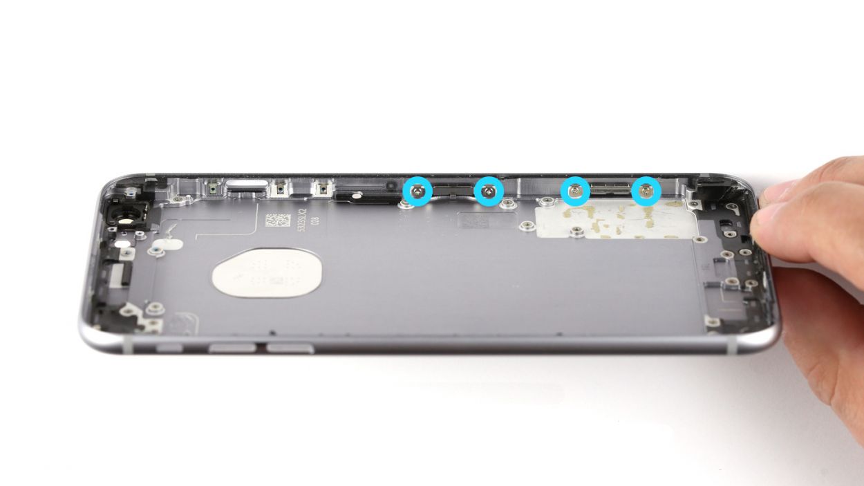
– Time to secure everything! Use those seven screws to fasten the logic board to the back cover. Here’s what you need: 1 x 1.4 mm Phillips screw, 1 x 1.8 mm flathead screw, 1 x 2.0 mm Phillips screw, 1 x 2.5 mm Phillips screw, 1 x 1.1 mm Phillips screw, and 2 x 2.7 mm Phillips screws. You’ve got this!
– Don’t forget to connect the two antenna cables and the flexible flat standby cable’s connector to the logic board. Almost there!
Step 25

Step 26


– Let’s put that camera back where it belongs!
– Next, grab the camera cover and screw it into place. If it’s still attached to the camera, no worries!
– Now, connect the camera’s cable and you’re all set!
Step 27


– First up, let’s peel off that big blue backing from the adhesive strips. It’s like unwrapping a gift!
– Now, stick those adhesive strips to the back of your battery and give them a good press to make sure they’re snug.
– And don’t forget to pull off that red protective film. You’re almost there!
Step 28


– Place the battery snugly in your iPhone. Just a heads-up, the battery will start to stick the moment those adhesive strips meet the back cover!
– Peel off that blue protective film from the ends of the adhesive strips. It’s like unwrapping a little surprise!
– Fold the ends of those adhesive strips over and secure them to the battery. You’re almost there!
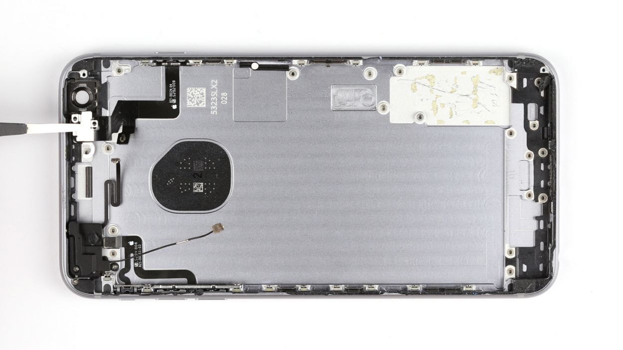
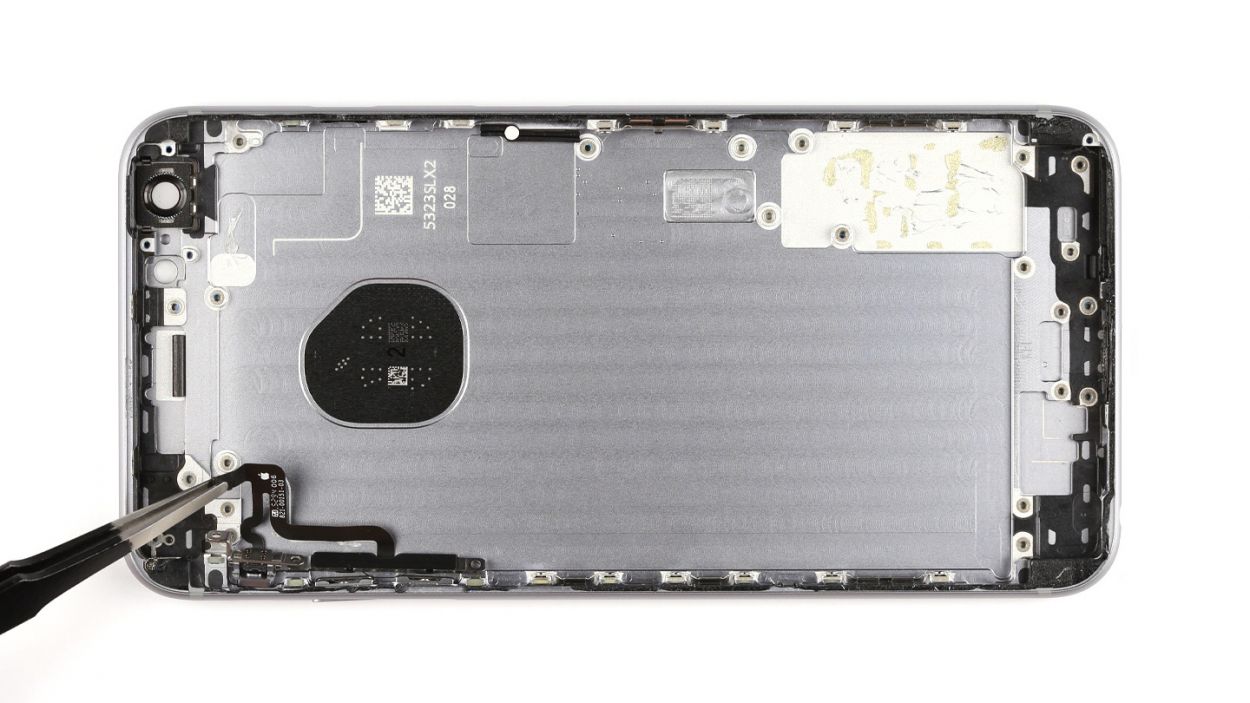
Step 29


1 × Antenna connection
Reuse that trusty old antenna cable and connect it to the lightning connector’s flex cable (check out the image for guidance). Just give it a gentle snap into its socket!
– Reposition the Lightning connector back to where it belongs, like a puzzle piece finding its home!
– Give that flexible flat cable a good press to ensure it sticks like it means it!
– Double-check that the two shiny gold microphones, the Lightning connector, and the headphone jack are snugly fitted into the frame. We want everything to be just right!
Step 30
– Let’s get that Lightning connector all snug and secure with four Phillips screws! Here’s what you’ll need: 1 x 3.0 mm Phillips screw, 1 x 1.1 mm Phillips screw (the angled one), 1 x 1.8 mm Phillips screw, and 1 x 1.3 mm Phillips screw. You’ve got this!
Step 31


– First, let’s get that speaker cozy in the back cover of your iPhone 6s Plus. Just make sure those antenna cables are nestled nicely in their guides!
– Now, give that antenna a little hug and stick it to the speaker.
– Use the guide to gently clamp the antenna cable against the speaker—teamwork makes the dream work!
– Finally, secure the speaker with those seven Phillips screws. Here’s the lineup: 2 x 2.2 mm Phillips screws with large heads, 2 x 2.6 mm Phillips screws, 2 x 1.5 mm Phillips screws, and 1 x 2.4 mm Phillips screw (the angled one!). You’ve got this!
Step 32

– Place the Taptic Engine back where it belongs, like a puzzle piece fitting in perfectly!
– Secure the Taptic Engine using those two screws: one is a 2.1 mm Phillips screw, and the other is a 3.0 mm Phillips screw. You’ve got this!
– Connect the contact to the flexible flat Lightning cable, and you’re on your way to success!
Step 33

– Alright, it’s time to put that plate back in its rightful place! Just gently set it down.
– Now, let’s secure that plate with three screws to keep everything snug and tidy: one 2.6 mm Phillips screw and two 3.3 mm Phillips screws. You’re doing great!
Step 34


– Reconnect those connectors! Sometimes it takes a couple of tries to get that display connector just right. Handle it with care to avoid any bending—especially the Touch ID cable, front camera/sensor/earpiece/ambient microphone, and the display.
– Once everything is snug, power up your iPhone! Check that LCD, touchscreen, proximity sensor, front camera, and earpiece are all working like champs. If those display connectors are feeling a bit off, you might see some funky stripes or notice parts of the touchscreen acting up.
– Now, let’s put the cover back on and secure it with the screws: 1 x 2.6 mm Phillips screw, 3 x 1.2 mm Phillips screws, and 1 x 1.6 mm Phillips screw. You’re doing awesome!
If those display connectors are feeling a bit shy and not snugly connected, you might see some funky stripes on the screen or find parts of your touchscreen playing hard to get. Let’s make sure everything’s hooked up right!
Step 35

– Alright, let’s get everything back in its cozy spots! First, reconnect the antenna, Lightning connector, battery, and logic board. You’re doing great!
– Now, it’s time to put that silver cover back on—like tucking in a blanket!
– Finish it off by securing the cover onto the logic board with a couple of screws: 1 x 2.0 mm Phillips screw and 1 x 2.9 mm Phillips screw. You’ve got this!
Step 36
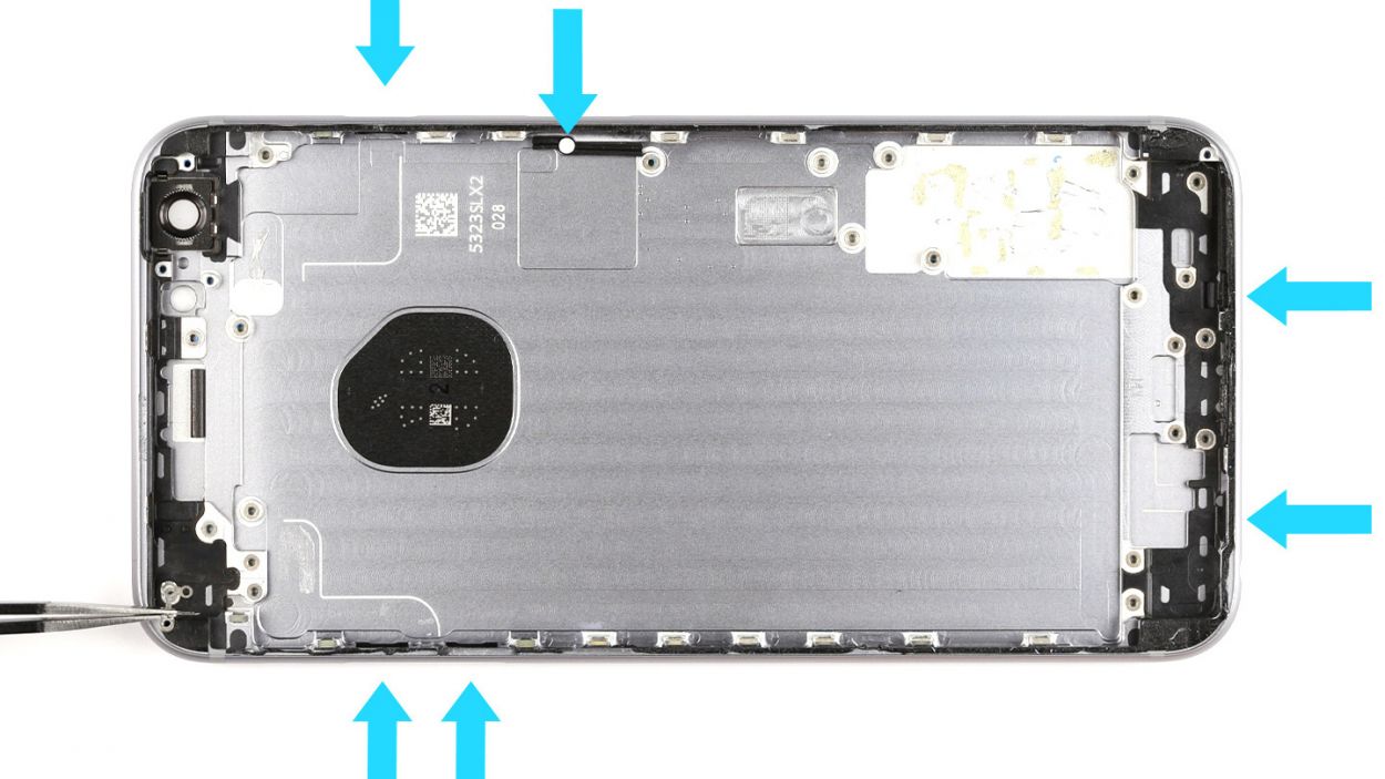
– Now, let’s gently lower that display back down. Make sure it clicks into place at the top edge where those connection cables hang out—it’s like a little hug for your phone!
– Give the display a gentle push towards the Home button until it’s snug in the frame. We want it to sit perfectly flush with the frame, just like it was meant to be!
Step 37
– Now, let’s get those two pentalobe screws back in at the bottom of the enclosure! Just a reminder, we’re talking about 2 x 3.3 mm pentalobe screws here—let’s make sure they feel right at home!
Step 38

Heads up! When you pop that battery out, your iPhone might forget the time and default to 1:00 a.m. on 1/1/1970. If that happens, you might run into some hiccups connecting to the cellular network. So, let’s get that time sorted!
– Let’s sync your iPhone with iTunes or hop onto a WLAN network and hang tight until the time gets set up right!
– Pop out the SIM tray, give that SIM card a little love, and then slide it back in.
– Turn on airplane mode for a moment and then switch it back off. You’re doing awesome!