DIY Guide: How to Replace MacBook Pro 15 Upper Case Anti Glare – Step-by-Step Tutorial
Duration: 45 minutes
Steps: 37 Steps
Hey there! Friendly reminder: Before you dive in, double-check that you’ve got all your tools ready. If you need help, you can always schedule a repair. Let’s get started and make this repair smooth and fun!
Follow this guide to swap out the upper case on those Anti-Glare Models. If you need help, you can always schedule a repair!
Step 1

– Time to get your screwdriver ready! Unscrew those ten little screws that are holding the lower case snugly against the upper case. Let’s get this party started!
Step 2

– Get a grip on both sides of the lower case near the vent and give it a good lift to pop it off those two clips holding it to the upper case.
– Lift the lower case off and set it aside.
Step 3

Don’t have a Pentalobe driver? No worries! You can totally use a 1.5mm flathead screwdriver as a quick fix. Just make sure it fits snugly across two of the five points on the screw head before trying to loosen the screw. A loose fit could easily strip the screw head, and nobody wants that!
If your screwdriver head feels too loose, just grab a bigger bit and file it down until it fits snugly. Then you’re good to go!
You don’t absolutely have to follow steps 3-7 to remove the battery when replacing the hard drive, but it’s a good idea to disconnect all power sources before tinkering with electronics.
– Three Pentalobe screws hold the battery in place. Use this special driver to take them out.

Step 5

– Grab your spudger and gently lift the tab of the ‘Warning: Do not remove the battery’ sticker while you unscrew the five-point Pentalobe screw hiding underneath. If you need help, you can always schedule a repair.
Tools Used


Step 7

– Gently tilt the battery back just enough to reach that sneaky battery cable connector.
– Carefully pull the battery cable connector away from its cozy spot on the logic board and lift the battery out of the upper case.
Step 8


– Gently slide the flat end of a spudger under the fan cable connector and lift it up from its cozy spot on the logic board. You’ve got this!
Check out the second and third pictures to spot the fan socket and connector! Just a heads up: when you’re using your spudger to gently lift the fan connector straight out, be super careful not to snap that plastic fan socket off the logic board. The layout in the second picture might look a bit different from your device, but don’t worry—the fan socket is still the same. If you need help, you can always schedule a repair!
To unhook the connector, give the spudger a little twist from underneath the fan cable wires. If you need help, you can always schedule a repair.
Tools Used
Step 9

– Ready to bid farewell to those three sneaky T6 Torx screws holding the fan captive? Let’s give them their freedom by unscrewing them from the upper case.

Step 11

Apple cleverly sticks a little strip of clear plastic with adhesive on one side to the logic board behind the camera cable connector, keeping it snug in its spot. Just a friendly reminder: when you’re moving it aside, be super careful not to knock off any tiny surface-mount components from the logic board. You’ve got this!
– Gently hold down one end of the cable retainer with a finger, then use a spudger’s tip to lift and turn the other end away from the camera cable connector.
Tools Used
Step 12

Gently slide the connector sideways along the logic board, not upward.
– Gently pull the camera cable straight out from its socket to disconnect it. If you need help, you can always schedule a repair.
Step 13

– Get your spudger and with the flat end, gently lift the optical drive cable connector off the logic board.
Tools Used
Step 14

– Grab your trusty spudger and gently lift the subwoofer connector straight up from the logic board. You’ve got this!
Tools Used
Step 15

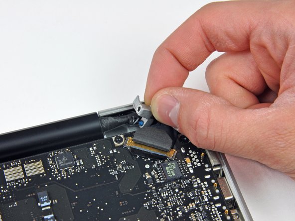
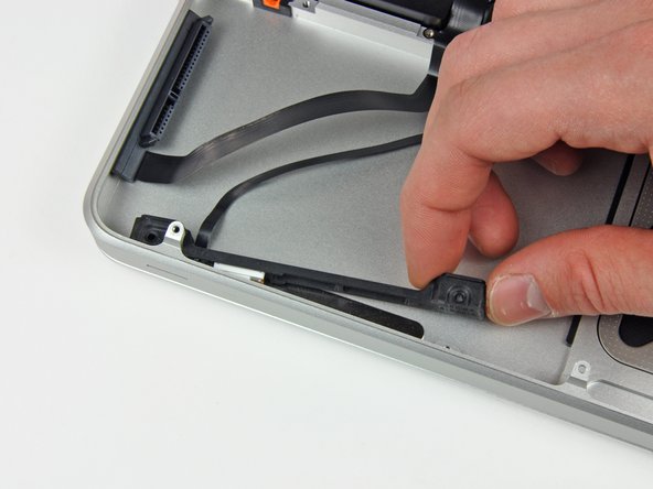
– Gently slide the flat end of a spudger under the hard drive/IR sensor cable connector and lift it off the logic board with care. You’ve got this!
Tools Used
Step 16


– Get rid of those two tiny 1.5 mm Phillips screws that are keeping the cable cover attached to the logic board.
– Lift that cable cover gently out of the upper case.
Step 17

– Grab your trusty spudger and gently lift the trackpad flex ribbon cable connector away from the logic board. You’ve got this!
Tools Used
Step 18

– Grab your trusty spudger and gently lift the flap that holds the keyboard ribbon cable in place.
– Carefully pull the keyboard ribbon cable straight out of its socket, like you’re unwrapping a surprise!
Tools Used
Step 19

– Get your trusty spudger and delicately lift the battery indicator ribbon cable connector off the logic board.
Tools Used
Step 20

– First up, grab your trusty screwdriver and take out that lone 7 mm Phillips screw holding the display data cable retainer snugly to the upper case. You’ve got this!
– Now, gently lift that display data cable retainer off the upper case and set it aside. You’re making great progress!
Step 21


Make sure to pull the connector parallel to the face of the logic board, not straight up from its socket. If you need help, you can always schedule a repair.
Step 22


– With the tip of a spudger, gently lift the flap holding the keyboard backlight ribbon cable.
– Slide the keyboard backlight ribbon cable straight out from its slot.
Tools Used
Step 23

Hold up! Don’t yank the logic board just yet—there are some sneaky connectors attached to the bottom that need to be unplugged first. If you need help, you can always schedule a repair.
– Take out these screws:
Step 24

Hold up! Don’t take out the logic board just yet!
Make sure the logic board is completely disconnected from the upper case, except for the battery connector, before moving forward.
– Gently lift the logic board assembly from the left side and work it out of the upper case, watching the port side that might get stuck during removal. If you need help, you can always schedule a repair.
Step 25


– Gently lift the logic board to create some room and grab a spudger to pop the microphone up from the upper case.
– Shift the logic board away from the port openings and raise the whole thing out of the upper case.
– To make your life easier when putting back the logic board, simply press the microphone into its spot near the left speaker so it stays put.
Tools Used
Step 26

These screws are snugly fastened to the hard drive bracket. If you need help, you can always schedule a repair
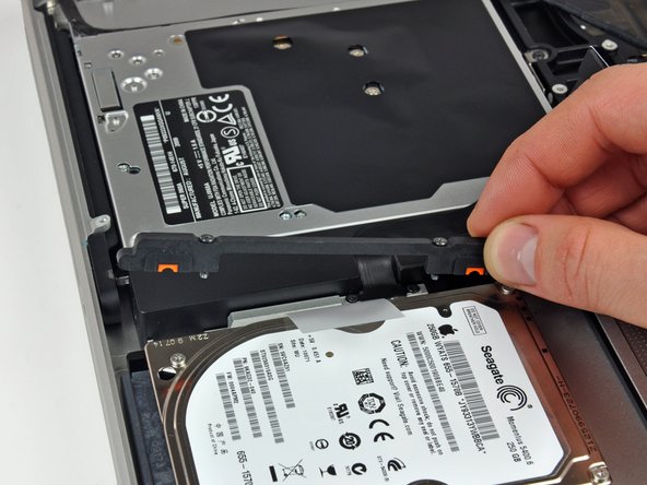
– Unscrew those two Phillips screws holding the hard drive bracket in place on the upper case. You’ve got this!
– Gently lift the hard drive bracket away from the upper case. Easy peasy!
Step 27

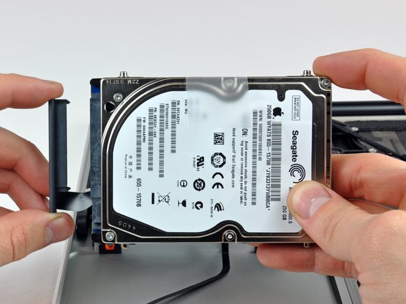
– Gently lift the hard drive out of the upper case by its plastic pull tab while being mindful of the cable attaching it to the computer. If you need help, you can always schedule a repair.
Step 28

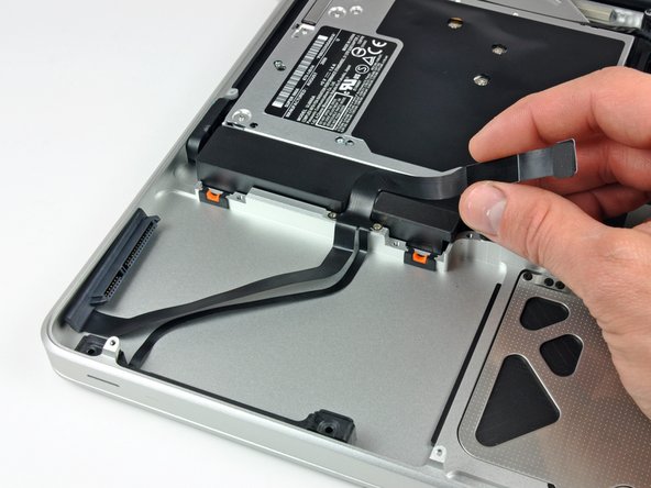
– Gently detach the hard drive from its cable by sliding the cable connector away from the drive.
Step 29

– Pop out these four screws holding the hard drive and IR sensor cable to the upper case:
– Shift the hard drive and IR sensor bracket away from the case edge.
– Gently lift the hard drive and IR sensor cable from the upper case.
– Take out the hard drive/IR sensor cable from the upper case and place it aside.
Step 30
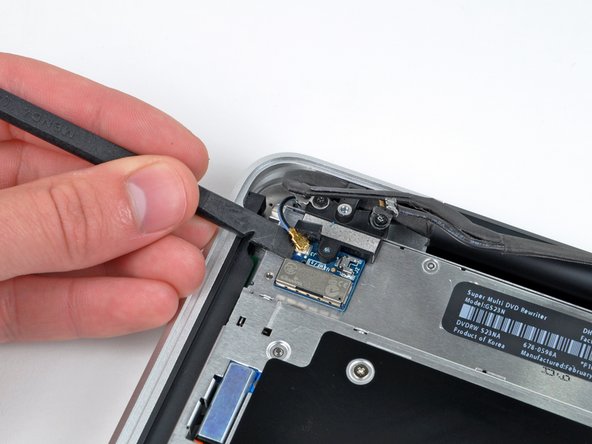

Gently slide the connector out parallel to the logic board’s surface—no need to pull it straight up!
– Give that Bluetooth cable a gentle tug to disconnect it—just pull the male end straight out of its cozy little socket.
– Now, grab your trusty spudger and use its flat end to carefully coax the AirPort antenna off its snug spot on the AirPort card. Easy peasy!
Tools Used
Step 31
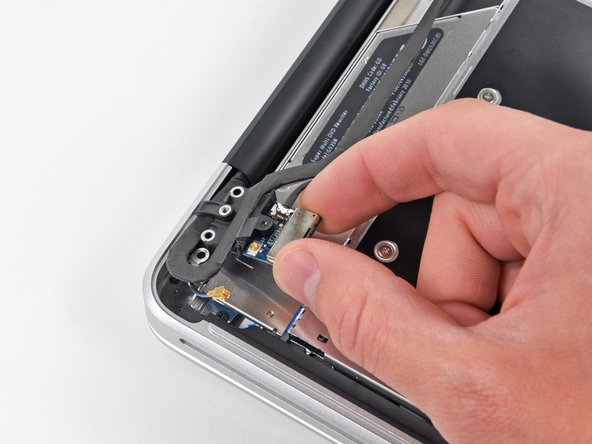

One of the screws might get a bit too cozy in the Bluetooth/camera cable ground loop. If you’re swapping out the display, don’t forget to give this little guy a ride to the new unit.
– Take out those two 8 mm Phillips screws holding the Bluetooth/camera cable retainer in place in the upper case.
– Carefully lift the AirPort board/cable retainer assembly out of the upper case. Need a hand? You can always schedule a repair.
Step 32

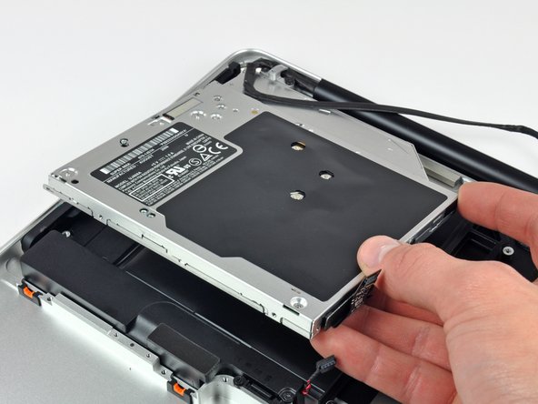
– Remove the three 3.5 mm Phillips screws securing the optical drive to the upper case.
– Lift the optical drive from the left side and gently pull it out of the computer. If you need help, you can always schedule a repair
Step 33

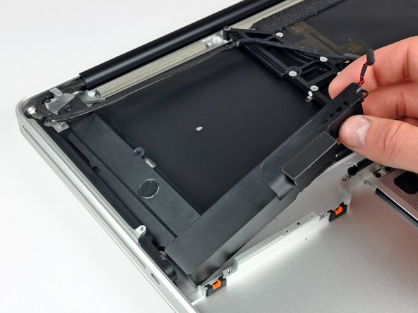
– Let’s start by removing the four screws holding down the subwoofer and right speaker to the upper case.
– Now, gently lift the subwoofer and right speaker assembly out of the upper case. If you need help, you can always schedule a repair.
Step 34
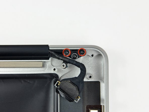

We’re keeping one screw snugly in each hinge to make the next steps a breeze.
– Unscrew those two outer 6 mm Torx screws on each side of the display holding it to the upper case—yep, that’s four screws in total. You’ve got this!
Step 35

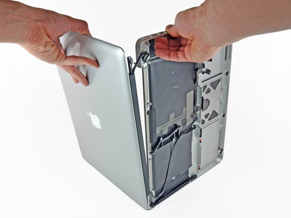
– Start by opening up your MacBook Pro until the display is standing tall and proud, forming a perfect right angle with the upper case.
– Next, lay your open MacBook Pro on a flat surface, just like in the picture. We want it to be comfy while we work!
– Now, give a gentle grip to the display and upper case with one hand, while with your other hand, carefully remove the 6 mm Torx screw from the lower display bracket. You’ve got this!

Step 37

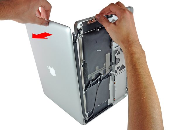
– Grab the upper case with your right hand and give it a slight twist towards the top of the display so the upper display bracket clears the edge of the upper case.
– Rotate the display slightly away from the upper case.
– Lift the display away from the upper case, watching out for any brackets or cables that might get caught. If you need help, you can always schedule a repair.


