DIY Guide: How to Replace the LCD on Nintendo Switch
Duration: 45 minutes
Steps: 51 Steps
Get ready to tackle that pesky LCD panel replacement on your Nintendo Switch! This guide is all about swapping out the damaged or faulty LCD panel. If you’re looking to replace both the LCD panel and the digitizer together, check out our screen replacement guide. The Switch is equipped with JIS screws, but don’t worry if you only have a Phillips screwdriver handy—it’ll work in a pinch! Just be gentle with those screws; we don’t want any stripping happening here. Our Phillips bits are designed to work seamlessly with JIS-style screws. Quick tip: If your display glass is cracked or shattered but the screen still functions, you’ll need to replace the digitizer instead. Also, when you take off the shield plate, remember to replace the thermal compound between the plate and the heatsink. Regular thermal paste isn’t meant for big gaps, so grab some K5 Pro viscous thermal paste for that. You’ll also need standard thermal paste for the CPU. While you can complete this repair without removing the heat sink and game card reader, it does make disconnecting and reconnecting the LCD panel ribbon cable a bit trickier. Keep that in mind as you dive into this repair! Just a heads up: this guide, along with the part we offer, is compatible with both the original Nintendo Switch model from 2017 and the refreshed model from 2019 (model numbers HAC-001 and HAC-001(-01), respectively). If you need help, you can always schedule a repair.
Step 1


Before diving into this repair, be sure your device is totally powered down.
– Give that little round button on the back of your Joy Con controller a firm press and hold it down like it’s the last cookie in the jar.
– While you’re keeping that button down, smoothly slide the controller upward, like you’re raising the roof!
Step 2


Now it’s time to get the other Joy Con in on the action – just repeat the same steps you just followed!
– Keep sliding that Joy Con upwards until it’s totally detached from the console. You’re making great progress!
Step 3

As you work through this repair, keep track of each screw and make sure it returns to its original spot.
– Grab your trusty Y00 screwdriver and let’s tackle those four 6.3 mm-long screws holding the rear panel in place. You’ve got this!
Step 4


To keep those stubborn screws from stripping, press down firmly, take your time, and if they still won’t budge, give a JIS 000 or PH 000 driver a whirl!
– Grab your trusty JIS 000 driver or a PH 000 driver and get ready to unscrew these little guys holding the rear panel in place:
– One 2.5 mm screw up top on the device’s edge.
– Two 2.5 mm screws chilling at the bottom edge of the device.
Step 5


– Grab a JIS 000 screwdriver or a PH 000 driver and loosen up those two 3.8 mm screws chilling on each side of your device. One per side—easy peasy!
Step 6


Before diving into the next step, make sure to pop out that microSD card from its cozy little slot. Let’s keep things smooth sailing!
– Give the kickstand a gentle flick with your finger to pop it open—it’s like opening a secret hatch to cool tech.
Step 7

– Grab your trusty JIS 000 screwdriver or the official iFixit PH 000 driver and gently unscrew that 1.6 mm screw hiding in the kickstand well.
– Now, go ahead and close the kickstand.
Step 8


The game card cartridge flap hooks onto the other half of the plastic shell, keeping the rear panel from lifting off completely if it’s still closed.
– Flip open the game card flap like you’re opening a treasure chest.
– Gently lift the rear panel from the bottom of the device—it’s like peeling off a protective layer. Take it slow and steady!
Step 9

– Grab your trusty JIS 000 screwdriver or the official iFixit PH 000 driver and gently unscrew the 3.1 mm screw that’s holding the microSD card reader in place. You’ve got this!
Step 10


– Time to get a little gentle and a lot careful! Use your fingers or a trusty pair of tweezers to carefully lift the microSD card reader straight up and out of the device. Easy does it!
– When you’re putting everything back together, make sure the press connector under the foam pad is securely connected to the motherboard. Pro tip: removing the foam pad before reinstalling the card reader can make things a lot easier. If you need a little extra help, don’t worry! You’re doing great.
Tools Used

Step 11

– Grab your JIS 000 screwdriver or an official Salvation Repair PH 000 driver and unscrew the six 3 mm screws holding the shield plate. Easy peasy!
Step 12


Take your time peeling the foam—if it’s being stubborn, don’t muscle it! Try gently working from different angles to coax it off without causing any rips.
– Grab your fingers or some trusty tweezers and gently lift up the foam piece sitting at the top edge of the device, right by the fan exhaust port. Easy does it!
Tools Used
Step 13


A thick, pink thermal paste connects the shield plate to the copper heat sink beneath. This keeps your Switch cool as a cucumber.
If you feel some resistance, don’t worry! It’s just the shield plate being a little clingy with the heat sink, thanks to the thermal paste.
– Slide a spudger under the shield plate along the device’s edge.
– Pop up the shield plate and take it off the device.
– Careful now! You can reuse that pink thermal compound—just keep it clean and ensure it stays snug between the heat sink and the shield during reassembly.
– Need to swap it out? Check out our thermal paste guide to ditch the old compound and replace it with something like K5 Pro during reassembly.
Tools Used


Step 14


– Grab a spudger and gently pop the battery connector straight up out of its snug little spot on the motherboard. Easy does it!
Tools Used
Step 15

– Grab your trusty JIS 000 screwdriver or the official PH 000 driver from iFixit and let’s get those three 3 mm screws outta there! They’re holding the heat sink tight to the motherboard, and we need to free it up. You’ve got this!
Step 16
The foam is fragile and can rip easily. Use this technique to gently peel it off:
The foam only needs to be peeled back enough to clear the fan.
– Gently peel away the two foam pieces that are cozying up to both the heatsink and the fan.
– Slide the tip of a spudger underneath the part of the foam that’s not making friends with anything.
– Use your finger to press down on the top of the foam, keeping it steady.
– Roll the spudger tip all the way to the other end of the foam to set it free.
Tools Used
Step 17


You might feel a bit of resistance, and that’s totally normal—it’s just the heat sink being slightly glued to the CPU with thermal paste.
– Time to get that heatsink off! Use a spudger or your fingers to carefully lift it up and away from the motherboard.
– Now it’s time for some cleaning! Grab some high-concentration isopropyl alcohol (90% or higher) and a microfiber cloth, and gently wipe away the old thermal paste from the heat sink and CPU. Before putting everything back together, apply some fresh thermal paste to the CPU.
– Thermal paste time! Make sure to apply it to all the surfaces that had it before, including the area between the heatpipe and aluminum shield – that’s where the Switch gets some extra cooling help.
Tools Used

Step 18


– Grab an opening tool or use your fingernail to gently pop up the small, hinged locking flap on the digitizer cable’s ZIF connector.
Step 19


No need to get frustrated! If the cable isn’t going in, just check that the locking flap is open, adjust the cable, and give it another shot.
If your touchscreen is being stubborn after the repair, but your Game Card reader is working just fine, double-check that this cable is properly plugged in. If neither is working, no worries! Just head to the next step to investigate the Game Card connector.
– Grab a trusty pair of tweezers and carefully slide that digitizer cable right out of its cozy connector on the game card reader board.
– Before you pop the cable back in during reassembly, make sure that ZIF connector locking flap is standing tall and flipped up.
– With the cable lined up parallel to the board, gently ease it into its connector like a pro.
Tools Used
Step 20


If your touch screen is playing hard to get or those game cards are MIA after putting everything back together, it might be because this press connector isn’t fully reconnected. Go ahead and gently disconnect it, then give it another shot!
– Grab your trusty spudger and gently lift the headphone jack and game card reader connector straight up to disconnect it from the motherboard. Easy peasy!
– When it’s time to reconnect, simply align the connectors carefully and press down on one side until you hear that satisfying click, then do the same on the other side. Avoid pressing down in the middle—nobody likes a bent pin! If things aren’t lining up right, take a moment to realign before going any further. Remember, if you find yourself in a jam, you can always schedule a repair.
Tools Used
Step 21

– Grab a JIS 000 screwdriver or an official PH 000 driver from your toolkit and get ready to tackle those three 3.1 mm screws holding the headphone jack and game card reader board in place. Let’s get this done!
Step 22


– Grab your tweezers or just use your fingers and carefully pop off the headphone jack bracket. Easy peasy!
Tools Used
Step 23


– Time to get a little hands-on! Use a pair of tweezers or your fingers to carefully remove the headphone jack and game card reader board. It’s like a little puzzle, and you’re the master puzzle-solver!
Tools Used
Step 24


– Grab a trusty opening tool, spudger, or even your fingernail, and gently flip up the tiny, hinged locking flap on that LCD ribbon cable ZIF connector.
Tools Used
Step 25


– Grab a pair of tweezers and gently slide the ribbon cable out of its connector on the motherboard—easy does it!
Tools Used
Step 26


– Grab an opening tool, spudger, or just your fingernail and gently lift up the small, hinged locking flap on the smaller LCD ribbon cable ZIF connector.
Tools Used
Step 27


– Grab your tweezers and carefully slide the ribbon cable out of its connector on the motherboard. Easy does it!
Tools Used
Step 28

You can use a hair dryer, heat gun, or hot plate, but remember to keep it cool! Overheating can be a real bummer for your device, especially the display and internal battery, which are both sensitive to heat. So, let’s keep things chill while we work our magic!
– Warm up an iOpener and place it on the bottom edge of the screen for about two minutes to help loosen that stubborn adhesive.
Tools Used

Step 29


Older devices can be a bit stubborn, so don’t sweat it if it’s tricky. Add some extra heat, take a deep breath, and give it another go.
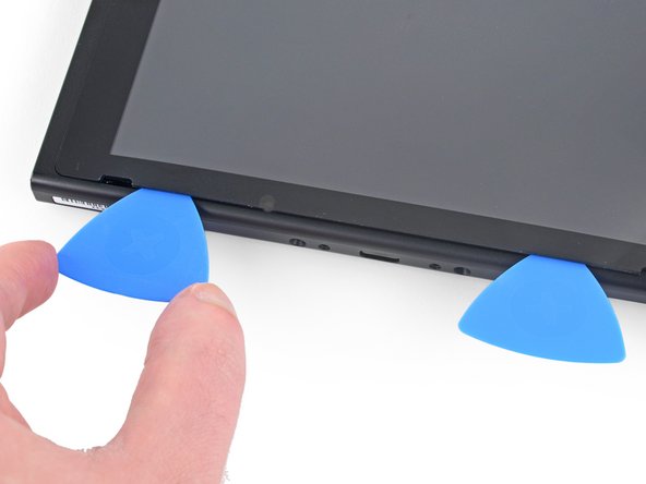
– Grab a suction cup and stick it on the bottom-left corner of your screen.
– Give that suction cup a good pull with steady strength to open up a little space.
– Carefully slide the tip of an opening pick into that gap, but only go in about 5 mm, alright?
Step 30


– Time to get this repair started! Slide the opening pick along the bottom edge of the screen to break through the adhesive – it’s like a special key to unlocking your device’s inner workings.
– Leave that pick right where it is, nestled in the screen’s edge, to prevent the adhesive from getting all clingy with the frame again.
Step 31
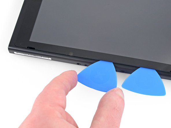

– Pop in another opening pick right next to the first one—teamwork makes the dream work!
– Now, glide that pick back toward the left side like you’re drawing a smooth line.
– Let that pick chill there for now.
Step 32

– Warm up the left edge of the screen for about two minutes to loosen up that sticky adhesive.
Step 33


– Keep gliding that opening pick around the bottom-left corner to cut through the adhesive.
Step 34


– Keep gliding that opening pick along the left edge of the screen to cut through the adhesive like a pro.
Step 35

– Warm up the top edge of the screen for about two minutes to loosen that stubborn adhesive.
Step 36


– Keep gliding that opening pick around the top-left corner of the screen—you’re slicing through that sticky adhesive like a pro!
Step 37


– Glide that opening pick along the top edge of the screen, slicing through the adhesive like a pro.
Step 38


– Warm up the right edge of the screen for about two minutes to loosen that stubborn adhesive.
– Gently slide the flat end of a spudger into the gap along the left edge of the screen.
– Carefully lift the left edge of the screen, opening it like a book. Take your time; you’ve got this!
Tools Used
Step 39


Be careful not to catch any of those delicate ribbon cables on the frame while you’re lifting off the screen. You’ve got this!
– Carefully lift the right side of the screen straight up and away from the device, guiding the ribbon cables gently through the frame as you go.
– If the adhesive is still tacky, feel free to reuse it. Otherwise, swap it out with some trusty double-sided tape, like Tesa tape.
Step 40
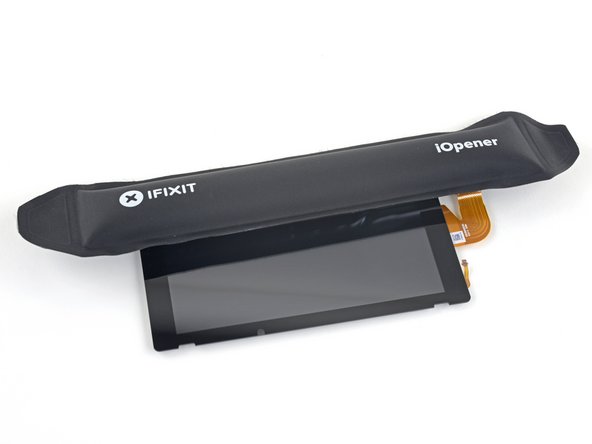
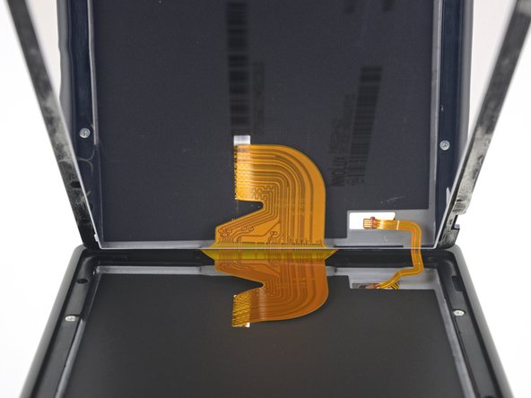
– Let’s get this repair started! Heat the top edge of the screen assembly for about two minutes to loosen the adhesive that’s keeping the LCD panel stuck to the digitizer. This will make the next steps a whole lot easier!
Step 41


No need to stress about how deep the opening pick goes—5 mm is more than enough to slice through that pesky adhesive.
You can gently flex the digitizer to make a wider gap, but don’t go too wild—bending it too far could damage it, especially if you plan on reusing it.
– Flip the screen assembly over like you’re turning the page of a book.
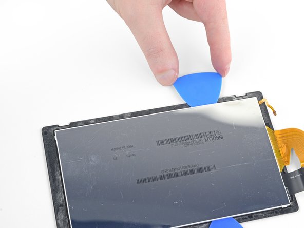
– Slip an opening pick between the LCD panel and the digitizer at the top-left corner—kind of like sliding a guitar pick into your favorite riff.
– Glide the opening pick along the top edge of the screen assembly to gently cut through the adhesive holding it all together.
Step 42


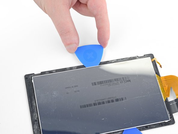
– Keep gliding that opening pick along the top edge of the screen to loosen up the adhesive—you’re almost there!
Step 43

– Warm up the left edge of the screen assembly for about two minutes to make that adhesive nice and pliable.
Step 44


– Now it’s time to get this repair started! Insert the opening pick into the left edge of the screen assembly and gently slide it along to break through the adhesive. This might take a little patience, but you’ve got this!
Step 45


– Keep gliding that opening pick around the bottom-left corner of the screen assembly to slice through the adhesive.
Step 46

– Warm up the bottom edge of the screen assembly for about two minutes to loosen up that adhesive. It’s like giving it a little spa treatment before you go in for the repair.
Step 47

– Keep gliding that opening pick along the bottom edge and slice through the adhesive like a pro.
Step 48

– Warm up the right edge of the screen assembly for about two minutes to loosen that adhesive and make your life a whole lot easier!
Step 49


– Take your trusty spudger and gently wedge the flat end between the LCD panel and the digitizer along the left side of the screen assembly.
– Now, with care and patience, lift the left side of the LCD panel slowly, like you’re opening up a new book. Nice and easy does it!
Tools Used
Step 50


The LCD ribbon cable might be a bit clingy with the digitizer. If it’s not budging easily, just warm that area up a bit more and give it another go!
– Keep on gently lifting that LCD panel away from the digitizer to successfully separate those two components! You’re doing great!
Step 51

If your shiny new LCD panel doesn’t come with its own sticky side, no worries! Just follow this guide to add some pre-cut adhesive around the edges before putting everything back together. You’ve got this!
– Take a moment to compare your shiny new replacement part with the original. You might need to swap over some components or peel off those pesky adhesive backings before you dive into the installation.
– When it’s time to put your device back together, just retrace your steps in reverse. Easy peasy!
– If your new LCD panel is acting a bit funky after powering up, no worries! Just power it down, disconnect the battery connector, and then reconnect it. Sometimes a little reset is all it needs.
– Got some e-waste? Make sure to drop it off at an R2 or e-Stewards certified recycler. Let’s keep our planet happy!
– If things didn’t go quite as planned, don’t sweat it! Try some basic troubleshooting, or feel free to reach out to our Nintendo Switch Answers community for a helping hand.
– And remember, if you ever find yourself in a jam, you can always schedule a repair.
Success!