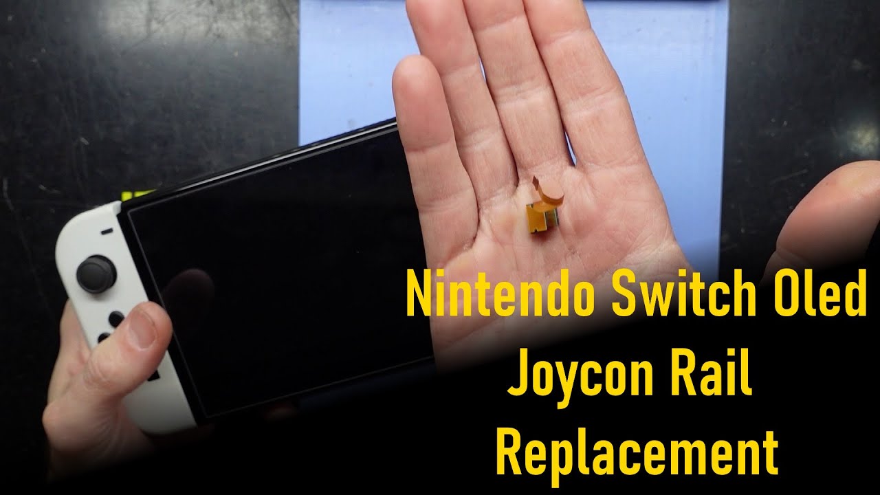
DIY Guide: How to Replace the Nintendo Switch OLED Sensor Rail
Duration: 45 minutes
Steps: 31 Steps
Before diving in, make sure your Switch’s battery is drained to less than 25%—safety first, my friend!
Ready to swap out the right Joy-Con sensor rail on your Nintendo Switch OLED? Let’s do this! First, for safety reasons, make sure your battery is at 25% or less before diving in. This helps minimize the risk of fire if the battery takes an accidental hit. If the battery looks swollen, handle it carefully and take the necessary precautions. The Switch OLED’s screws are JIS-style, but no worries—you can use a Phillips screwdriver if that’s what you’ve got handy. Just go slow and steady to avoid stripping the screws. Oh, and when you remove the shield plate, don’t forget to replace the thermal compound between it and the heatsink. Regular thermal paste won’t cut it for those larger gaps, so grab some K5 Pro viscous thermal paste to get the job done right. Let’s make this repair happen!
Step 1


Before diving into this repair adventure, ensure your device is totally powered down and ready for action.
– Find the small round button on the back of the Joy-Con controller and press it down.
– While keeping that button pressed, gently slide the controller upward.
Step 2


Now, give the same love and attention to the other Joy-Con by repeating this process. You’ve got this!
– Almost there! Keep sliding that Joy Con upward until it’s totally free from the console.
Step 3


To keep those pesky screws from getting stripped, press down firmly, take your time, and if they’re being stubborn, give a different JIS or Phillips driver a shot!
– Grab your trusty Phillips or JIS screwdriver and take out that 2 mm-long screw holding the top of the rear case to the frame. Easy peasy!
Step 4


– Grab your trusty Phillips screwdriver and tackle those two 2 mm-long screws at the bottom of the rear case. They’re holding things together, so let’s give them a gentle twist and set them free!
Step 5


To avoid stripping those stubborn screws, make sure to apply some steady downward pressure, take your time, and if they’re still being difficult, try switching to a JIS 000 or PH 000 driver. Patience is key – you got this!
– Grab your trusty Phillips driver and unscrew the 3.8 mm screw holding the right Joy-Con sensor rail to the rear case. Easy peasy!
Step 6


– Let’s get started! Use a Phillips driver to carefully remove the 3.8 mm screw that’s holding the left Joy-Con sensor rail in place on the rear case.
Step 7


Before diving into the next step, let’s make sure to give that microSD card a little vacation! Go ahead and remove it from the microSD card slot if it’s hanging out there.
– Gently pop up the kickstand on the back of the device using your finger—it’s like opening a little door to get started.
Step 8


– Grab your trusty Y00 screwdriver and use it to take out the two 4.3mm screws holding the rear case in place. Nice and easy!
Step 9


If the case is being stubborn, grab an opening pick and gently nudge those plastic clips free.
– Gently lift the rear case from the top of your device and pop it off. Easy-peasy!
Step 10


– Let’s get started! Use the flat end of a spudger to gently pry a corner of the tape away from the shield plate. Take your time and be careful not to damage anything.
Tools Used

Step 11


– Grab your tweezers or just use your fingers to gently peel back and remove that tape. No rush, take it easy!
– Keep the tape in a nice, clean spot—so it’s ready to go when it’s time to put things back together.
Tools Used

Step 12


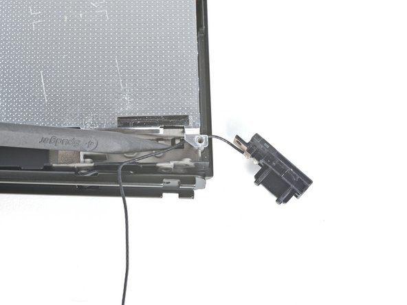
– Grab your tweezers (or your trusty fingers) and gently lift up and disconnect the primary Wi-Fi antenna’s coaxial cable.
– Reconnecting these bad boys can be a bit tricky during reassembly. Hold each connector in place over its socket one at a time, and press down with the flat end of a spudger. You’ll feel that satisfying snap when it connects.
Step 13


– Grab those tweezers or just use your fingers to gently guide the primary antenna’s coaxial cable out of its cozy slots in the shield plate. You’ve got this!
Tools Used
Step 14


– Grab your trusty Phillips driver and let’s tackle those two 4.4 mm screws holding the primary Wi-Fi antenna snugly against the shield plate. You’ve got this!
Step 15


– Slide an opening pick in between the main Wi-Fi antenna and the shield plate, just like a chef sliding a knife into a fresh loaf of bread.
– Gently pry up with the pick to pop that primary Wi-Fi antenna free from the shield plate, like lifting the lid off a treasure chest!
Step 16


– Time to say goodbye to the primary Wi-Fi antenna! Go ahead and remove it with care.
Step 17


– Grab your tweezers—or just your trusty fingers—and gently unplug the secondary Wi-Fi antenna’s coaxial cable. Easy does it!
Tools Used
Step 18


– Gently use the tip of a spudger to guide the secondary Wi-Fi antenna’s coaxial cable out of its cozy spot in the frame.
Tools Used
Step 19


– Grab your trusty Phillips driver and unscrew the 4.4 mm screw that’s holding the secondary Wi-Fi antenna snug against the shield plate. You’ve got this!
Step 20


Hold up, don’t try to fully remove the antenna just yet – its coaxial cable is still threaded through the frame, so let’s take a step back and tackle that first.
– Slide an opening pick between the secondary Wi-Fi antenna and the shield plate—take it easy, you’ve got this.
– Use the pick to gently pry up and separate the secondary Wi-Fi antenna from the shield plate. Smooth and steady wins the race!
Step 21


– Grab the pointy end of your trusty spudger and carefully guide the secondary Wi-Fi antenna’s coaxial cable out of its snug little groove in the frame.
– Gently detach and remove the secondary Wi-Fi antenna. You’re doing great!
Tools Used
Step 22


– Grab your Phillips driver and unscrew the six 4.4 mm screws holding down the shield plate. Keep those screws safe—they’re tiny but mighty!
Step 23


Don’t worry if you feel a bit of resistance – it’s totally normal. The shield plate is slightly stuck to the heat sink with thermal paste, so just take your time and gently work it loose.
– Gently lift the top of the shield plate with your fingers, pulling it away from the frame like you’re unveiling a surprise.
– Say goodbye to the shield plate as you remove it.
– You’ll notice a thick pink thermal compound connecting the shield plate to the copper heat sink below. When you take off the shield plate, don’t forget to check out our thermal paste guide to clean off the old thermal compound and swap it out for a suitable one, like K5 Pro, when putting everything back together.


Step 25


– Grab some tweezers—or just use your trusty fingers—and peel away that little piece of tape covering the daughterboard screw. Easy peasy!
Tools Used
Step 26


– Grab your trusty Phillips driver and unscrew that 4 mm screw holding the daughterboard snugly to the frame. You’ve got this!
Step 27


The underside of the daughterboard is snugly connected to the motherboard using a press connector. Keep it cool and steady as you work your magic!
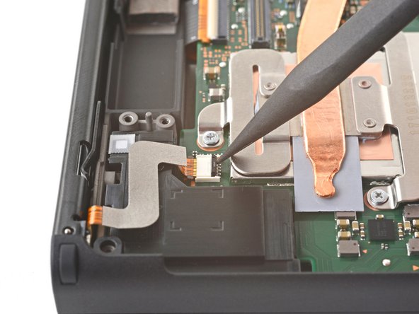
– Slide a spudger between the daughterboard and the motherboard.
– Gently pry up to disconnect the press connector and lift the daughterboard from the frame.
– Take out the daughterboard.
– When putting the press connectors back, make sure they’re aligned and press down on one side until it clicks. Then, repeat on the other side. Avoid pressing in the middle! Misalignment can bend the pins and cause serious damage.
Tools Used
Step 28

– Grab your trusty opening tool, spudger, or even your fingernail, and gently lift that little hinged locking flap on the right Joy-Con sensor rail’s ZIF connector. You’ve got this!
Tools Used
Step 29


– Grab a trusty pair of tweezers and gently tug the right Joy-Con sensor rail’s cable straight out of its connector on the motherboard. You’ve got this!
Tools Used
Step 30

– Grab your trusty Phillips driver and take out those two 3.8 mm screws that are holding the left Joy-Con sensor rail to the frame.
Step 31


– Time to put your device back together! Just follow these steps in reverse and you’ll be on your way.
– Take a moment to compare your shiny new replacement part with the original—make sure to transfer any leftover components or peel off those pesky adhesive backings before you get to installing.
– If things didn’t go quite as planned, don’t worry! Give some basic troubleshooting a shot, or feel free to reach out to our Nintendo Switch OLED Answers community for a little guidance.
– And remember, if you ever find yourself in a bind, you can always schedule a repair.
Success!