DIY Guide: Replace Earpiece in Galaxy S4 Active
Duration: 45 min.
Steps: 20 Steps
Ready to tackle that pesky earpiece issue on your Galaxy S4 Active? In this guide, we’ll walk you through the steps to swap out that faulty earpiece like a pro! If you’re struggling to hear your buddy on the other end or the call sounds like it’s underwater, then this repair is just what the doctor ordered. Let’s get started!
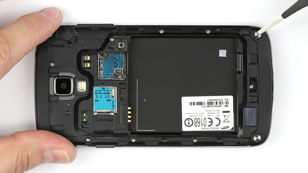
Step 1
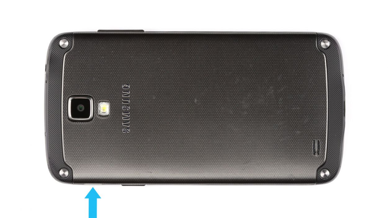
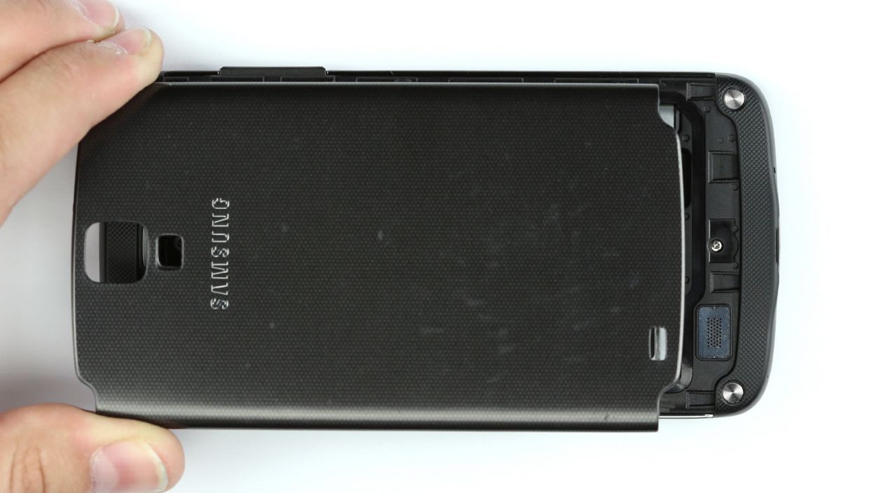
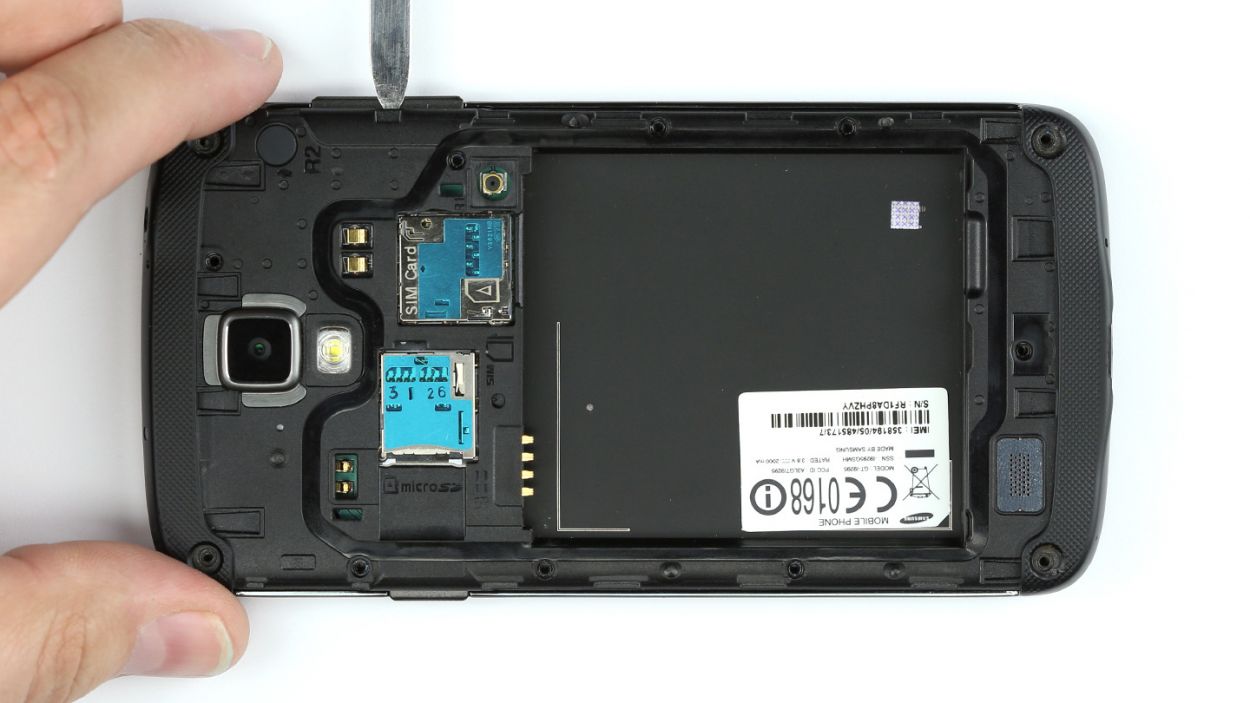
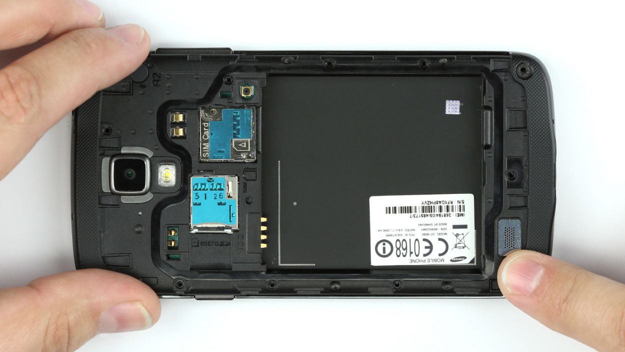
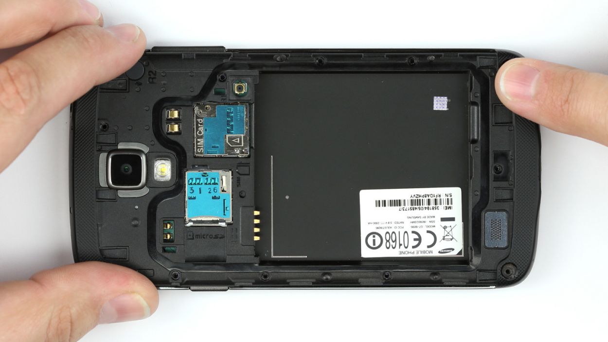
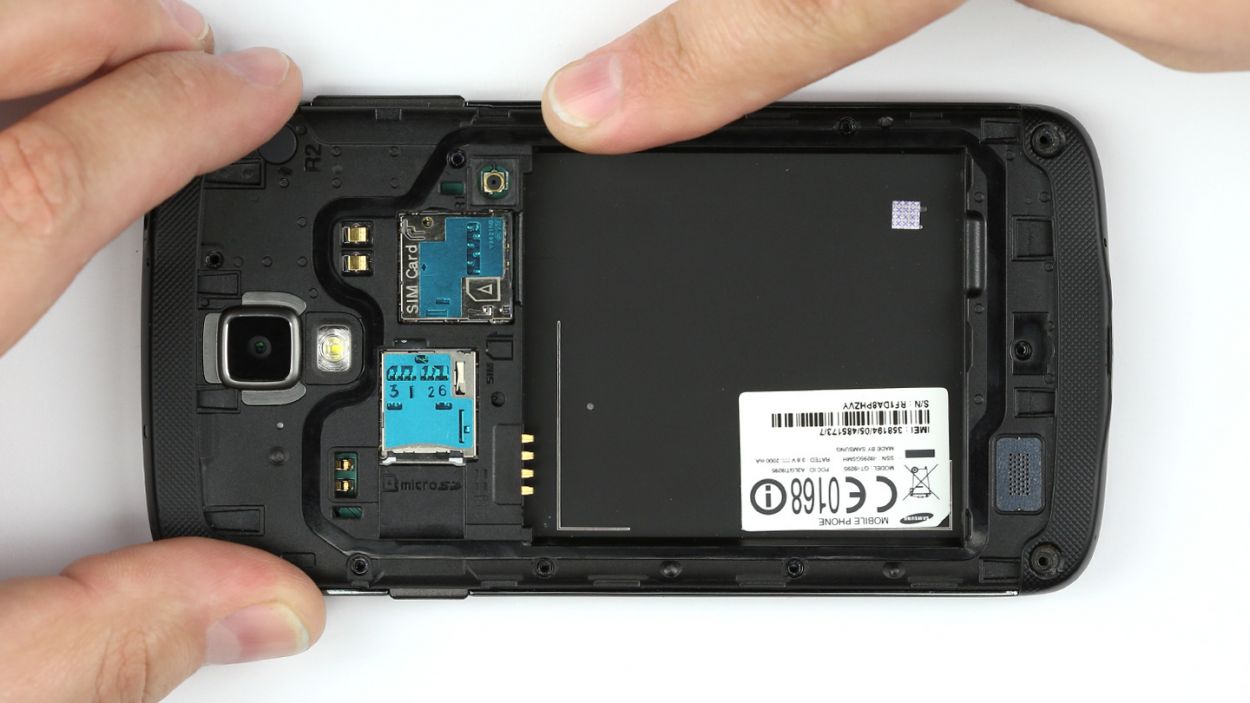
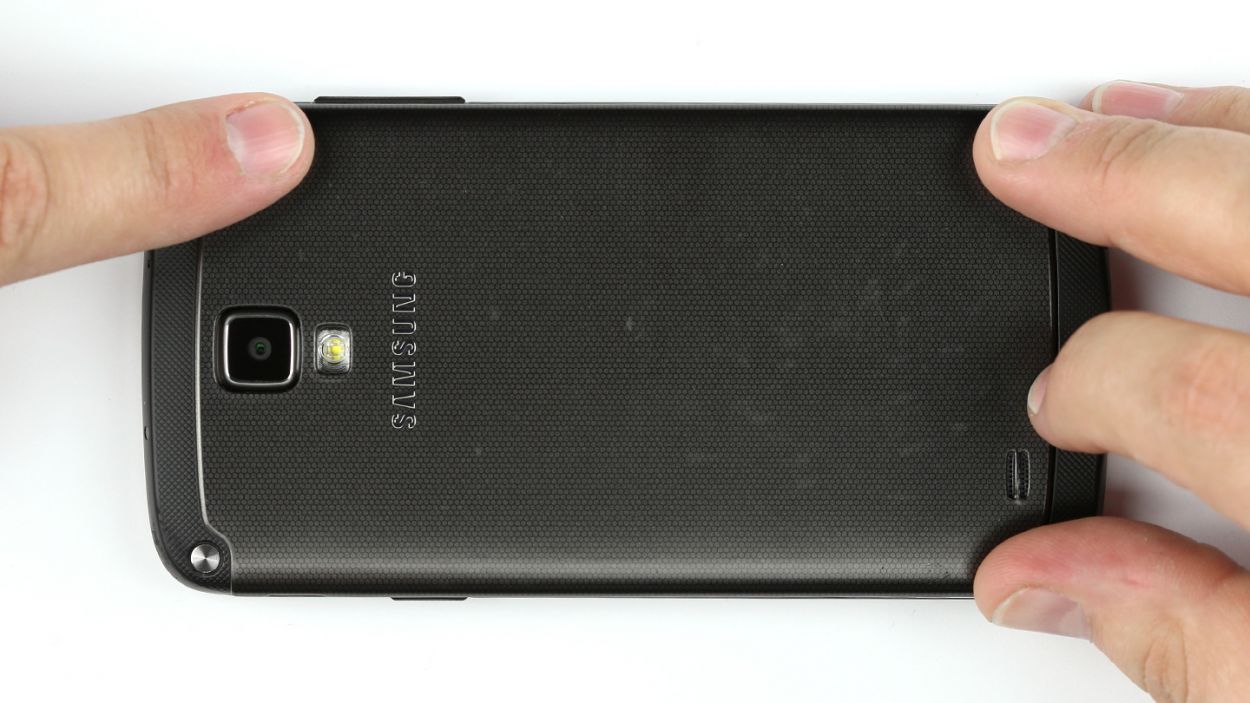
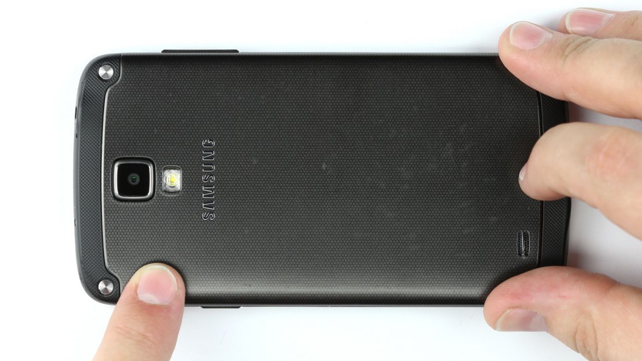
– First up, let’s tackle those sneaky little clips holding the back cover snugly to the chassis. Right above the power button, you’ll find a tiny recess just waiting for your fingernail or a trusty spudger. Give it a gentle lift here!
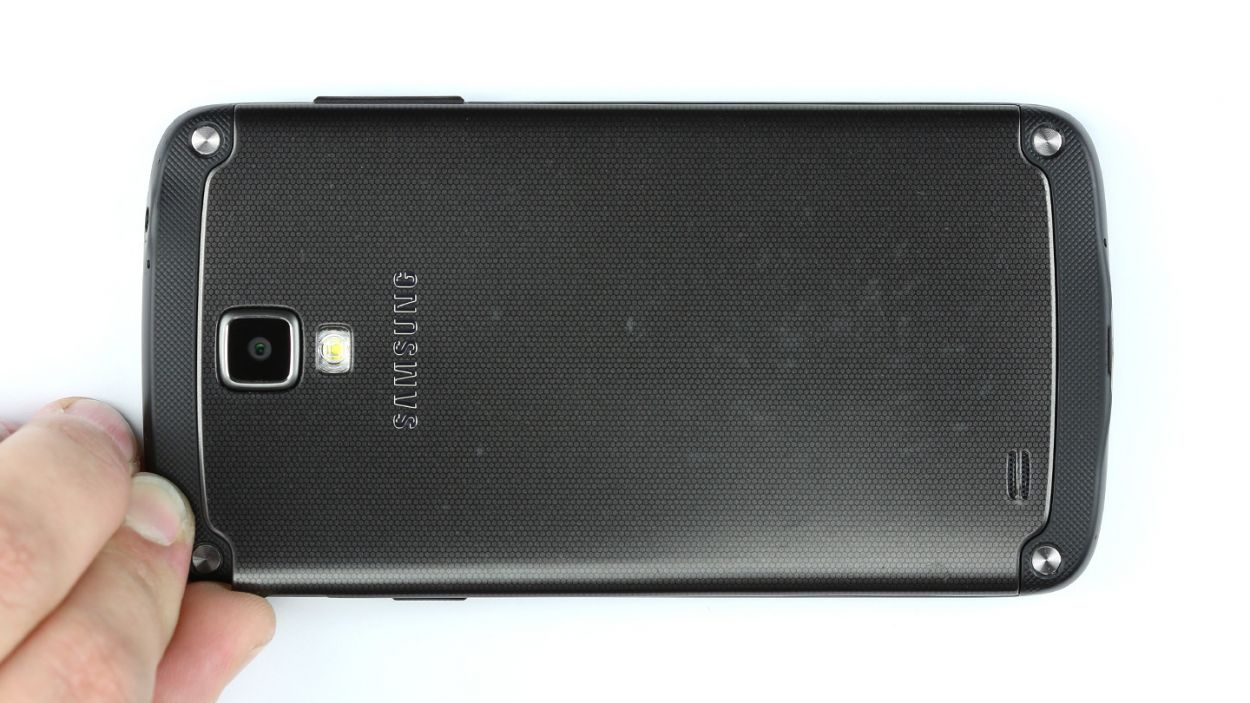
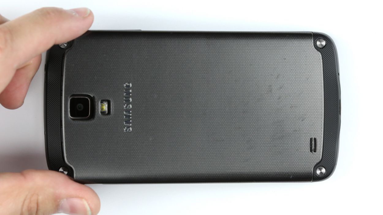
– Next, with a bit of care, disconnect the back cover from the chassis.
– Now, go ahead and remove the back cover like a pro!

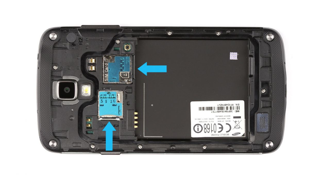
Step 3

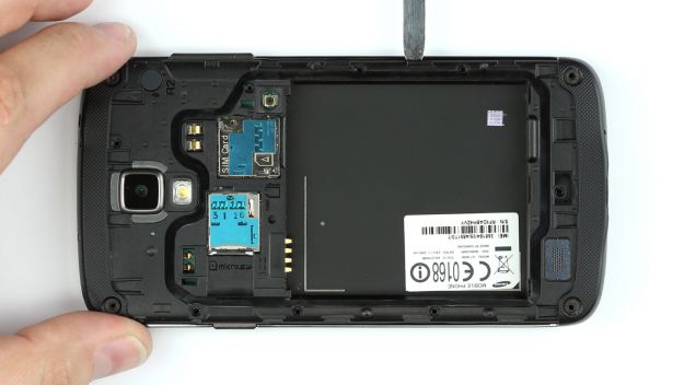
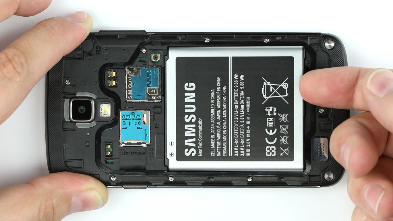
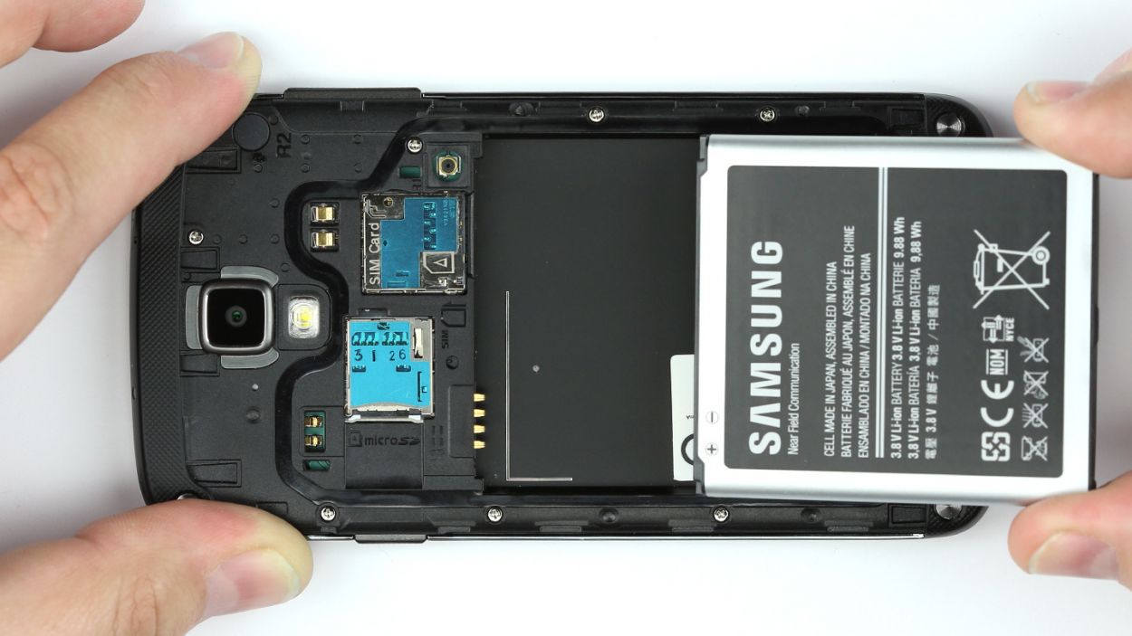
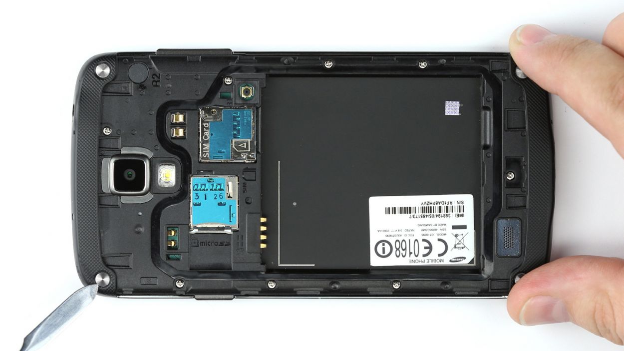
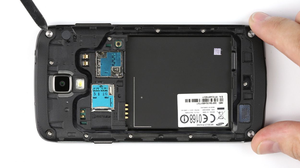
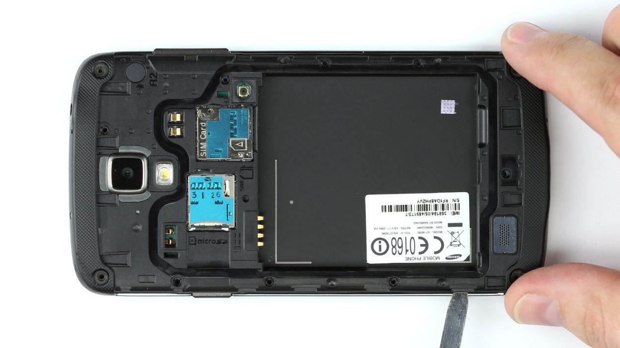
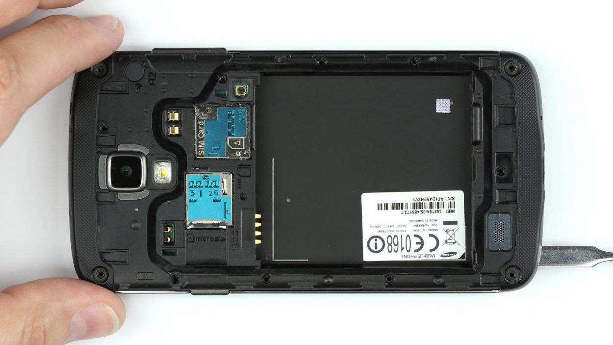
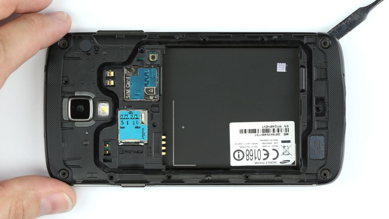
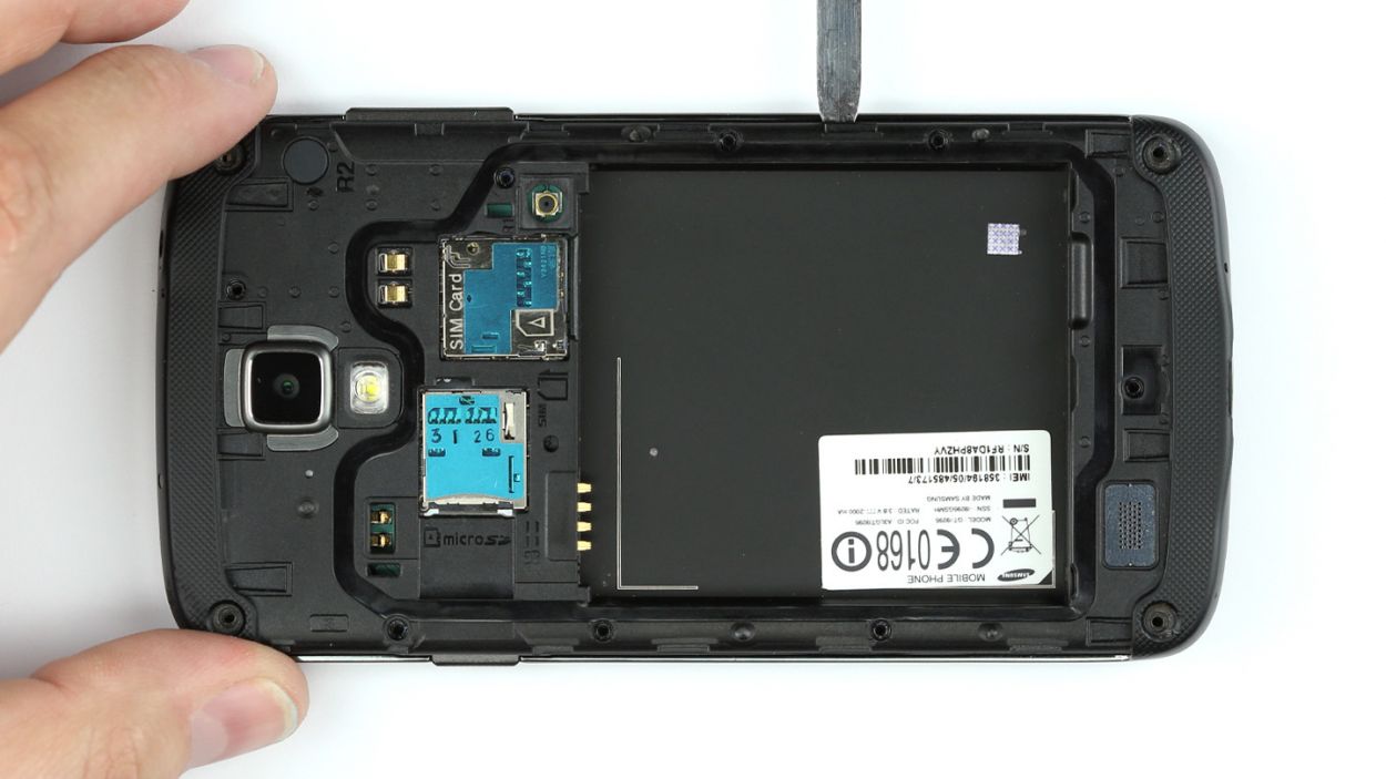
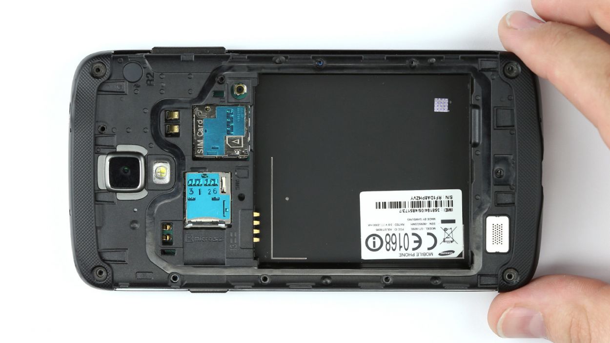
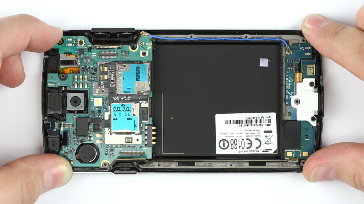
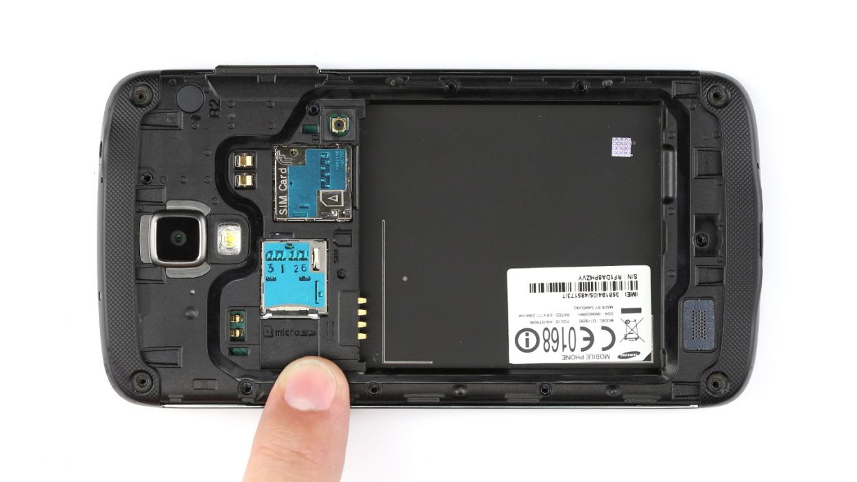
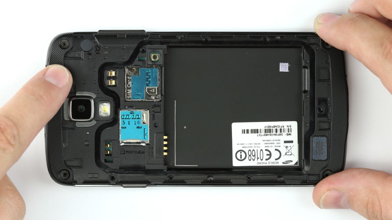
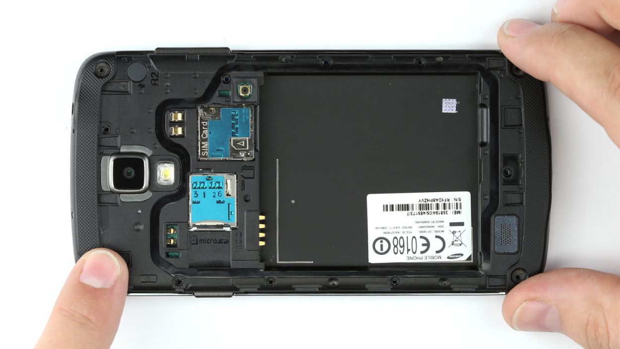
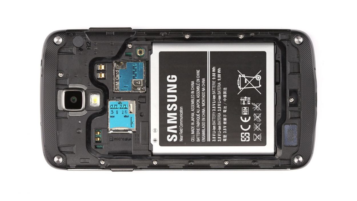
– Pop out the SIM card and microSD card like a pro!
Step 4
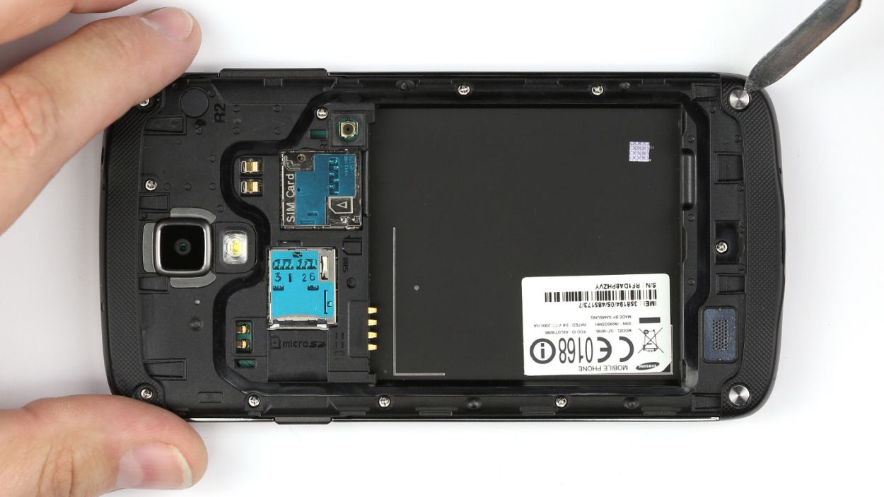
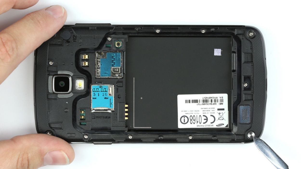
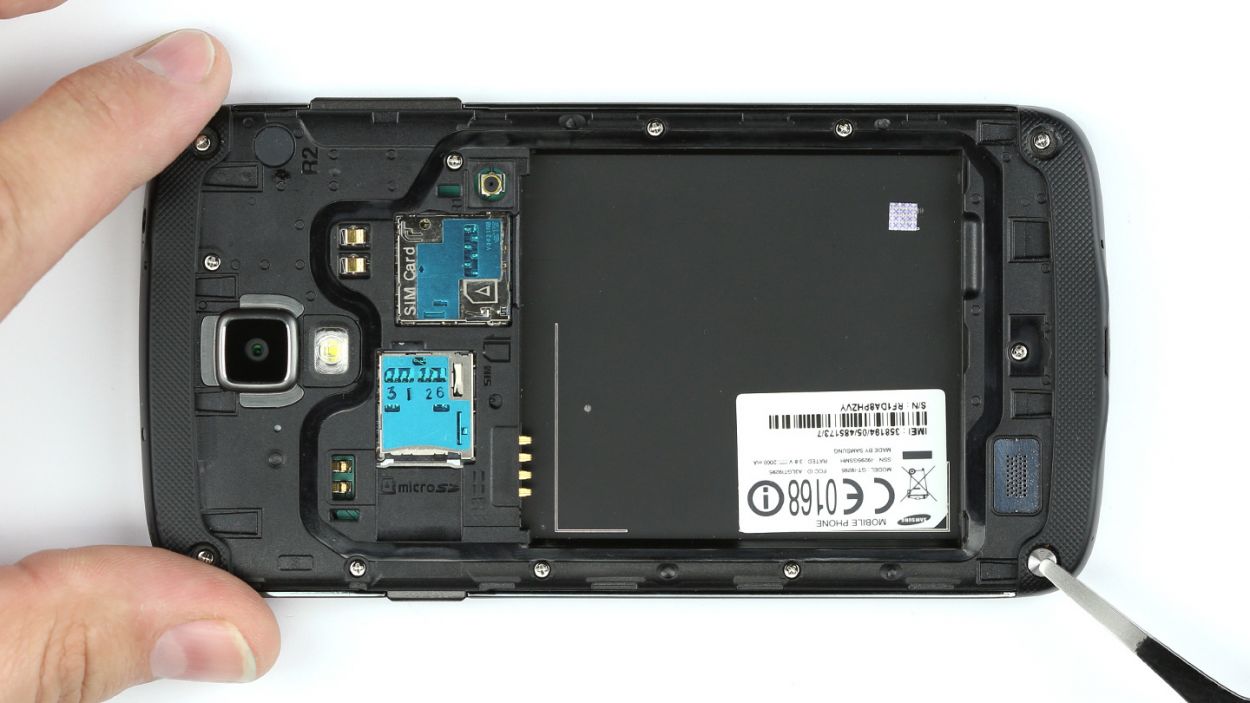
– Grab your trusty steel laboratory spatula and get ready to tackle those four metal shields! Gently slide the spatula under the covers and give them a little nudge to pop them out of their cozy spots in the chassis. It’s all about finesse—just let the tip of the spatula do the work!
Step 5
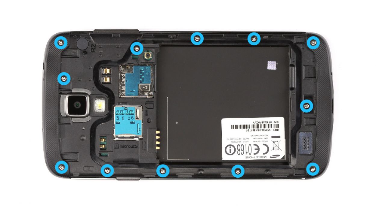
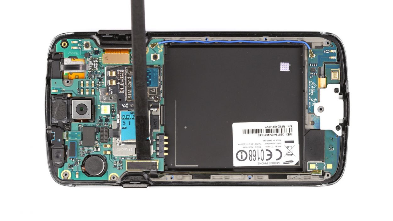
– Let’s get those twelve Phillips screws out of the way! They hold the chassis snug against the display. Grab a container to keep them safe and sound while you work. You’ll be dealing with 12 x 3.9 mm Phillips screws, so make sure you have the right tools handy. Ready, set, unscrew!
Step 6

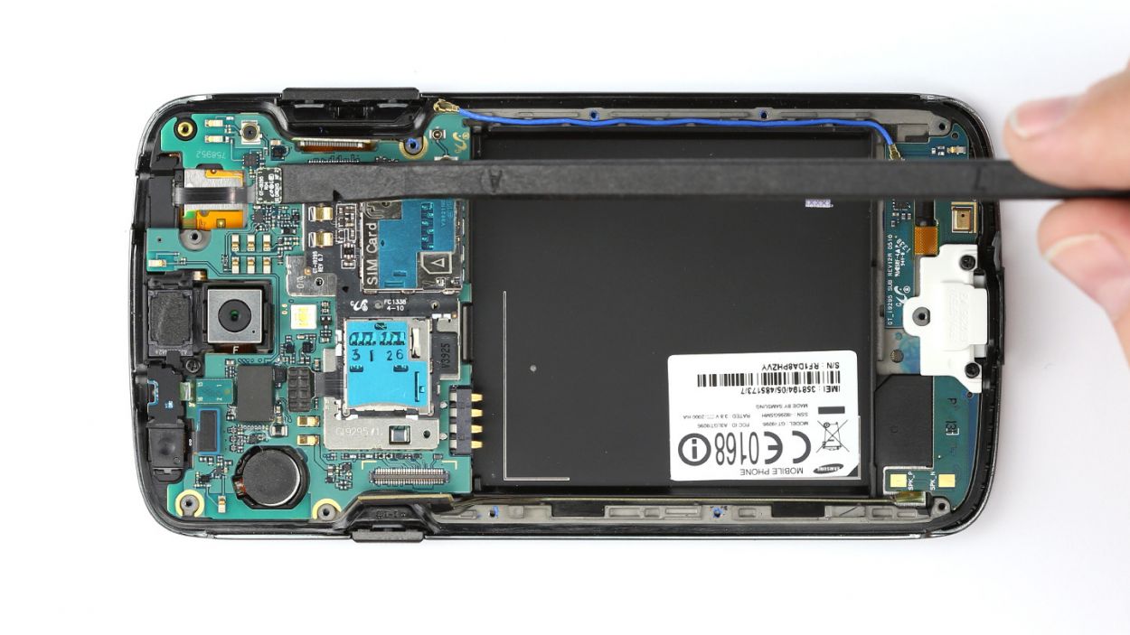
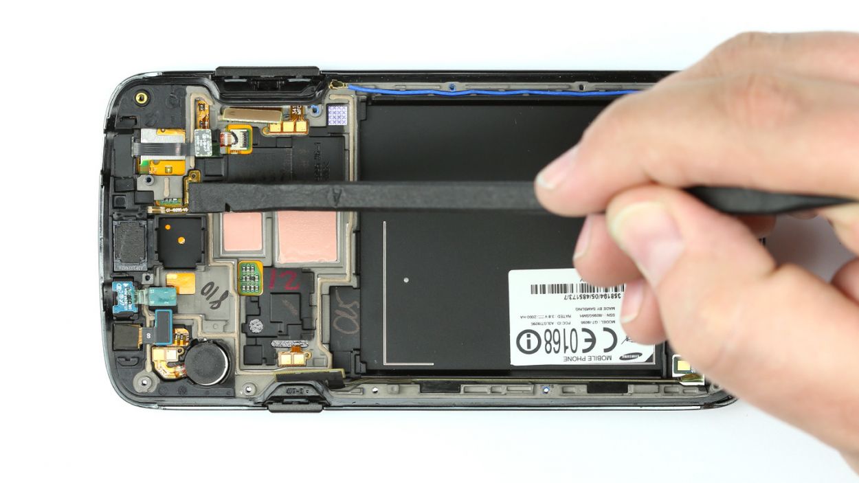
– The chassis isn’t just hanging out with the display; it’s also got some sneaky little hooks keeping it company. Grab your trusty steel spatula and let’s gently pry that chassis loose!
– Slide the spatula in between the display and the chassis. A great starting point is right at the power button—it’s like finding the sweet spot!
– Now, glide that spatula all the way around the device like you’re giving it a nice little hug.
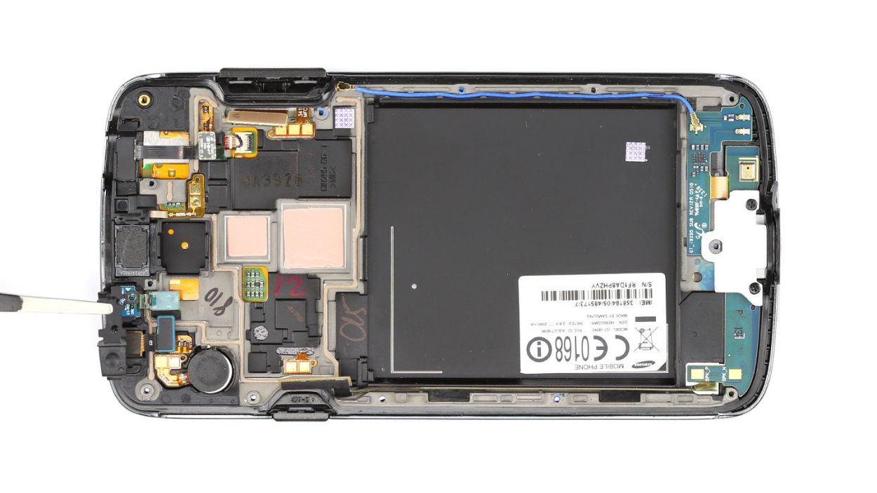
– Once you’ve successfully detached the chassis, go ahead and lift it away from the display. You’re doing great!
Step 7
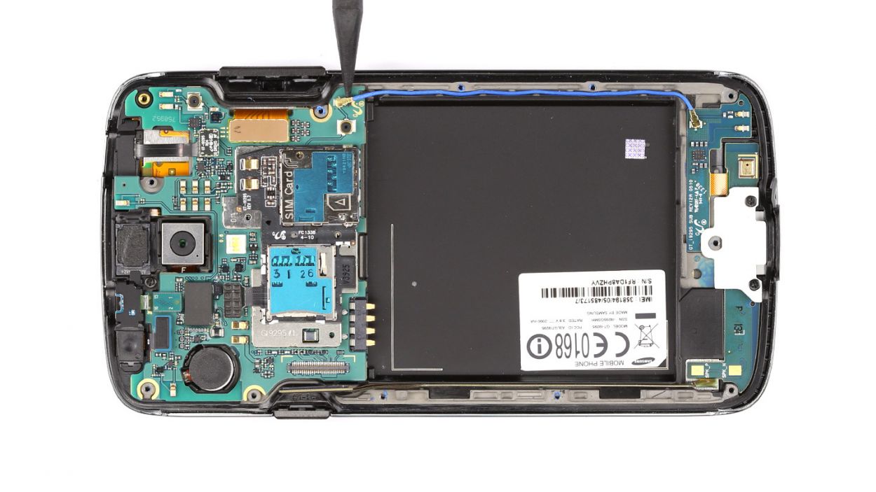
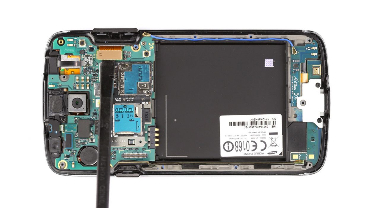
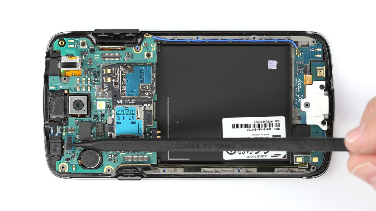
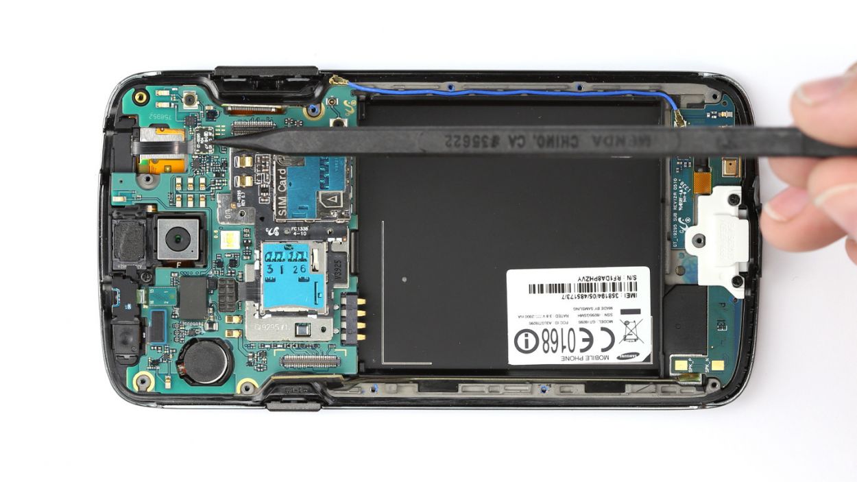
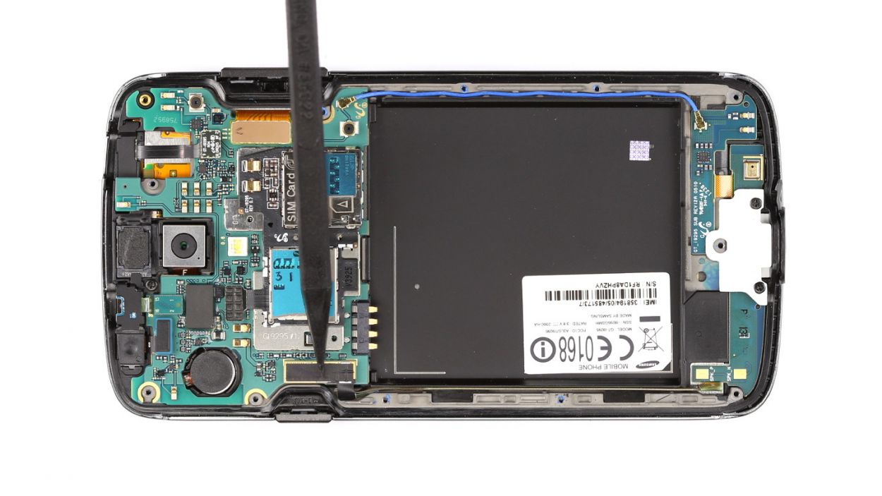
– Let’s start by unplugging the sub-board’s connection. Easy peasy!
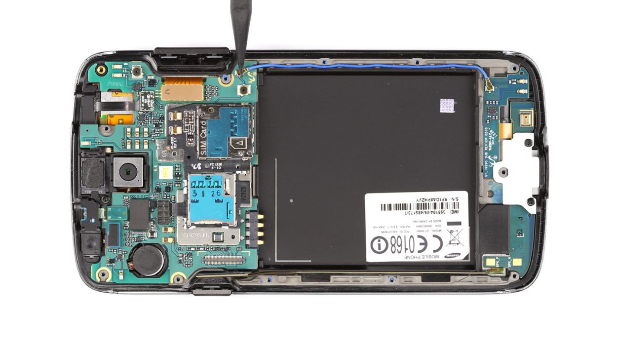
– Next up, gently detach the antenna cable. You’ve got this!
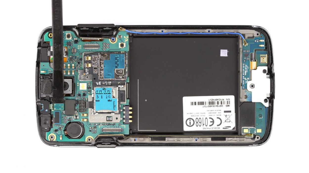
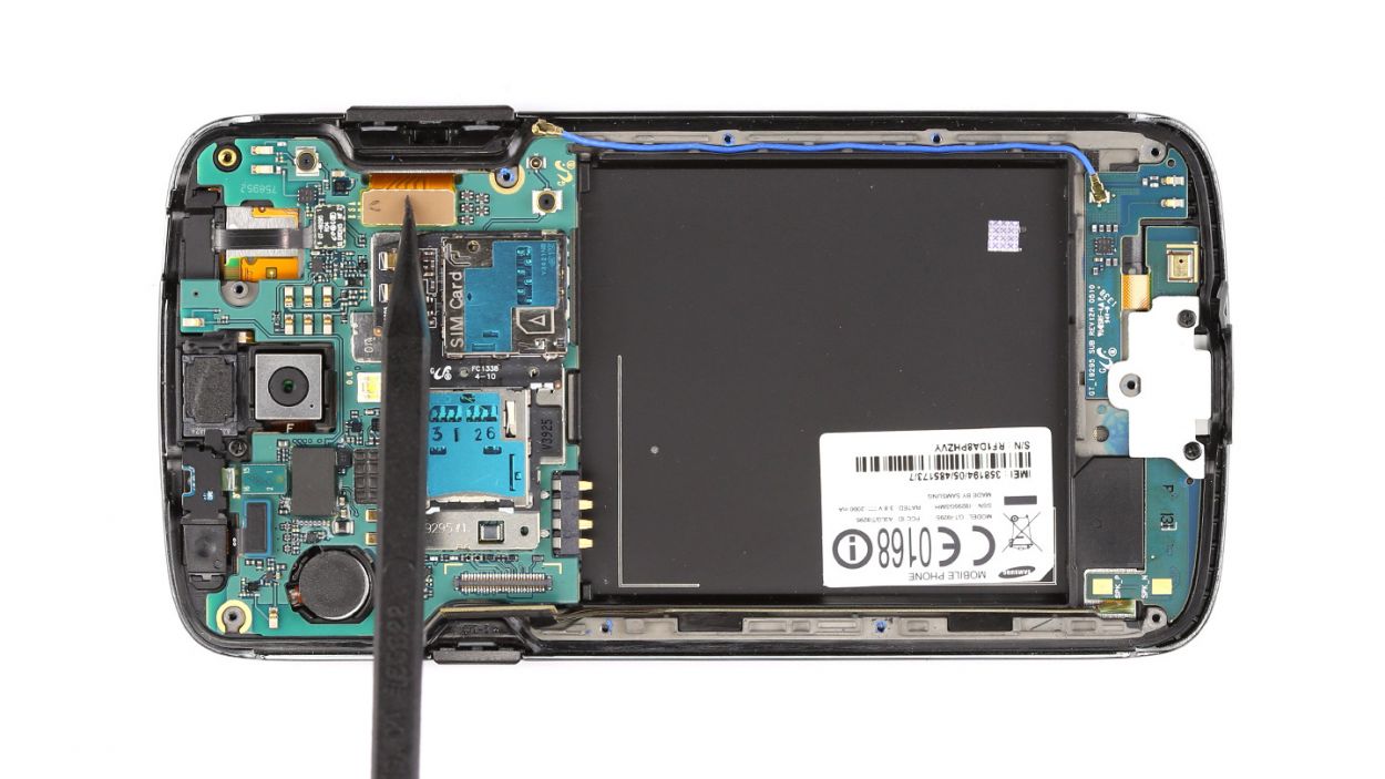
– Now, it’s time to disconnect the display connection. Keep it smooth!
– Don’t forget to unplug the brightness sensor. Bright ideas only!
– Now, let’s disconnect the proximity sensor. You’re on a roll!
– Finally, unplug the front camera connection. Almost there!
Step 8


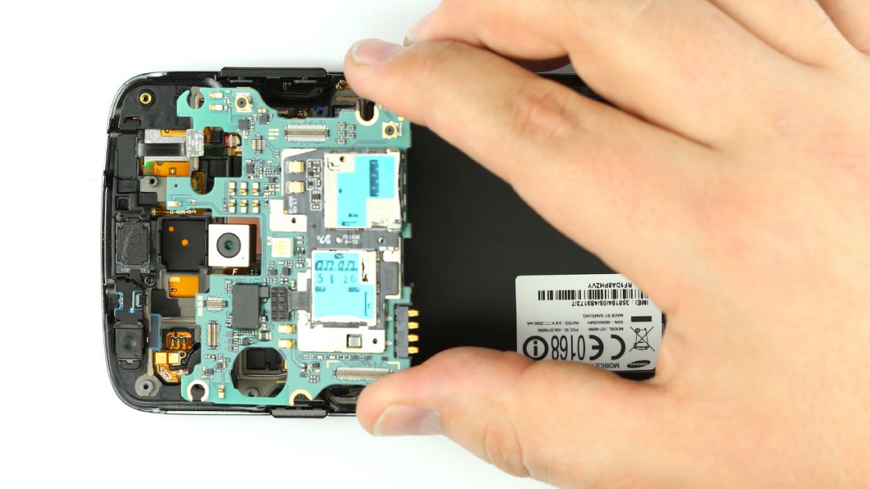
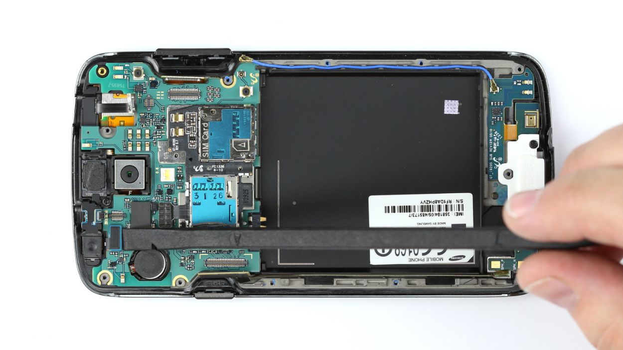
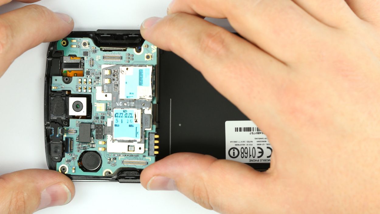
– The logic board is cozying up to the rear camera and the vibration motor. Gently nudge it towards the USB port to set it free.
– With care, lift the logic board like you’re unveiling a surprise.
– Now, slide the logic board out of its snug little home.
Step 9
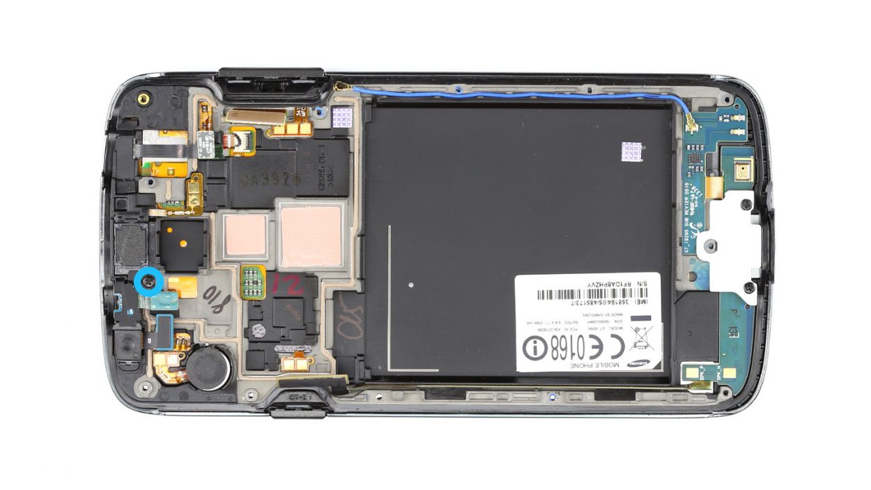

– Let’s kick things off by unscrewing that Phillips screw to free the cover plate. This little plate is holding onto the speaker, proximity sensor, and front camera like a champ! You’ll need 1 x 3.0 mm Phillips screw for this step.
– Now, gently lift off the cover from the enclosure. You’re doing great!
Step 10
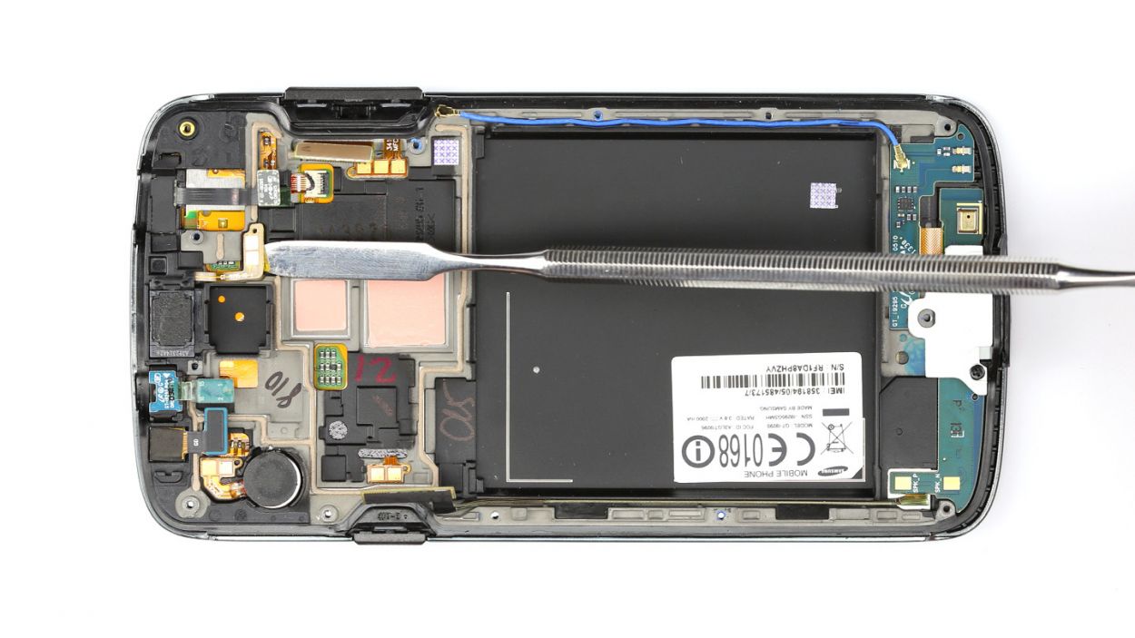

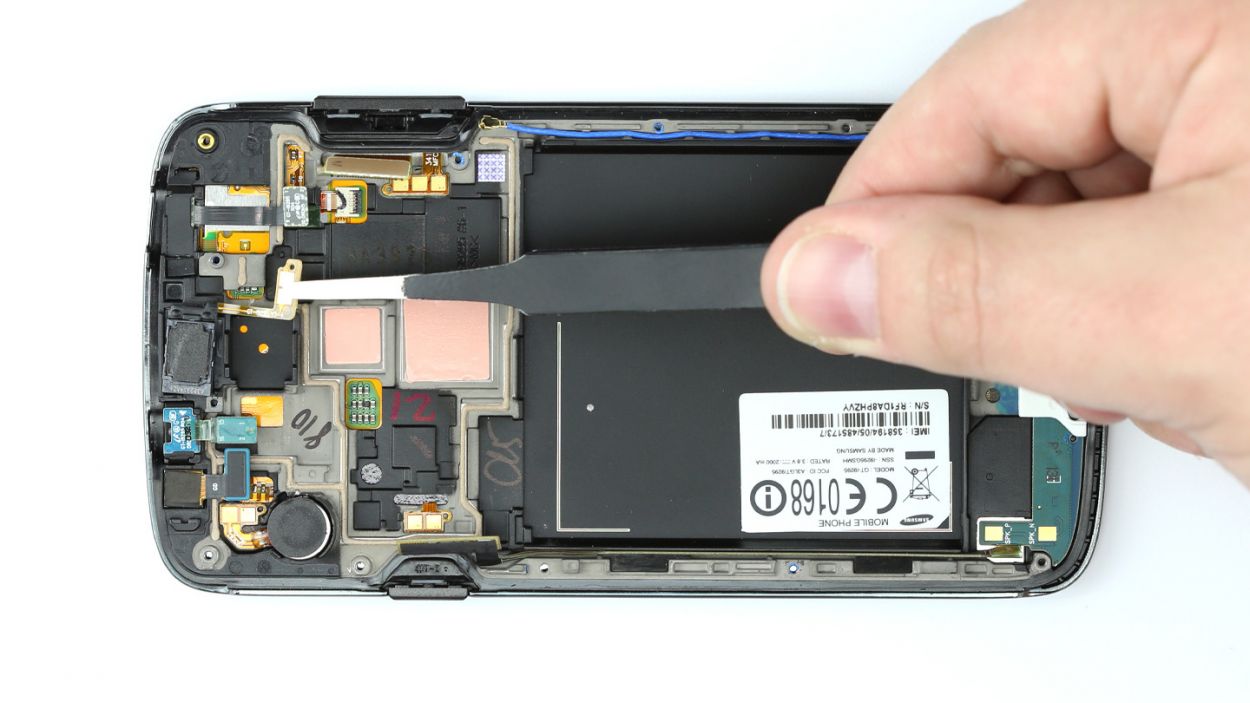
– The earpiece is stuck to the enclosure like a stubborn sticker. Grab your trusty steel laboratory spatula and gently pry it loose along with its flexible flat cable.
– Once you’re free, lift the earpiece out of the enclosure with care.
Step 11
– First up, let’s get that earpiece snugly seated in the enclosure. It’s like giving it a cozy little home!
– Now, make sure to firmly press the earpiece along with the flexible flat cable onto the enclosure. A little push goes a long way in making sure everything sticks together nicely!
Step 12

– Position the cover plate in the enclosure.
– Fasten the cover with the Phillips screw. The cover plate holds the speaker, proximity sensor and front camera in place.1 x 3.0 mm Phillips screw
Step 13

– Slide the logic board snugly into the enclosure.
– Double-check that no cables are getting pinched underneath the logic board.
– The logic board is designed to latch onto the rear camera and vibration motor. Gently nudge the logic board upwards towards the top of the enclosure until you hear that satisfying click!
Step 14

– Let’s kick things off by connecting the front camera to the logic board. You got this!
– Next up, it’s time to link the logic board to the proximity sensor. Keep it going!
– Now, go ahead and connect the brightness sensor. Bright ideas only!
– Don’t forget to connect the display. It’s like giving your device a new set of eyes!
– Now, connect the logic board to the antenna cable. Stay connected!
– Finally, let’s get that sub-board connected. You’re almost there!
Step 15

– Hey there! Just a heads up, the chassis isn’t simply held on by screws; it’s also got some little hooks giving it a snug fit with the display. Give the chassis a gentle press with your fingers to help it settle in nicely.
– Now, press the chassis down firmly across the whole device. You’ve got this!
Step 16

– Secure the chassis using the twelve Phillips screws. Grab those 12 x 3.9 mm Phillips screws and let’s get this thing locked down!
Step 17

– Grab those tweezers and gently place the four metal shields back in their cozy spots.
– Give each cover a nice, firm press to make sure they’re snug and secure.
Step 18
– Pop in the SIM card and the microSD card like a pro!

Step 20


– Let’s get that back cover snug on the chassis! First, place it right on top.
– Now, make sure the back cover hooks onto the bottom of the chassis like a pro.
– With a little gentle pressure, press down on the back cover all around so those retaining clips can snap into place. You’ve got this!