DIY Guide: Replace Nintendo Switch Fan – Step-by-Step Tutorial
Duration: 45 minutes
Steps: 27 Steps
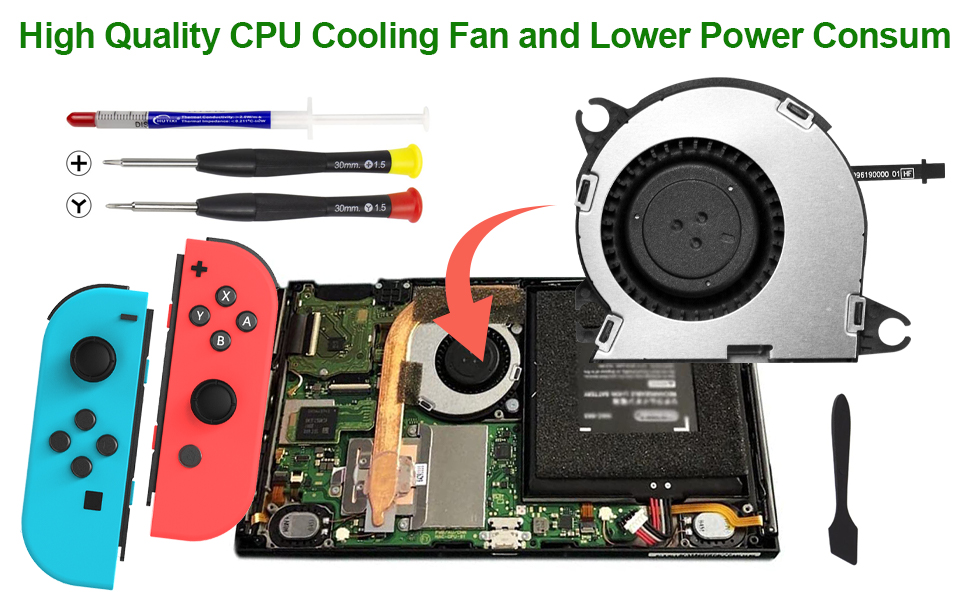
Get ready to swap out that pesky broken fan in your Nintendo Switch! While the Switch loves its JIS screws, a Phillips screwdriver will do the trick if you’re in a bind. Just be gentle with those screws—nobody likes a stripped screw! Our Phillips bits are made to work seamlessly with JIS-style screws. Quick tip: when you take off the shield plate, don’t forget to refresh the thermal compound between the plate and the heatsink. Regular thermal paste isn’t up to the task of filling big gaps, so grab some K5 Pro viscous thermal paste for the job. And just a heads up, this guide and the part we offer are perfect for both the original Nintendo Switch model from 2017 and the snazzy refreshed version from 2019 (model numbers HAC-001 and HAC-001(-01), respectively). If you hit a snag, remember you can always schedule a repair!
Step 1


Before diving into this repair, be sure to power down the device completely.
– Grab the small round button on the back of the Joy Con controller and give it a good press and hold.
– While you’re holding it down, gently slide the controller upward to release it.
Step 2


Do the same cool moves for the other Joy Con too.
– Keep sliding that Joy Con up until it pops right off the console! You’ve got this!
Step 3

During this repair, make sure each screw returns to its original spot. Keep track of them as you go!
– Grab your Y00 screwdriver and zip those four 6.3 mm screws out of the back panel.
Step 4


To avoid those screws from getting stuck, apply some steady pressure, take your time, and if the screws are still playing hard to get, try a different JIS 000 or PH 000 driver.
– Grab your trusty JIS 000 screwdriver or the sleek PH 000 driver, and let’s unscrew a bit of that rear panel:
– One screw, 2.5 mm long, located on the top edge of the device—easy peasy.
– Two screws, also 2.5 mm long, hanging out on the bottom edge—let’s get those out too!
Step 5


– Let’s get started! Use a JIS 000 screwdriver or an official PH0000 driver to remove the two 3.8 mm center screws, one on each side of the device. Easy does it!
Step 6


Before diving into the next step, make sure to pop out that microSD card from its cozy little slot. Let’s keep things smooth sailing!
– Give that kickstand a little nudge with your finger and flip it up from the back of your device. You’ve got this!
Step 7

– First, grab your trusty JIS 000 screwdriver – or an official PH0000 driver, we won’t judge – and carefully remove the 1.6 mm screw hiding out in the kickstand well. Easy peasy!
– Now, go ahead and close that kickstand. You’re making great progress!
Step 8


The game card cartridge flap is like a trusty sidekick, keeping the other half of the plastic shell secure. So, if it’s closed, it might just put the brakes on lifting that rear panel all the way up!
– Pop open that game card cartridge flap like a pro!
– Gently lift the rear panel from the bottom of your device and take it off with care.
Step 9

– Let’s get started! Use a JIS 000 screwdriver or an official PH0000 driver to carefully remove the 3.1 mm screw that’s holding the microSD card reader in place. Easy does it!
Step 10


– Gently grab the microSD card reader with your fingers or a pair of tweezers and lift it straight up—smooth and steady does it—to disconnect and remove it from the device.
– When putting things back together, make sure the press connector under the foam pad is snugly connected to the motherboard. Pro tip: peeling off the foam pad first can make reinstalling the card reader a breeze.
Tools Used

Step 11

– Grab a JIS 000 screwdriver or a PH 000 driver and carefully unscrew the six 3 mm screws holding the shield plate in place. Keep those screws safe—they’re small but mighty!
Step 12


If the foam isn’t coming off easily, don’t go all Hulk on it! Take your time, try peeling from other spots, and gently work it loose without tearing.
– Gently peel back the foam at the top edge near the fan exhaust port—use your fingers or tweezers if needed. You’re doing great, keep it steady!
Tools Used
Step 13


A generous layer of pink thermal compound is doing its job, filling the space between the shield plate and the copper heat sink below. This little hero helps keep the Switch cool and collected, preventing any overheating drama.
You might notice a bit of resistance when you’re working with it. No worries, that’s just the shield plate being a little clingy to the heat sink thanks to the thermal paste. It’s all part of the process!
– Slide a spudger under the shield plate along the device’s edge.
– Pry up gently to lift and remove the shield plate from the device.
– You can reuse the pink thermal compound if you’re careful. Keep it clean and ensure it makes solid contact between the heat sink and the shield during reassembly.
– If it needs replacing, check out our thermal paste guide to remove the old compound and apply a new one, like K5 Pro, during reassembly.
Tools Used

Step 14


– Grab your trusty spudger and gently pop the battery connector straight up out of its snug little home on the motherboard. Take it slow, and you’ll be golden!
Tools Used
Step 15

– Grab your JIS 000 screwdriver or the official PH 000 driver, and pop out those three 3 mm screws holding the heat sink to the motherboard. Easy peasy!
Step 16
The foam is super delicate and can tear easily. Use this technique to carefully peel it off:
Just peel the foam back far enough to free up the fan—no need to go overboard!
– Gently lift the two foam pieces covering the heatsink and the fan away from the fan.
– Slide the tip of a spudger under the part of the foam that isn’t stuck to anything.
– Hold the top of the foam in place with your finger.
– Roll the spudger tip under the foam all the way to the other end to free it.
Tools Used
Step 17


Feeling a bit of pushback? Totally cool, just the heat sink being a clingy friend to the CPU with thermal paste.
– Grab your trusty spudger or just your fingers and gently lift that heatsink off the motherboard. It’s time to set it free!
– Wave goodbye to the old thermal paste on the heat sink and CPU! Use some high-concentration (90% or higher) isopropyl alcohol and a microfiber cloth to give them a good clean. Don’t forget to apply a fresh layer of thermal paste to the CPU before putting everything back together.
– Make sure to spread that thermal paste on all the surfaces that had it before. This includes the area between the heatpipe and aluminum shield, which helps the Switch keep its cool.
Tools Used

Step 18


– Grab your trusty opening tool or just your fingernail, and gently lift that little hinged locking flap on the digitizer cable’s ZIF connector. You’ve got this!
Step 19


Don’t try to cram the cable into the connector. If it’s not going in, check that the locking flap is up, adjust the cable, and give it another go!
If your touchscreen is acting up after the repair but the Game Card reader is working fine, double-check that this cable is snugly plugged in. If the Game Card reader is also on strike, hop to the next step and take a look at the Game Card connector instead.
– Grab your trusty tweezers and carefully nudge the digitizer cable sideways to slide it out of its connector on the game card reader board. Take it slow—no rush!
– Before you pop the cable back in during reassembly, double-check that the ZIF connector’s locking flap is in the open position. Flap up, party on!
– When you’re ready to reconnect, keep the cable nice and parallel to the board. Gently guide it into its connector—easy does it!
Tools Used
Step 20


If your touch screen is playing hard to get or those game cards are pulling a disappearing act after putting everything back together, it’s possible that this pesky press connector didn’t get the memo about reconnecting. Gently unplug it and give it another shot—let’s get that device back in action!
– Grab your trusty spudger and gently nudge the headphone jack and game card reader connector straight up to disconnect it from the motherboard. Easy peasy!
– When it’s time to reconnect, just align those connectors like a pro! Press down on one side until you hear that satisfying click, then do the same on the other side. Remember, no pressing down in the middle! If things get misaligned, those little pins can bend and that’s a no-go. If you find yourself in a pickle, don’t hesitate to schedule a repair.
Tools Used
Step 21

– Grab your trusty JIS 000 screwdriver or the official iFixit PH 000 driver and let’s get to work! Carefully unscrew those three 3.1 mm screws that are holding the headphone jack and game card reader board snugly in place. You’ve got this!
Step 22


– Grab a trusty pair of tweezers or just your fingers and gently lift out that headphone jack bracket. You’ve got this!
Tools Used
Step 23


– Grab a trusty pair of tweezers or just your fingers to gently pop out the headphone jack and game card reader board. You’ve got this!
Tools Used
Step 24


– Use an opening tool, spudger, or your fingernail to flip up the small, hinged locking flap on the fan cable ZIF connector.
Tools Used
Step 25


– Grab your tweezers and gently wiggle the fan cable straight out of its connector on the motherboard—you’re almost there, keep it steady!
Tools Used
Step 26

– Grab your trusty JIS 000 screwdriver or the official iFixit PH 000 driver and let’s tackle those three 4.8 mm screws holding the fan in place. You’ve got this!
Step 27


Take a moment to compare your shiny new replacement part with the original one. If there are any leftover components, like those little rubber bushings, you might need to move them over to the new part before getting it all set up. Just a quick swap and you’ll be good to go!
– Now that you’ve finished, just reverse the steps to put everything back together. You’ve got this!
– Got e-waste? Be sure to take it to a certified recycler like anR2 or e-Stewards for a proper send-off.
– Things not going quite as planned? No worries! Try a little troubleshooting, or if you’re stuck, feel free to reach out to our community for some tips.
– And hey, you made it through! If you’re feeling unsure about any of it, don’t hesitate to schedule a repair.
Tools Used
Success!