DIY Guide: Replace Samsung Galaxy S6 Edge USB Connector
Duration: 45 min.
Steps: 10 Steps
In this guide, we’ll walk you through the steps to swap out that pesky, faulty USB connector on your Samsung Galaxy S6 Edge. If your computer is giving you the silent treatment when you connect your phone, or if charging feels like a lost cause, this repair is just what you need. Let’s get started!
Step 1
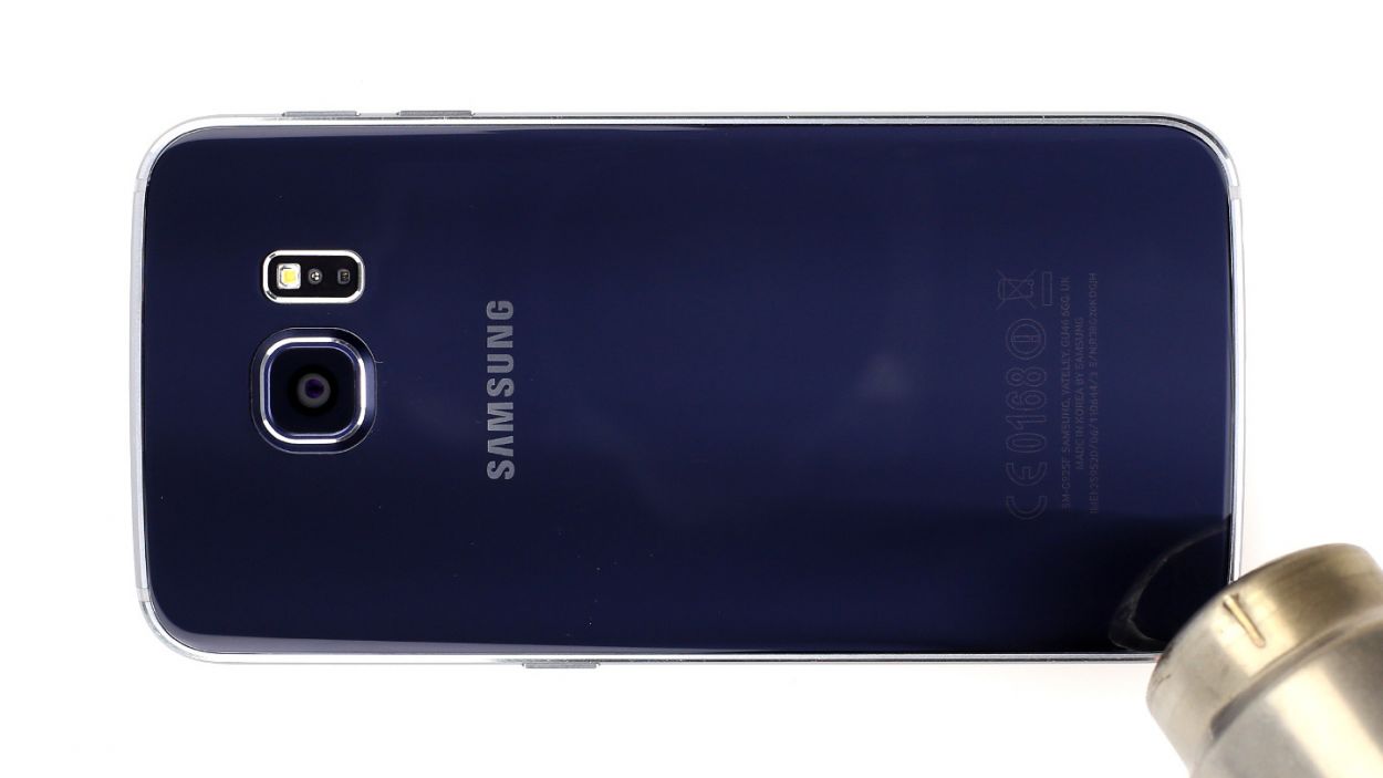
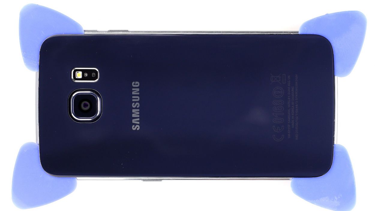
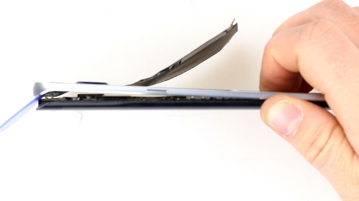
– The back of the Samsung Galaxy S6 Edge is stuck on there pretty well, thanks to some strong glue. To get it off, you’ll want to warm it up with a heat gun to soften that adhesive. Once it’s nice and toasty, grab a plastic pick and gently slide it into the tiny gap between the frame and the glass to break the seal.
– Speaking of that gap, it’s pretty narrow! So, make sure to use a flat, sturdy tool to help you get in there without any fuss.
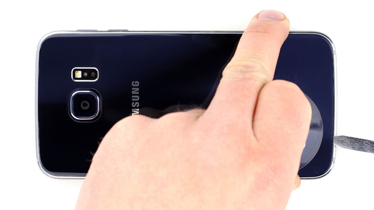
– Now, with a suction cup in hand, carefully lift the back cover. Take your time; we want to keep everything intact!
– As soon as you see a little opening, slide that plastic pick in there to protect the aluminum from any accidental damage.
Step 2

The inside of the back cover has a nice coat of paint! When you’re removing any leftover adhesive, be gentle—nobody wants scratches or cracks to crash the party!
– Gently slide the pick about two or three millimeters between the back cover and the frame—this helps keep everything inside happy and undamaged! Remember, the inside of the back cover is painted, so take your time removing any sticky leftovers to avoid scratches or cracks.
– The back cover of the Galaxy S6 Edge is glued around the whole outer edge. It’s like a little glue party! So, take that pick and glide it all the way around the phone to break the seal.
– Once you’ve loosened all the glue, you can carefully lift the back cover off. You’ve got this!
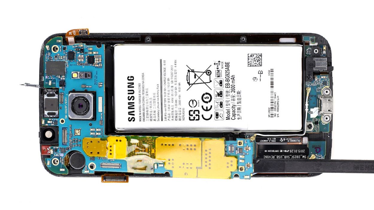
Step 3
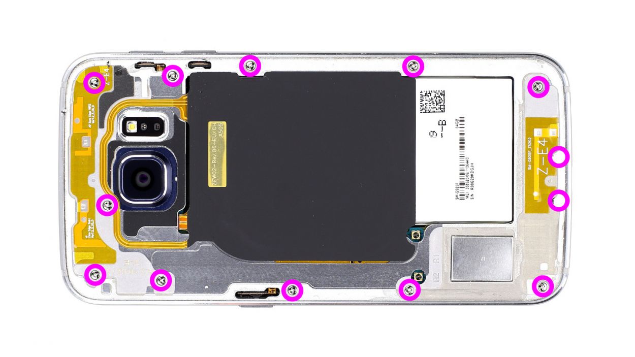
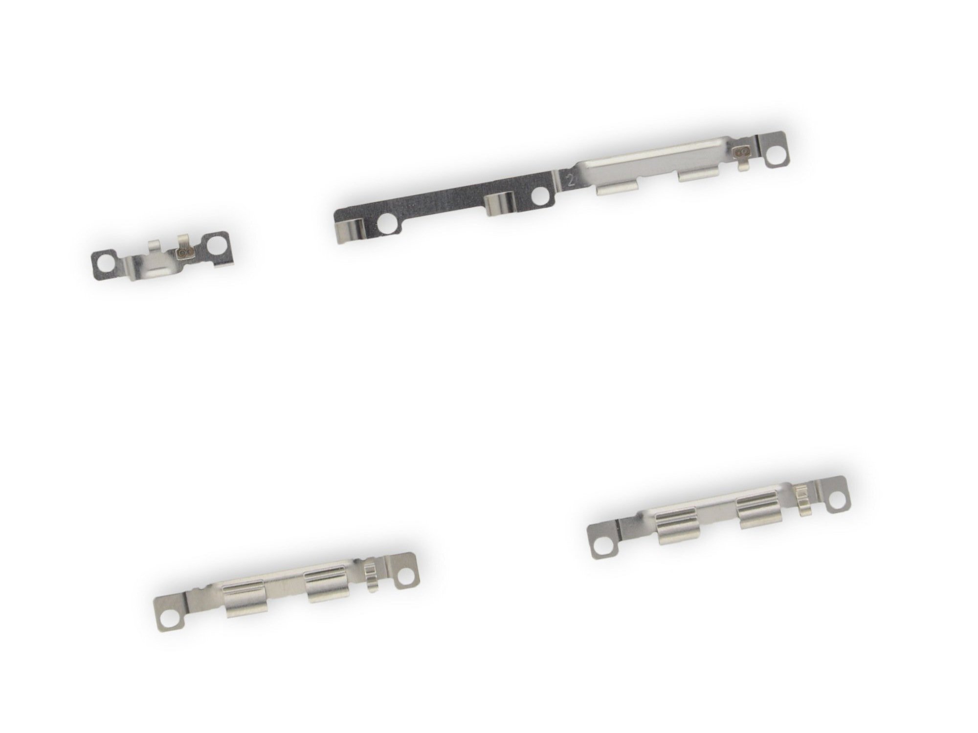
– First things first, let’s tackle those 13 Phillips screws holding the plastic cover snugly in place (check out figure 1 for a visual guide). They’re 13 x 3.3 mm Phillips screws, so grab your trusty screwdriver!
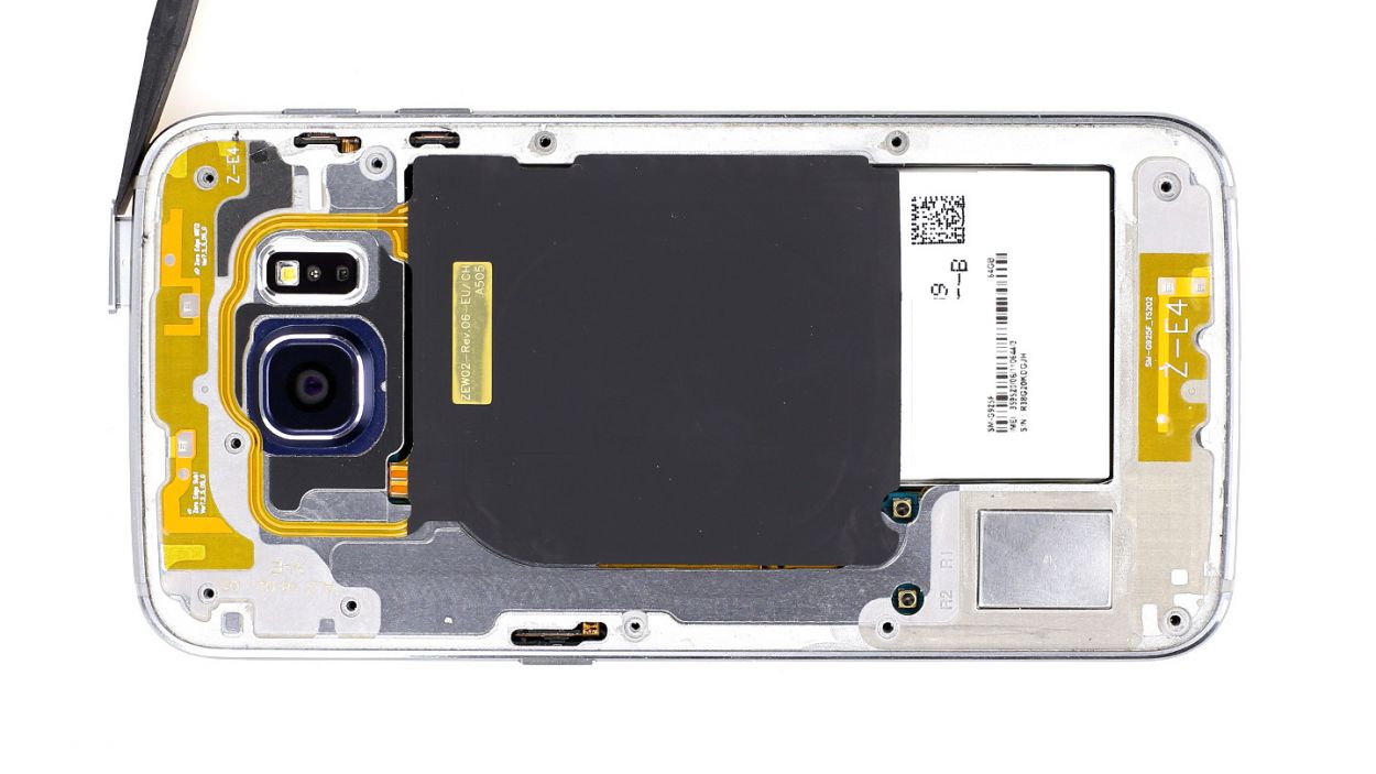
– Next up, gently pop out the SIM card tray. It’s a quick and easy step!
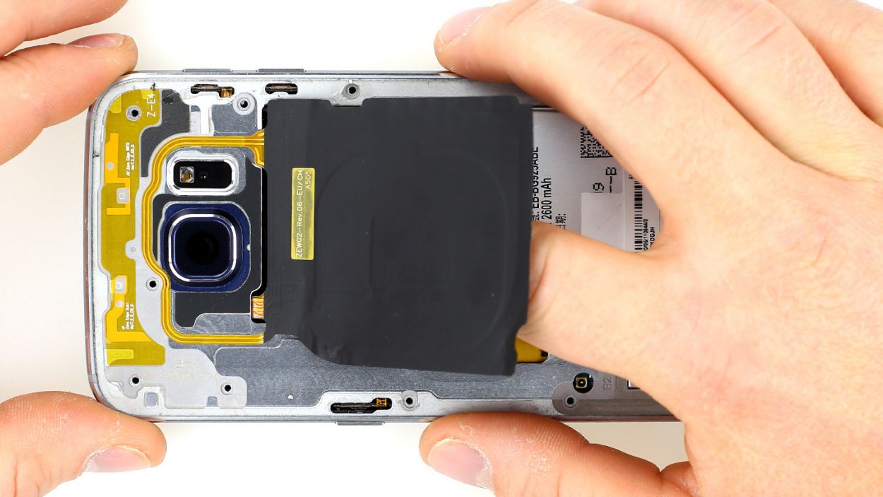
– Now, let’s lift the charging pad for wireless charging. It’s just a little bit glued to the midframe, so a gentle nudge should do the trick.
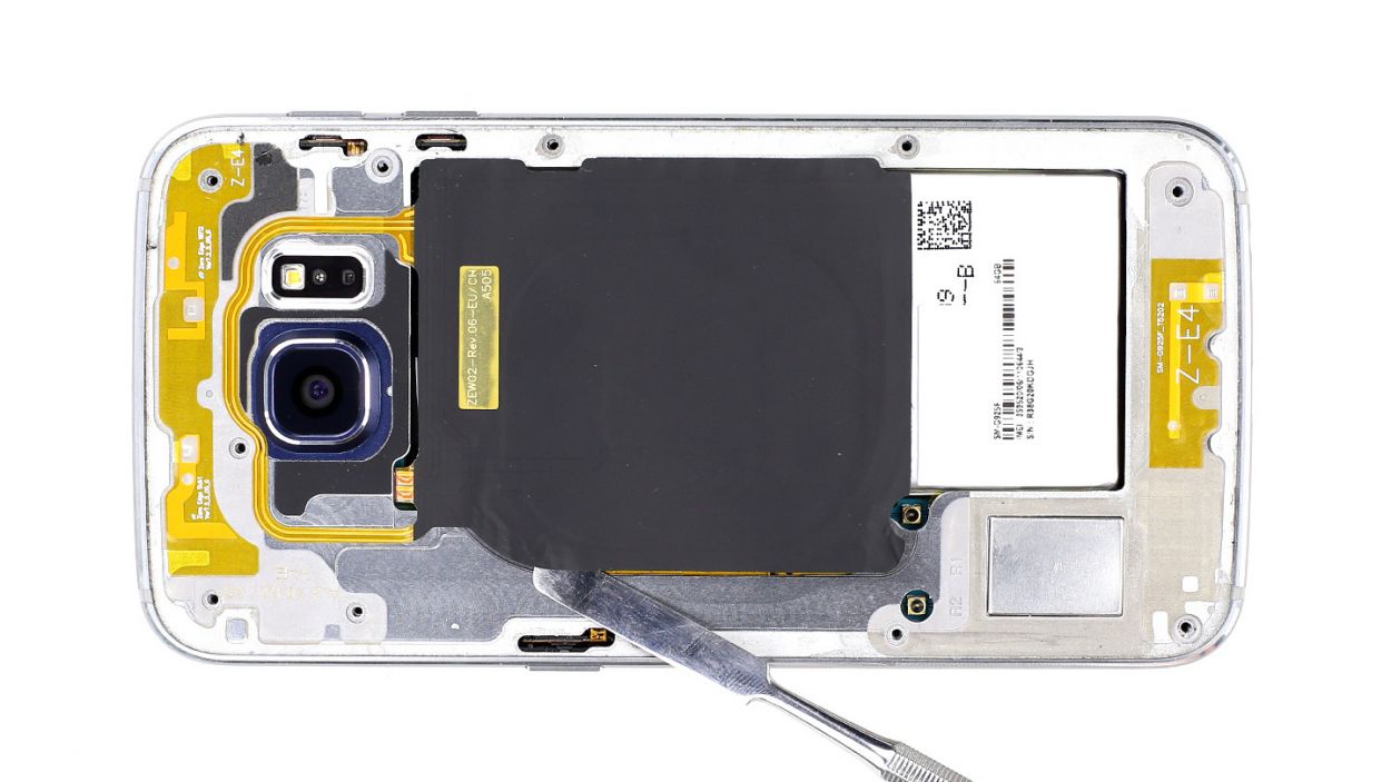
– To remove the midframe, you’ll need to give the battery and the rest of the smartphone a little push downwards. With your other hand, push up on the frame. If it’s feeling stubborn, don’t hesitate to slide a pick between the display and the frame and give it a little upward press.
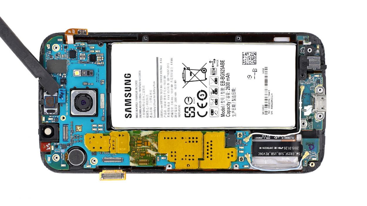
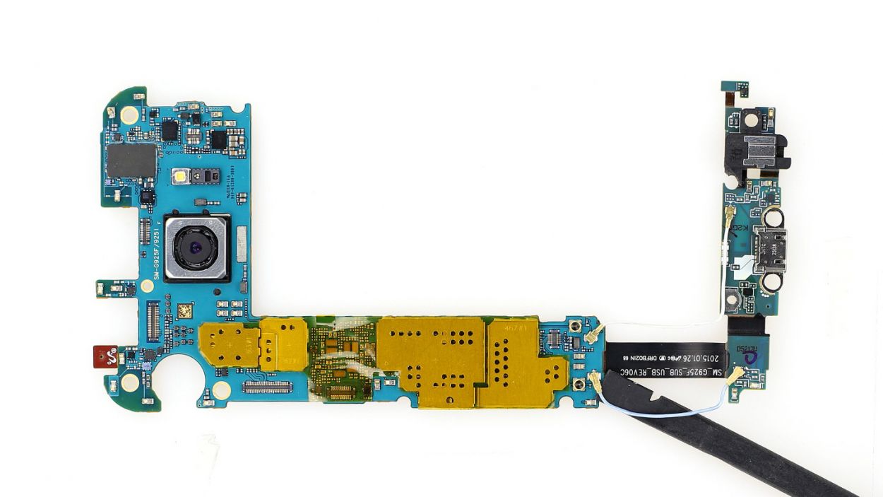
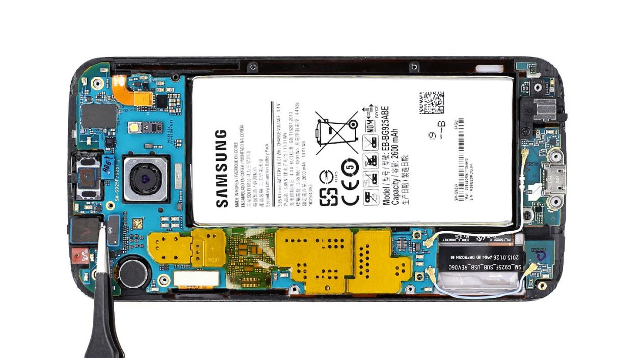
Step 4

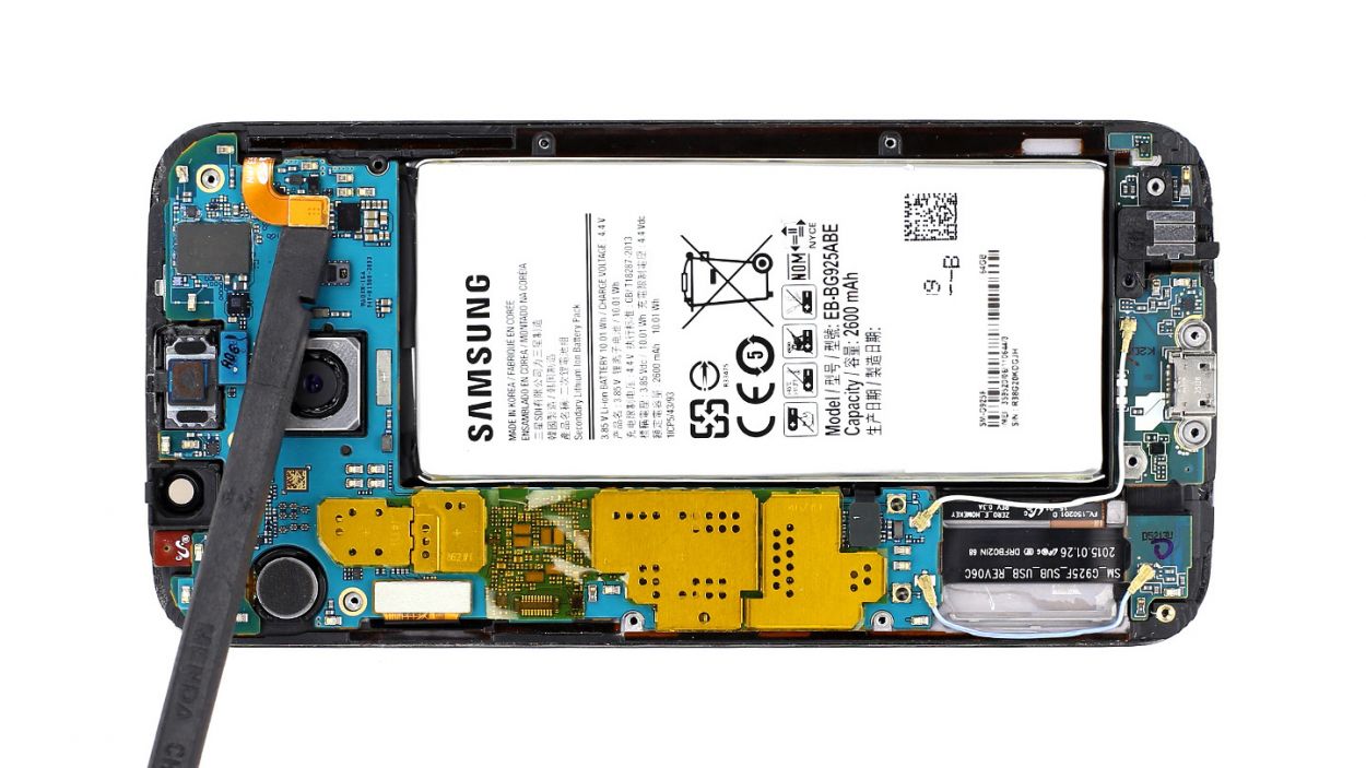
– Gently slide the sharp end of the spudger just below the contact and give it a little lift. Remember, we want to keep those resistors attached to the logic board, so be careful!
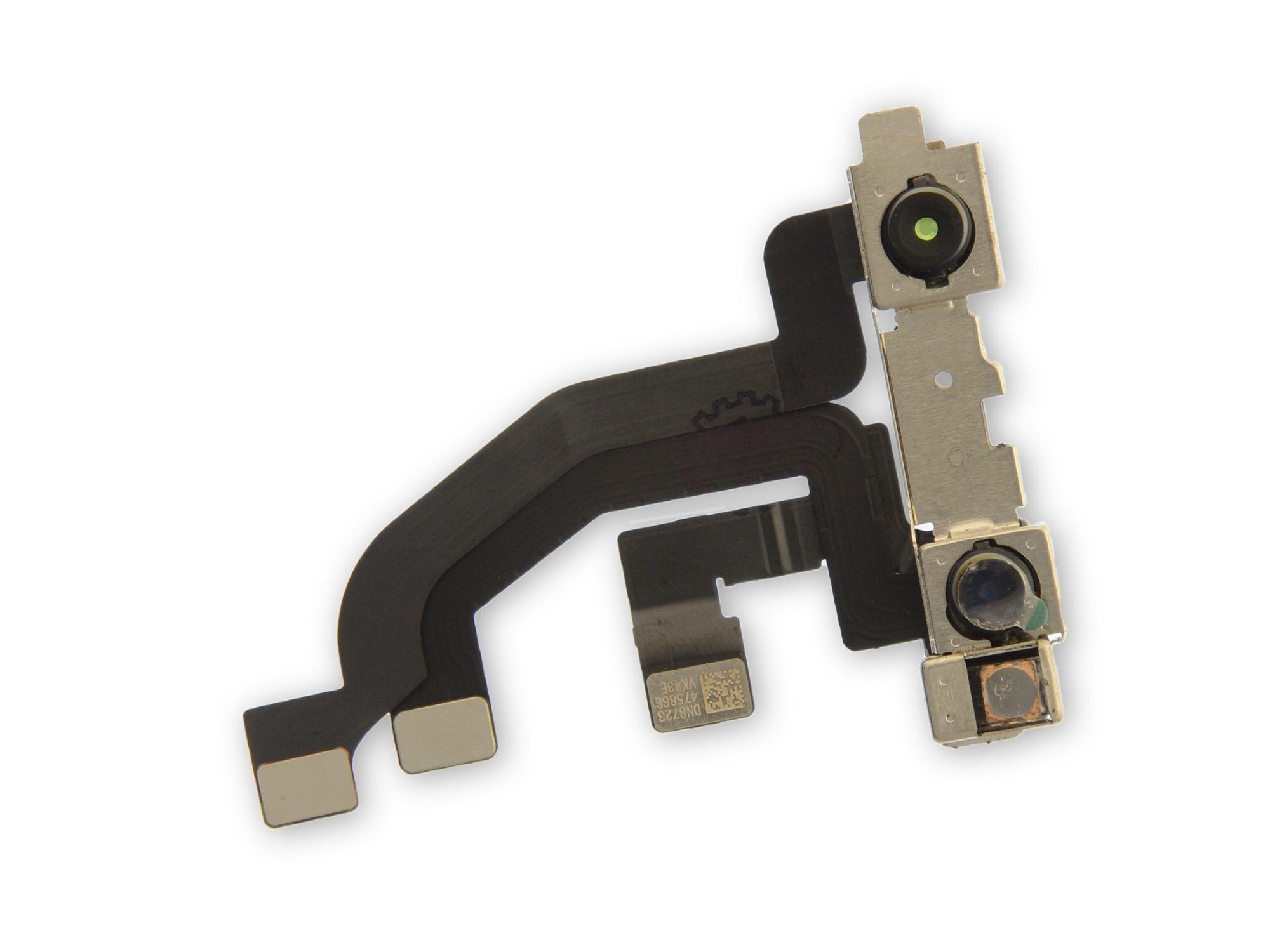
– Now, it’s time to disconnect the front camera connector. Take it slow and steady, you’ve got this!
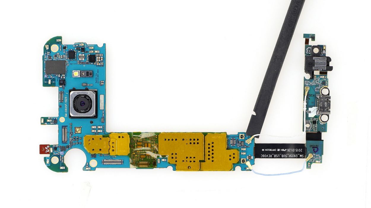
Step 5
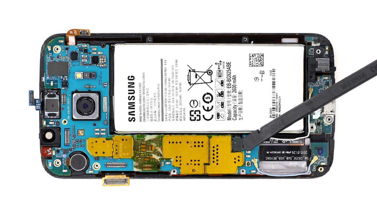
Hey there! Just a heads up: there’s a tiny plastic pin hanging out in the SIM tray opening. Keep an eye on it so it doesn’t take a little tumble!
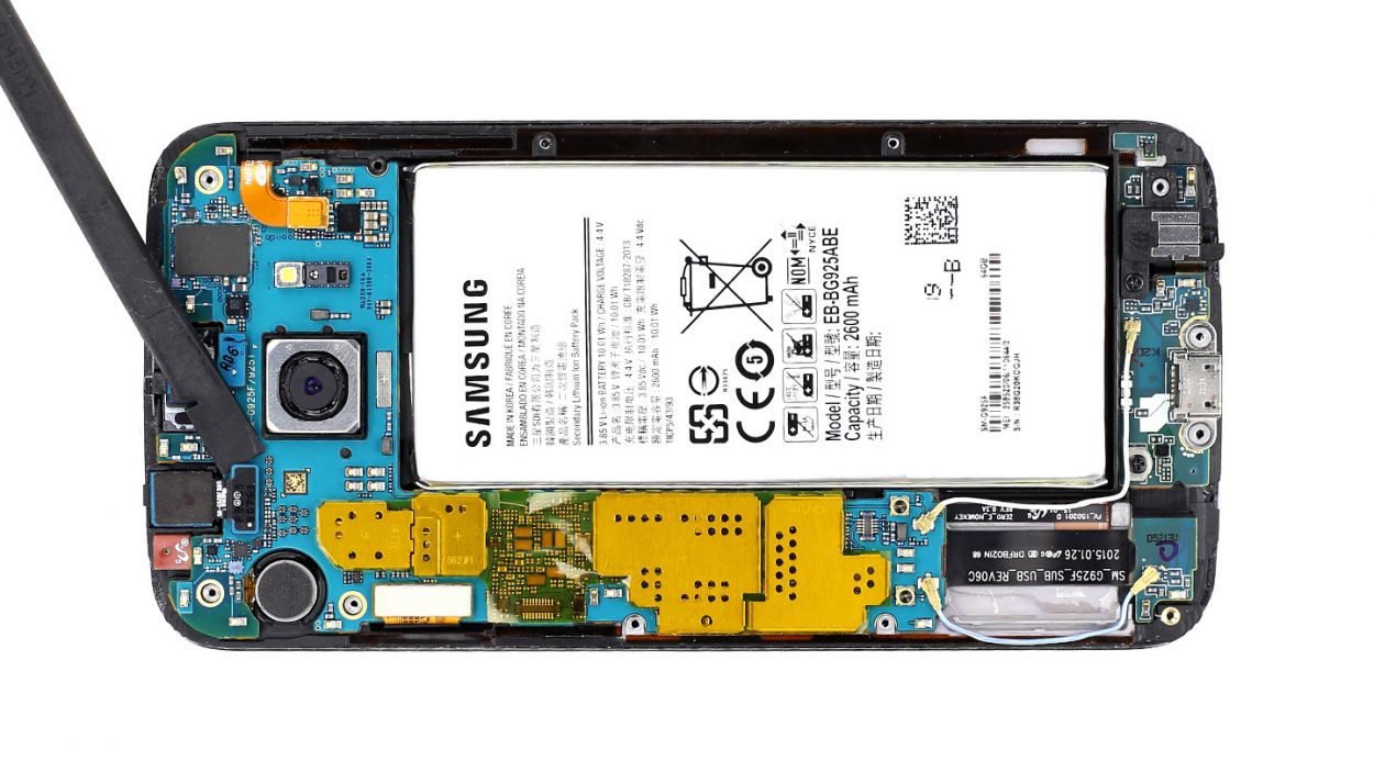
– Alright, let’s get those connectors unplugged! Gently slide the spudger’s tip under each one and give them a little lift. We’re talking battery, display (don’t forget to hook up the new display and test everything!), earpiece, home button, and both antenna connectors.
– Now, for a bit of spudger magic! Slide it under the logic board near the antenna connectors and carefully disconnect the dock connector cable underneath.
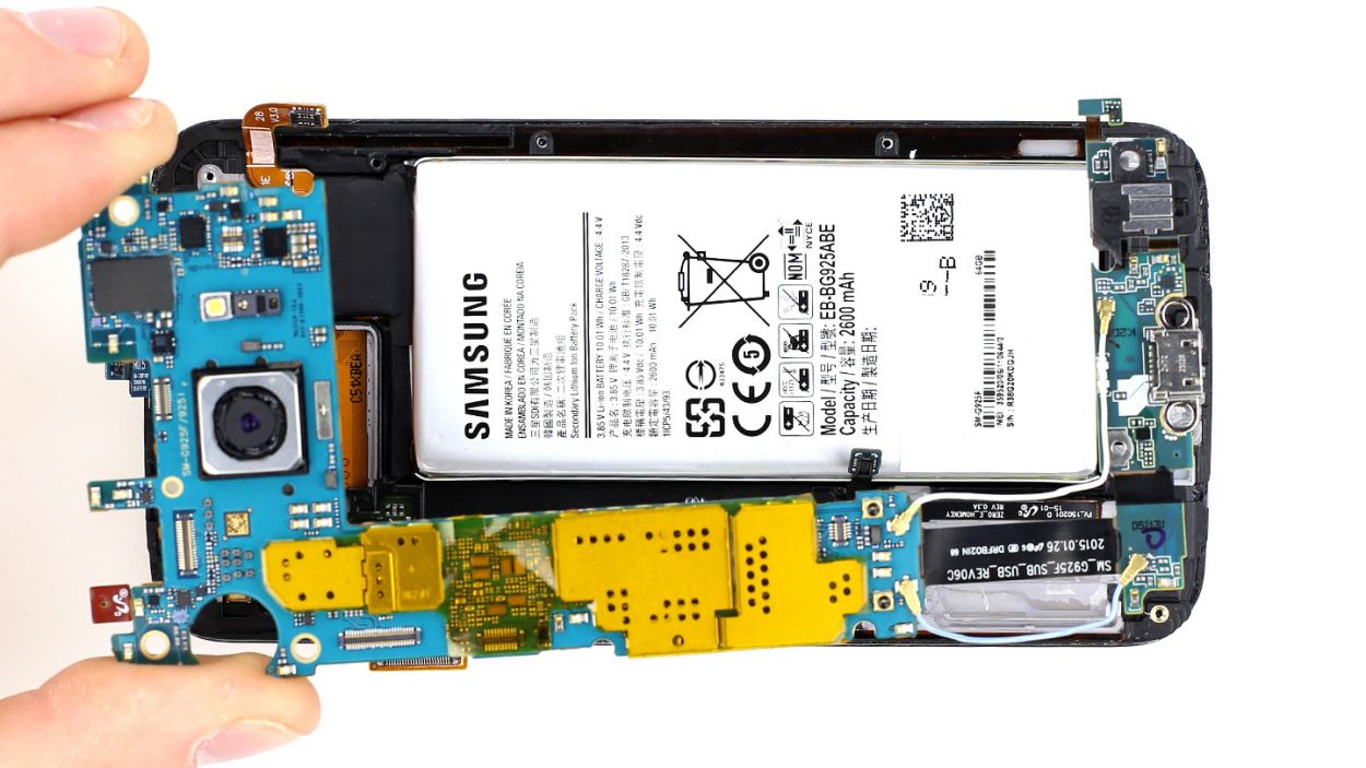
– Time to free that logic board! It’s your moment to shine. If you need a hand, you can always schedule a repair.
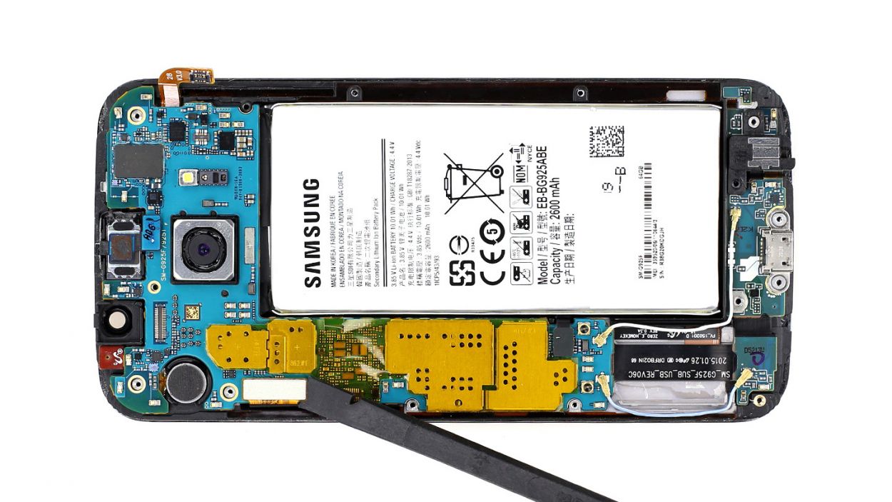
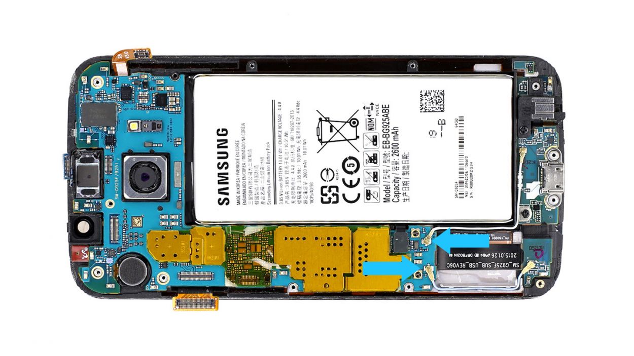
Step 6
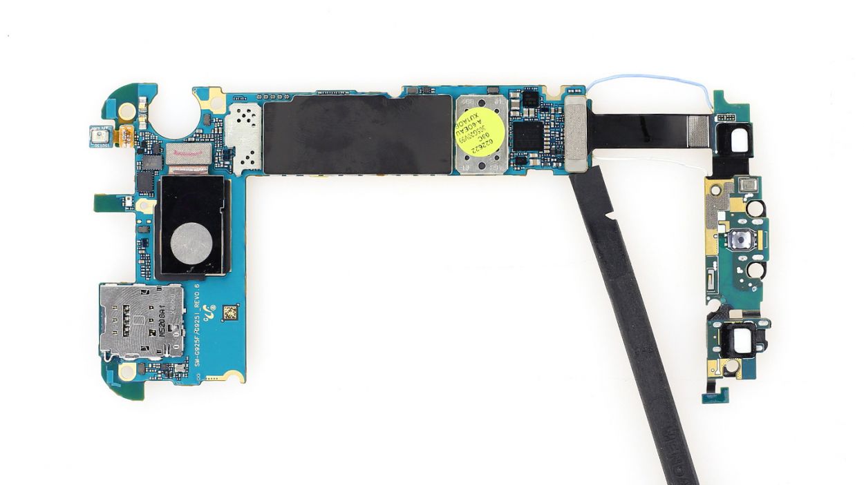
– First up, let’s disconnect those two antenna cables. Gently slide the flat end of the spudger just below the contacts and give them a little lift.
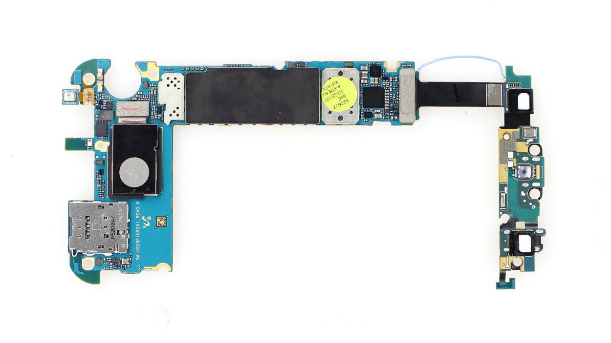
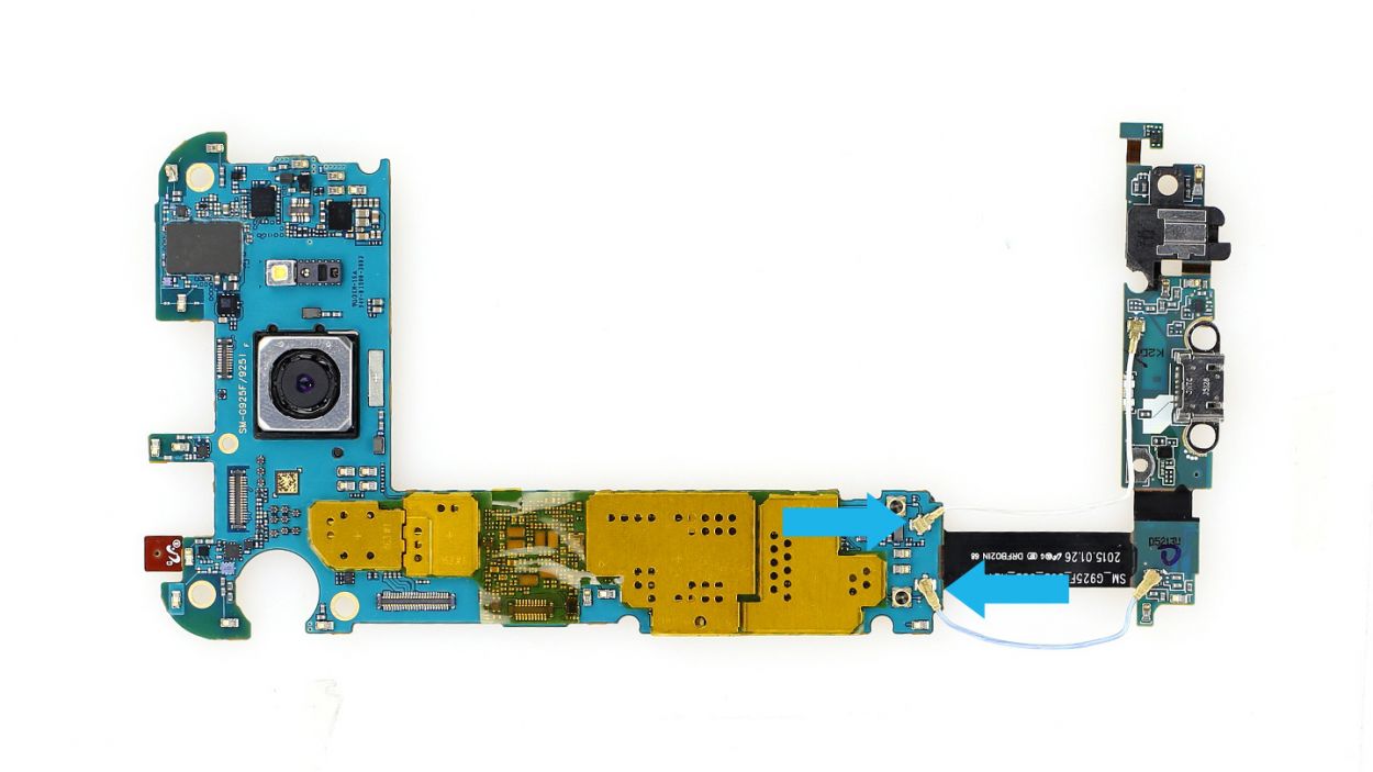
– Next, flip that logic board around! It’s time to disconnect the USB connector cable on the back. Use the flat end of the spudger to carefully pop that connector off.
– Now, it’s time for the grand re-connection! Hook up the new USB connector to the logic board. And hey, don’t forget to reattach those antenna connectors!
Step 7
– Reconnect the dock connector cable set and those two antenna cables to the logic board like a pro! Then, gently place it back into the frame.
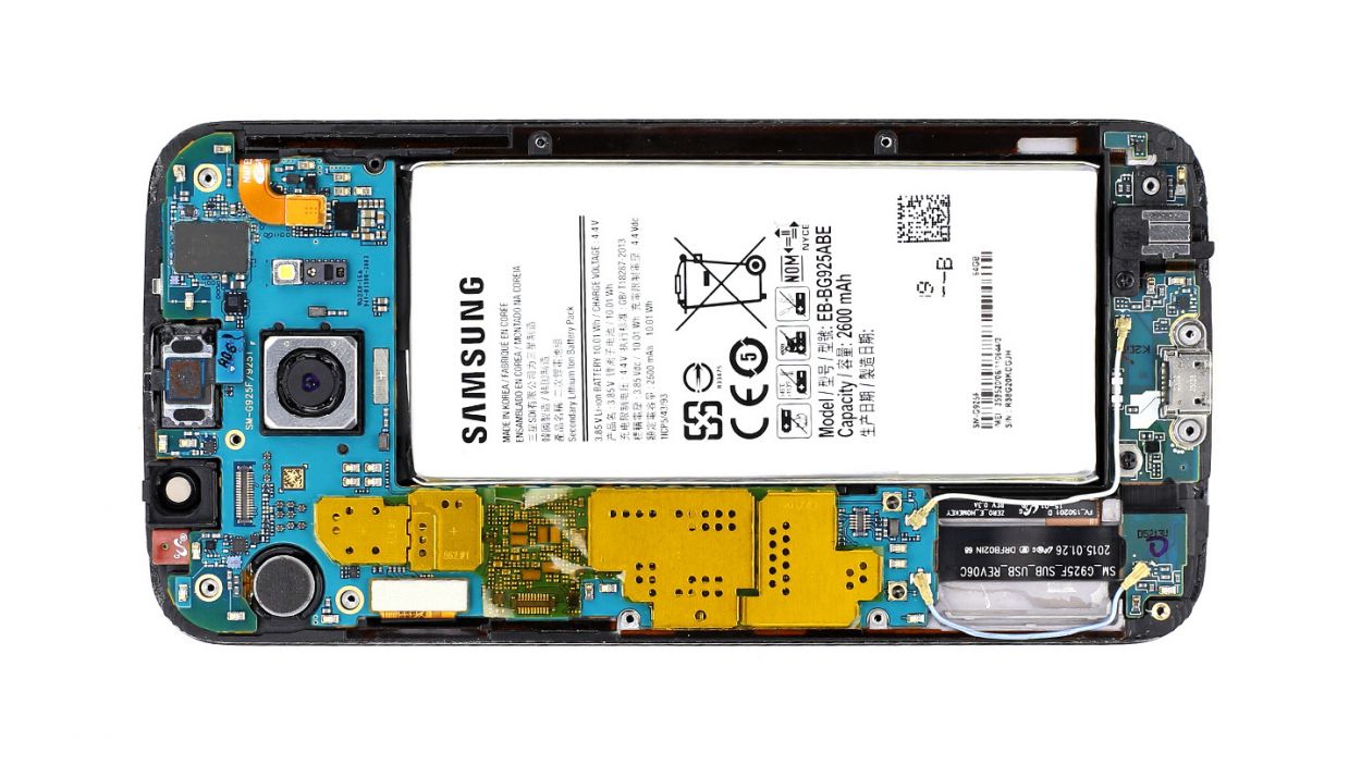
– Once everything is snug and secure, it’s time to add the rest of the logic board. Just keep an eye on those cables – they should stay out from under the logic board. Check the picture to make sure your logic board is sitting just right.
– Now, let’s bring all the connectors back to life: Battery, Display, Earpiece, and Home button – reconnect them all!
Step 8
– Time to place the front camera back where it belongs!
– Next up, let’s connect that little guy to the logic board.
Step 9


– Let’s get that outer frame back on the main component! Start at the dock connector and give those two frame pieces a good press together.
– Now, it’s time to secure them with some screws. Grab your 13 x 3.3 mm Phillips screws and tighten them up!
Step 10
– Alright, it’s time for the final touch! Get that back cover ready to go.
– Don’t worry, the old glue is still holding on like a champ.
– Carefully place the back cover back on, give it a gentle warm-up, and then with a little bit of elbow grease, press it down onto the smartphone for a moment. You’ve got this!