DIY Guide: Replace USB-C Port on OnePlus 6
Duration: 90 min.
Steps: 20 Steps
Is your OnePlus 6 giving you charging troubles? It might be time to check that USB-C port—could be a little defective! Swapping it out will bring back your quick charge and file transfer magic. Just a heads up, getting into the OnePlus 6 means tackling that glass back cover, so it’s a bit of a challenge. Before diving in, make sure the USB port isn’t just a little dirty, which could be why your cable isn’t fitting snugly. And hey, don’t forget to back up your data, clear off a nice workspace, and take your time with this. If you hit any snags, feel free to reach out through our live chat or drop a comment. If you need help, you can always schedule a repair!
Step 1

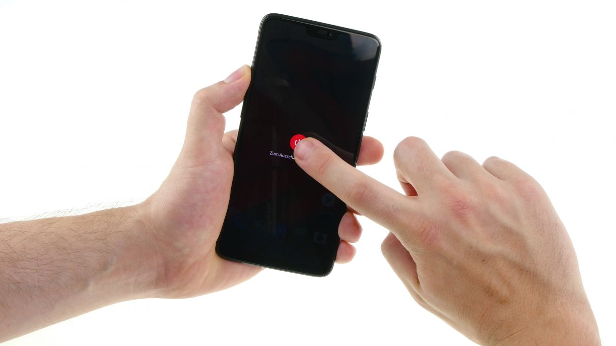
– Hold down that power button until you see ‘Turn off’. Easy peasy!
– Tap it again to confirm. You got this!
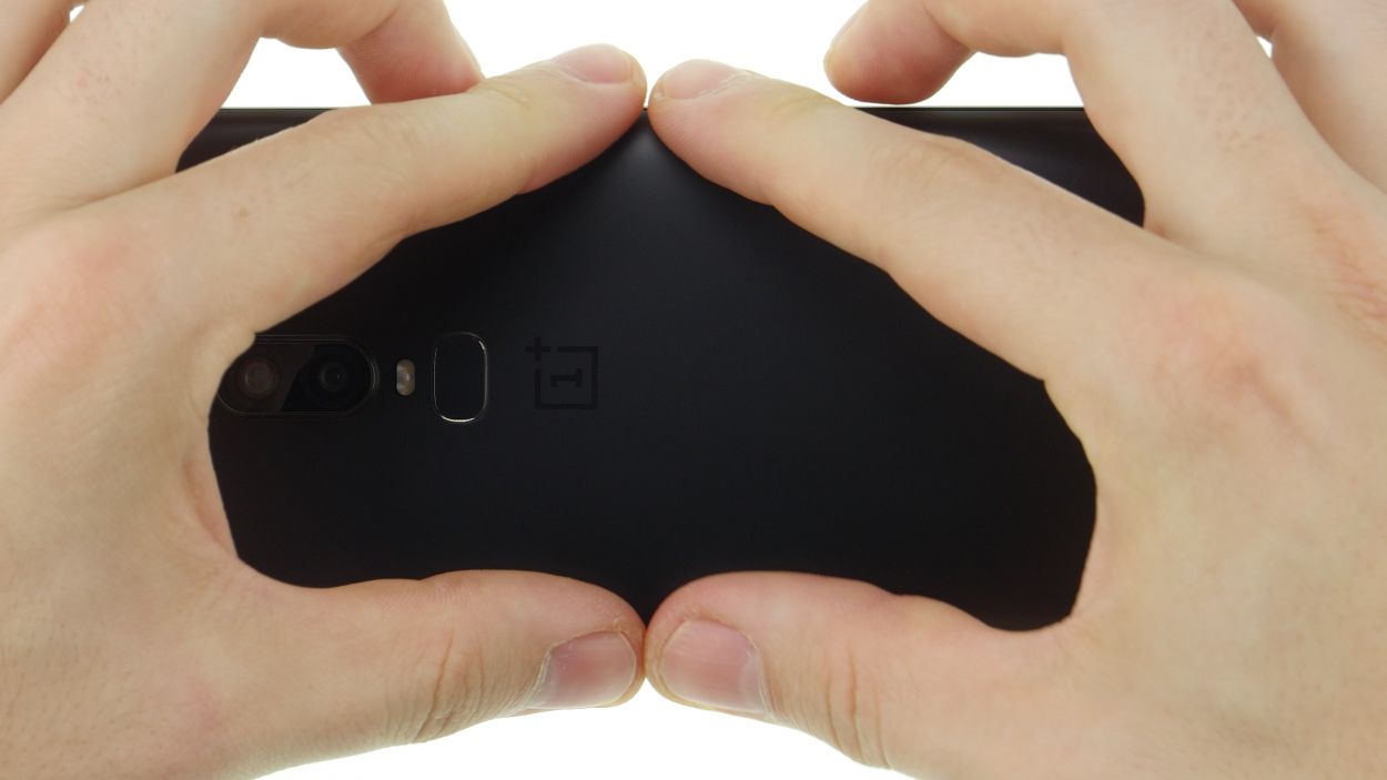
Step 2
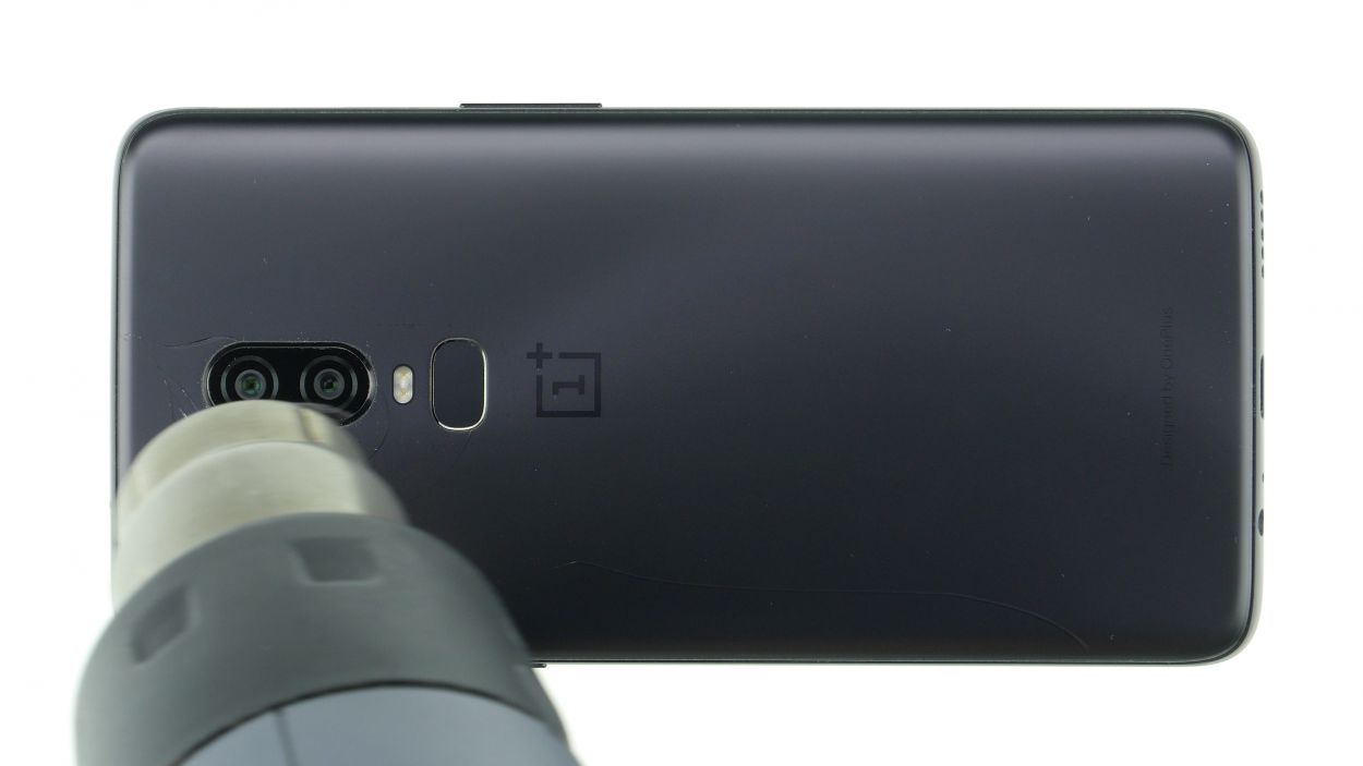
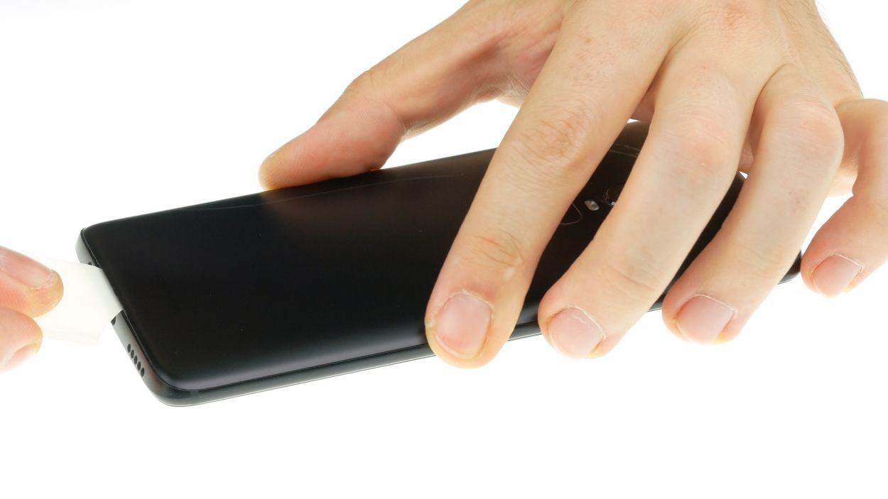
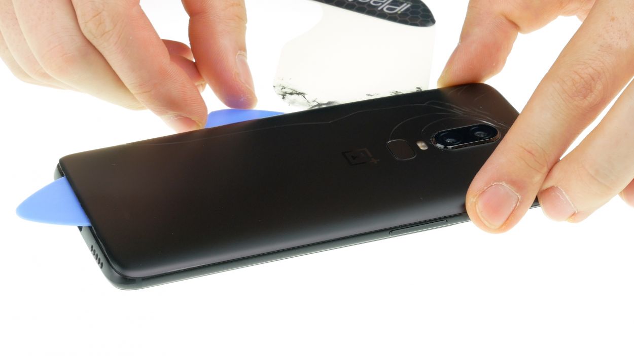
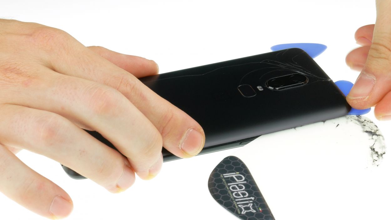
– Warm up the area where you’re starting.
– Slide a flat tool between the back cover and the frame.
Hey there, champ! This back cover is a bit of a diva, so let’s be gentle. Apply some heat, take your time (maybe grab a coffee!), and remember, patience is key. It might take up to 30 minutes, but you’ve got this! If you’re feeling unsure, you can always schedule a repair.
The iPlastix is made of plastic, so it won’t scratch your device. However, it’s super soft and can be a bit tricky to insert. If you need help, you can always schedule a repair.
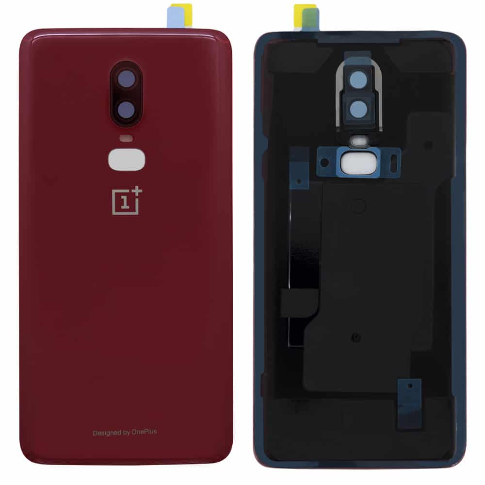
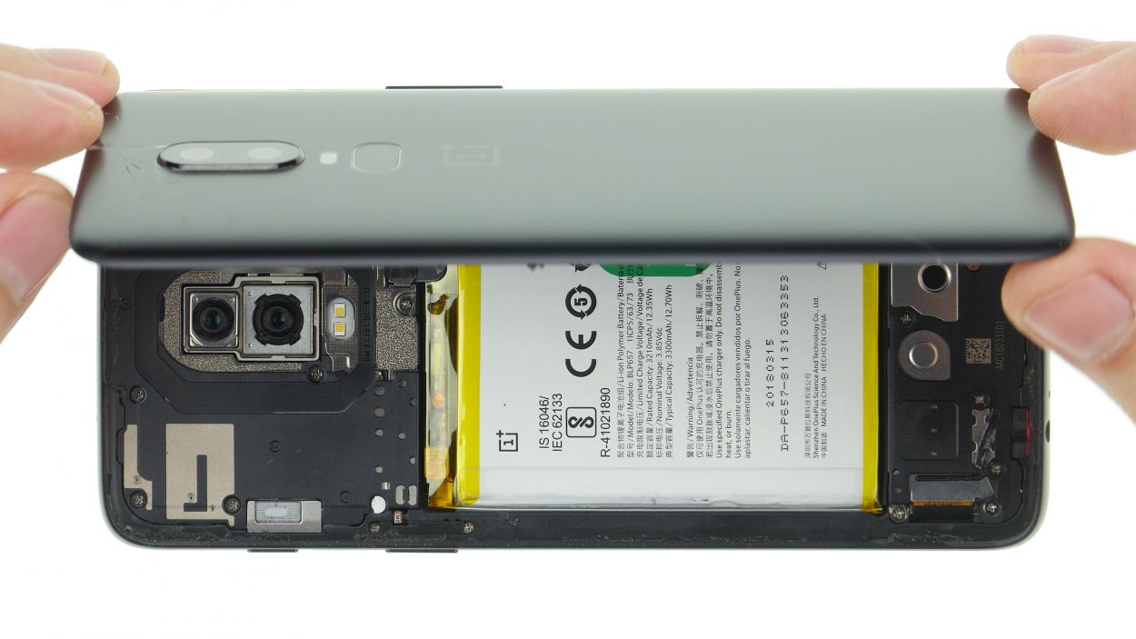
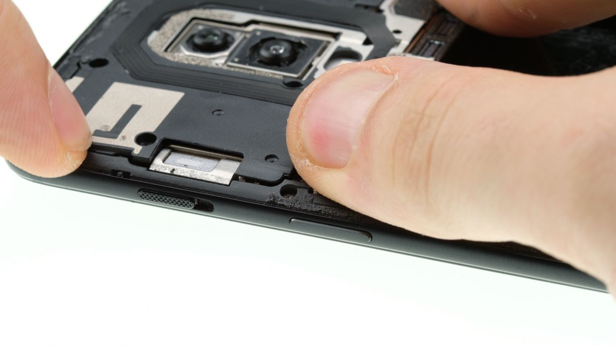
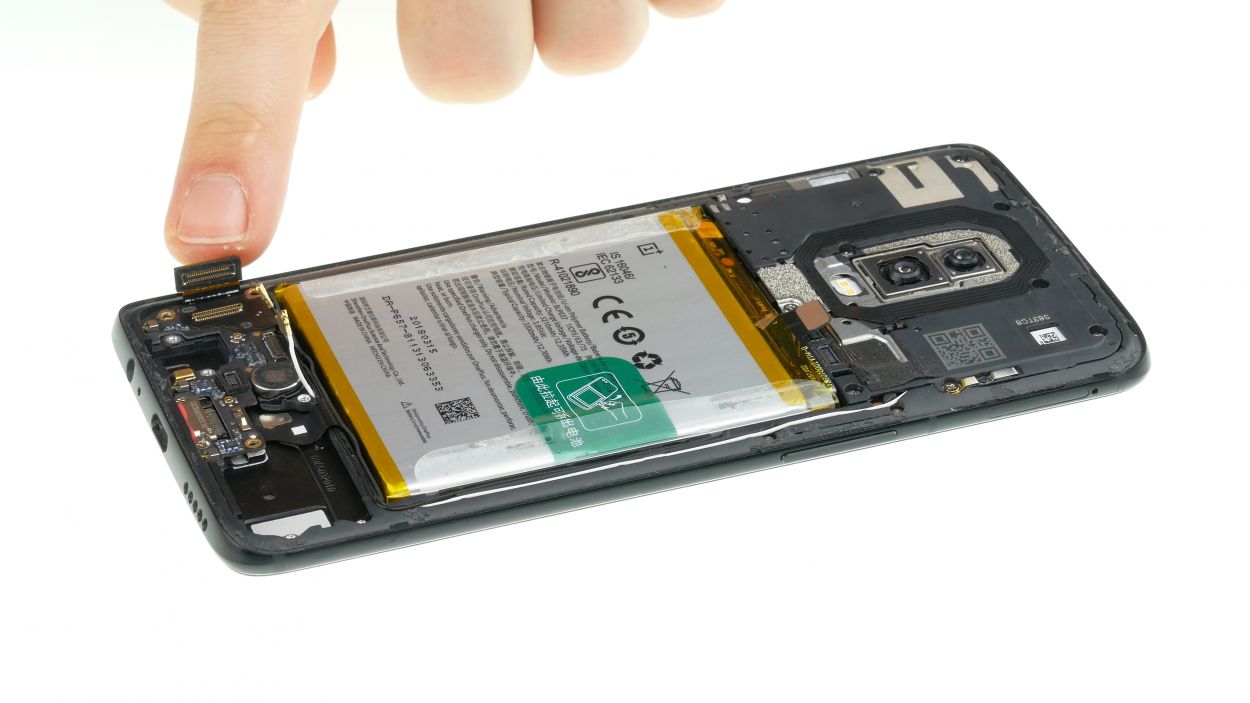
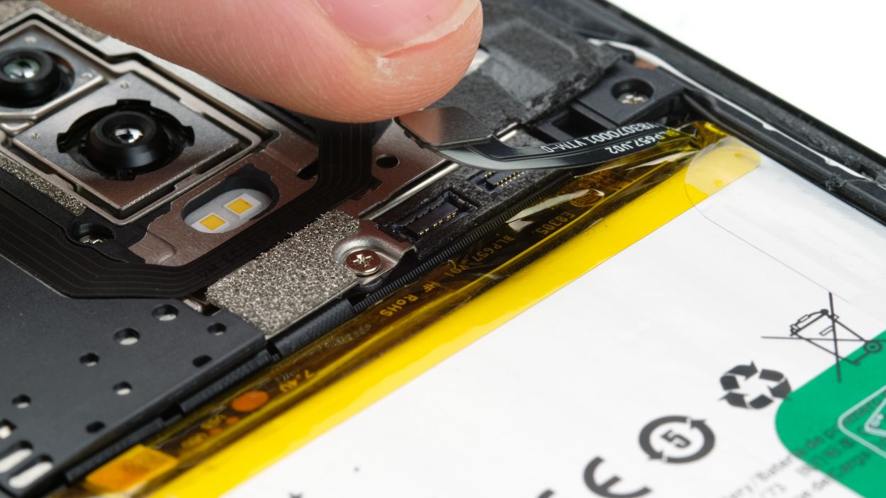
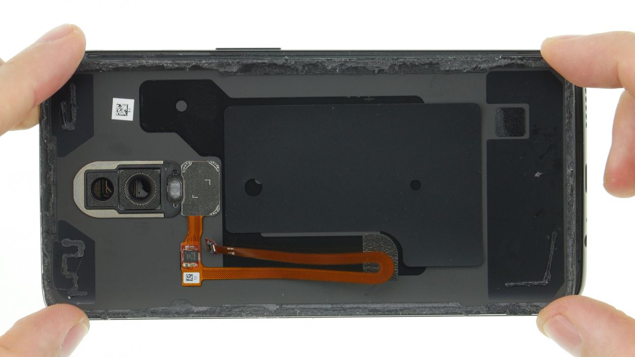
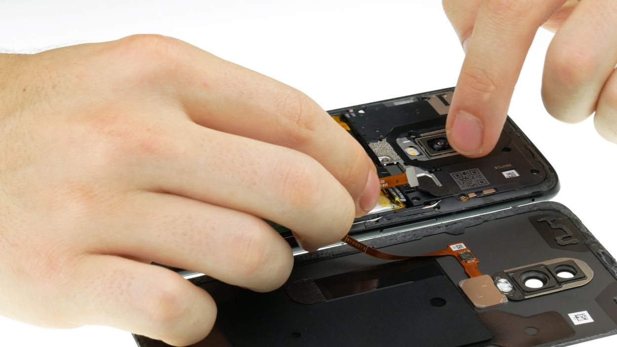
Step 3
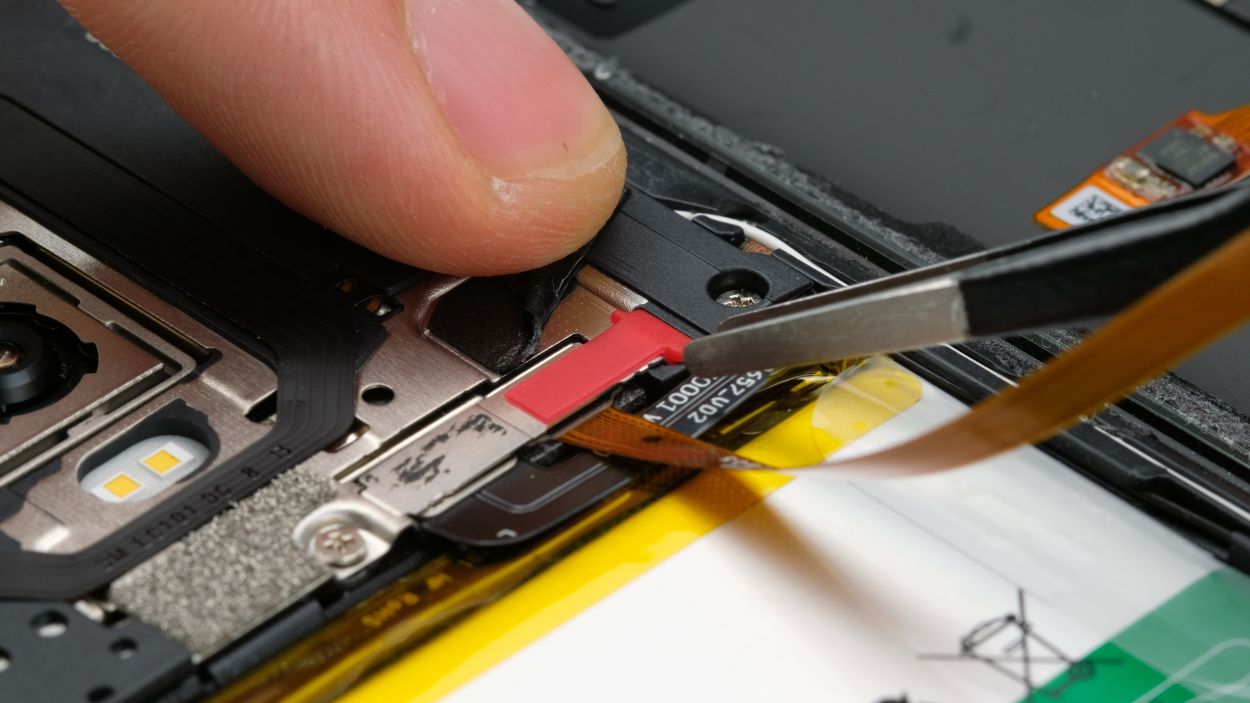
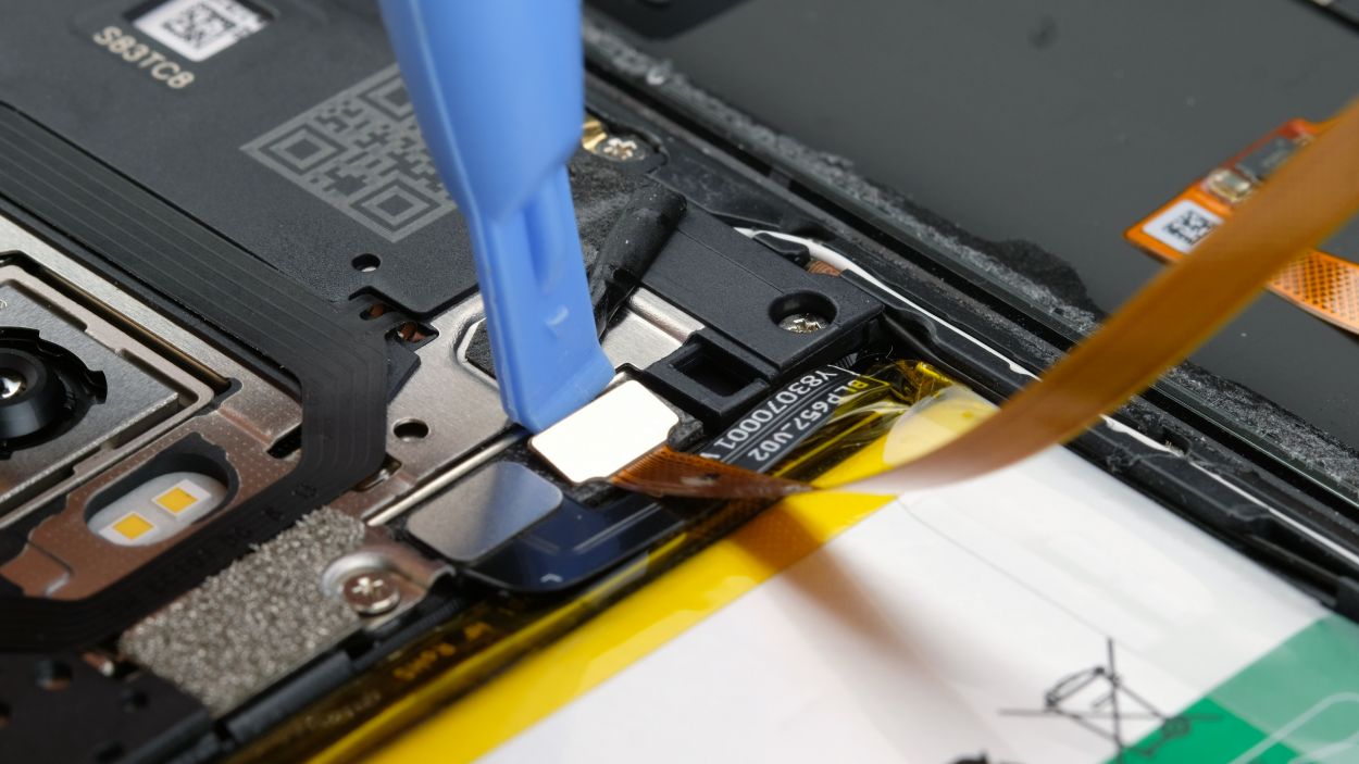
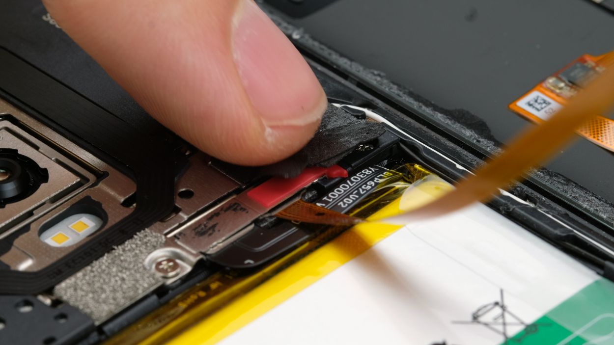
Fingerprint Connector
– Alright, gently lift up that loosened back cover and flip it over.
– Peel off the adhesive strip over the cover plate.
– Use tweezers or your fingers to take off the cover over the connector.
– Now, carefully disconnect the connector with a spudger or your fingernail and remove the back cover. If you need help, you can always schedule a repair.
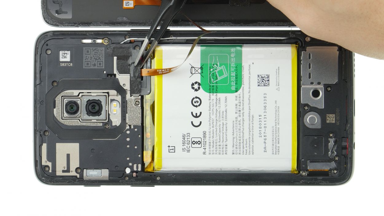
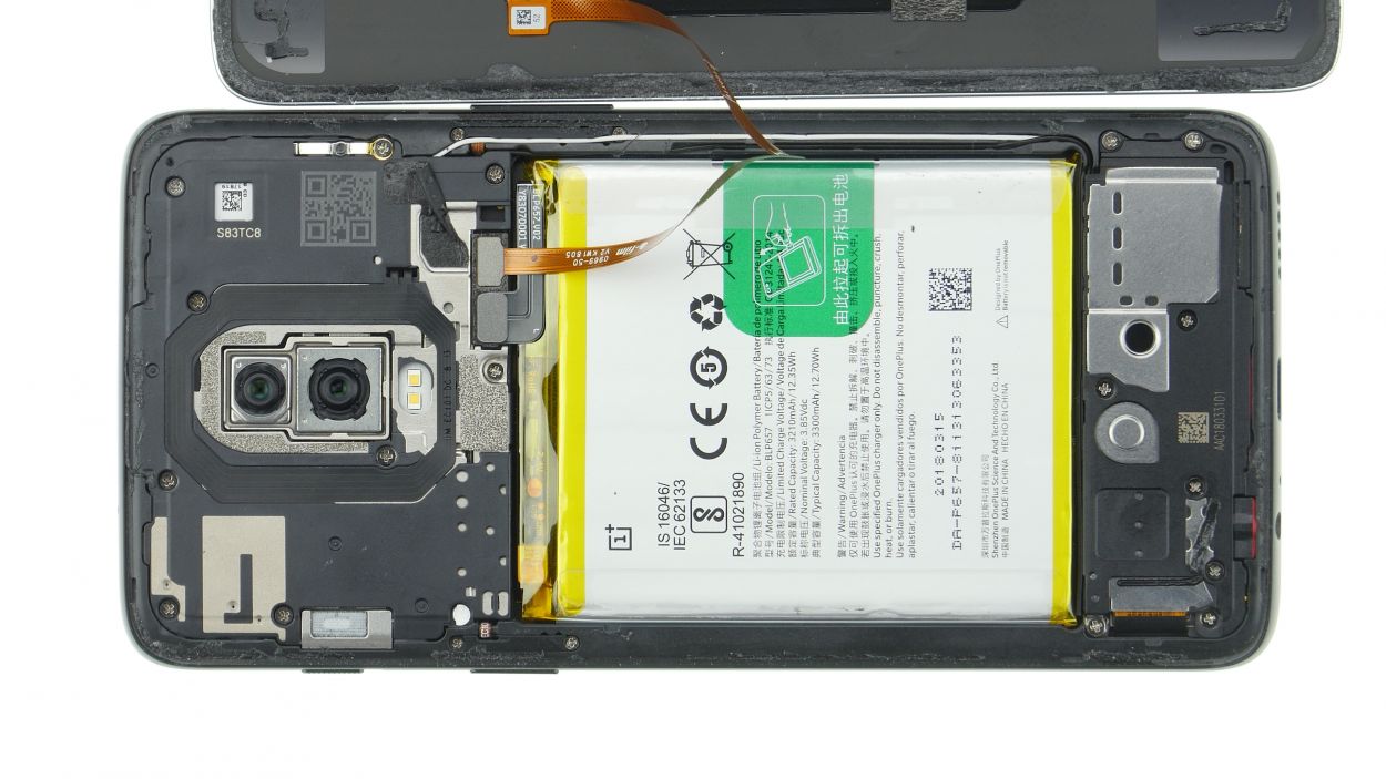
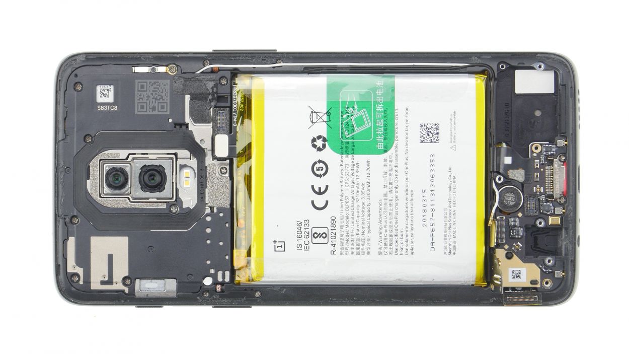
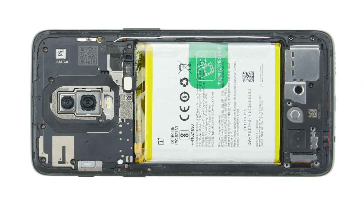
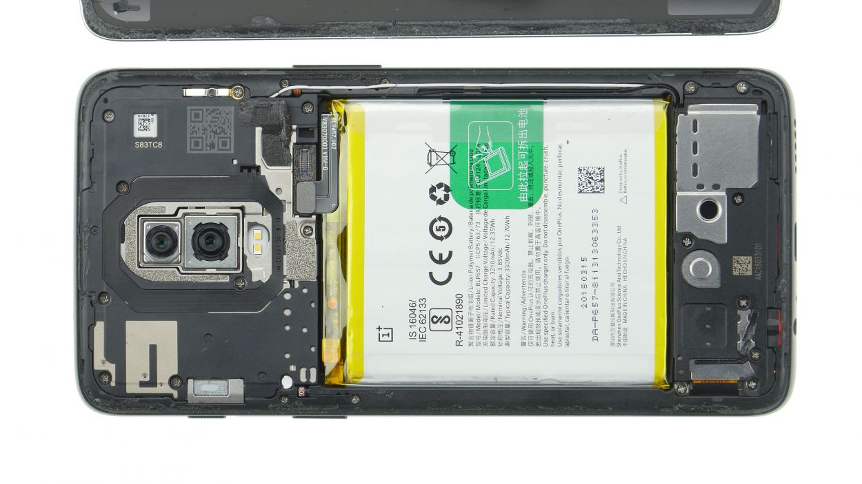
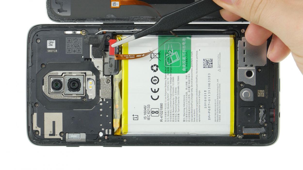
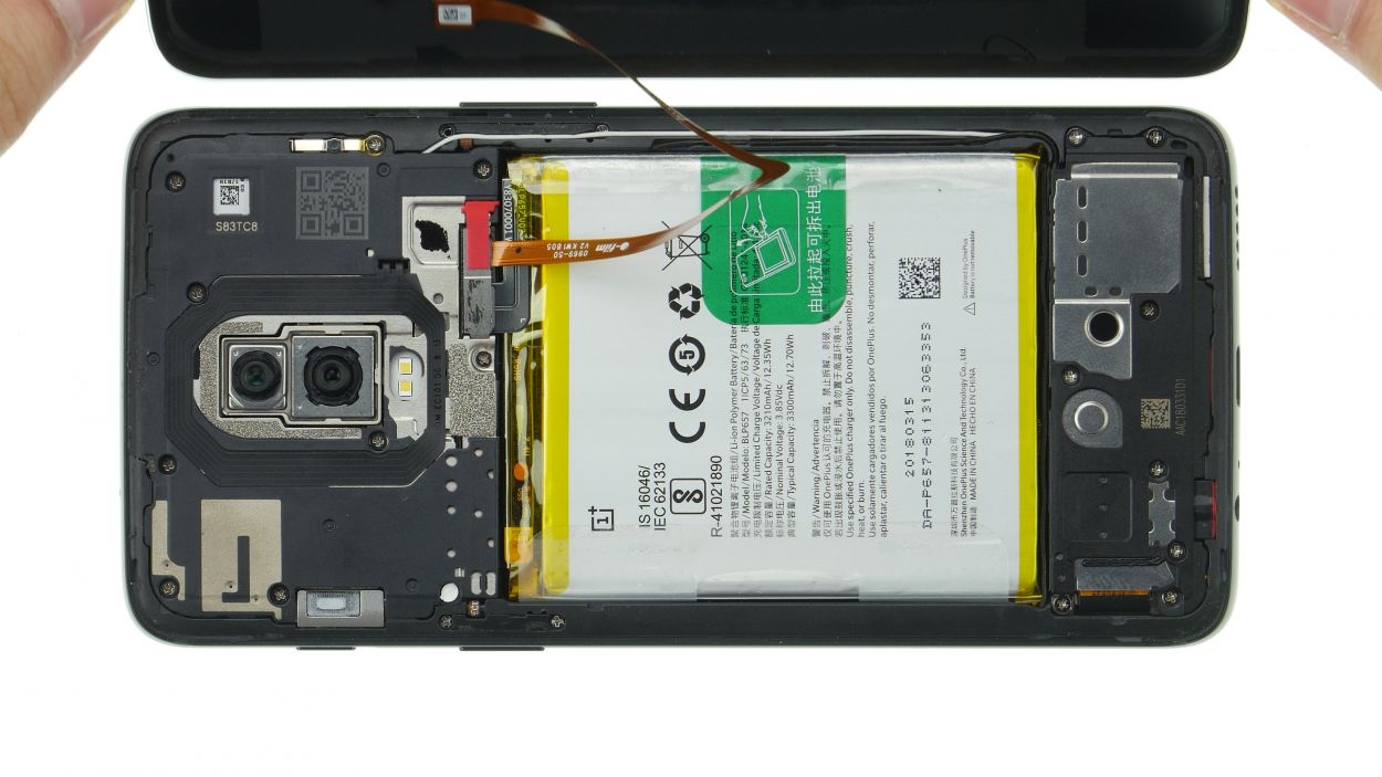
Step 4
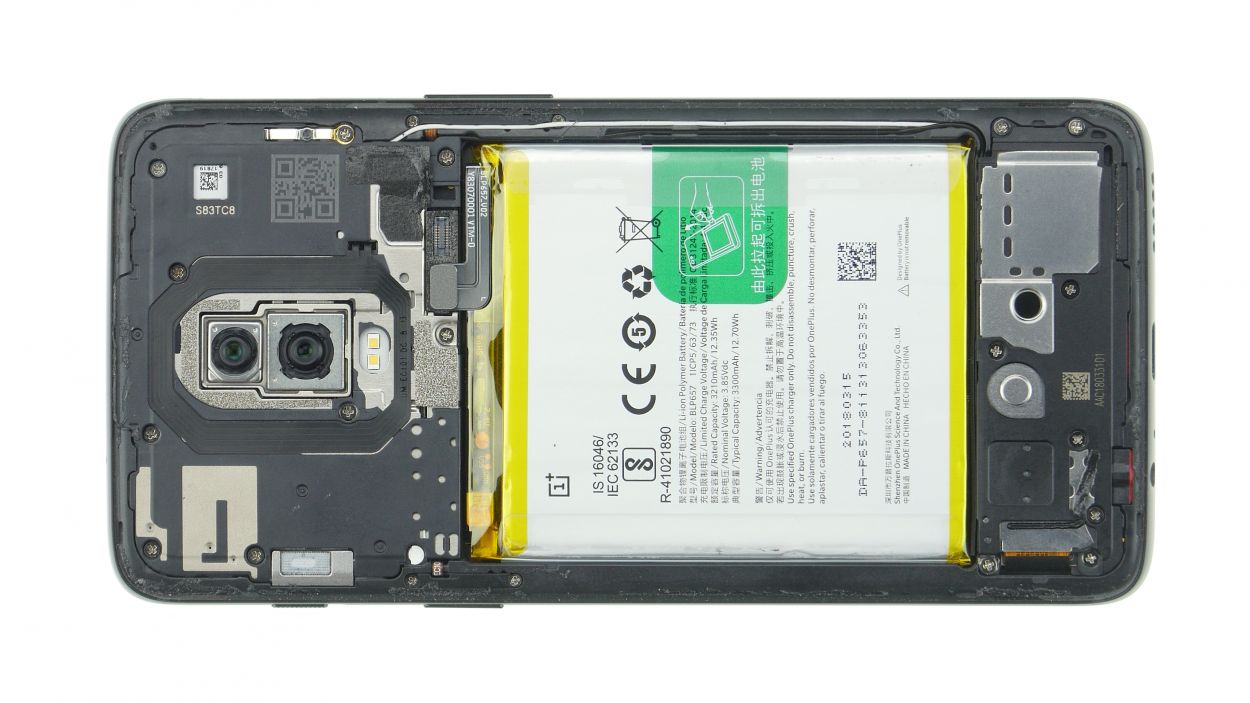
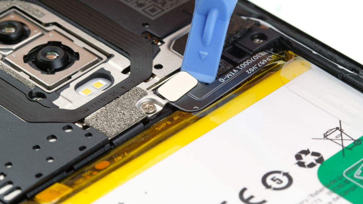
Battery Connector
– Alright, the battery connector is free!
– Unplug the battery to avoid any short circuits during the repair. If you need help, you can always schedule a repair.
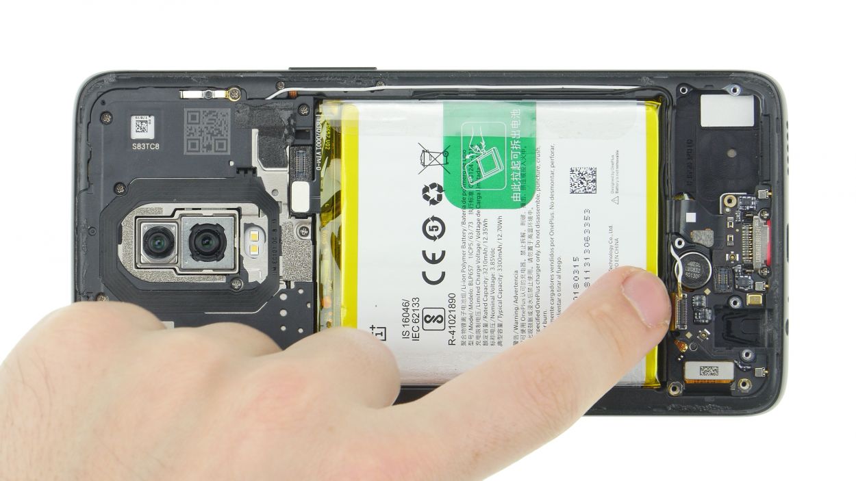
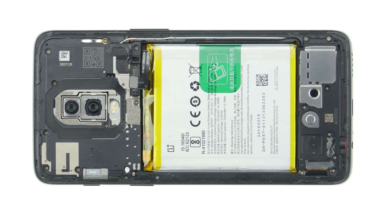
Step 5
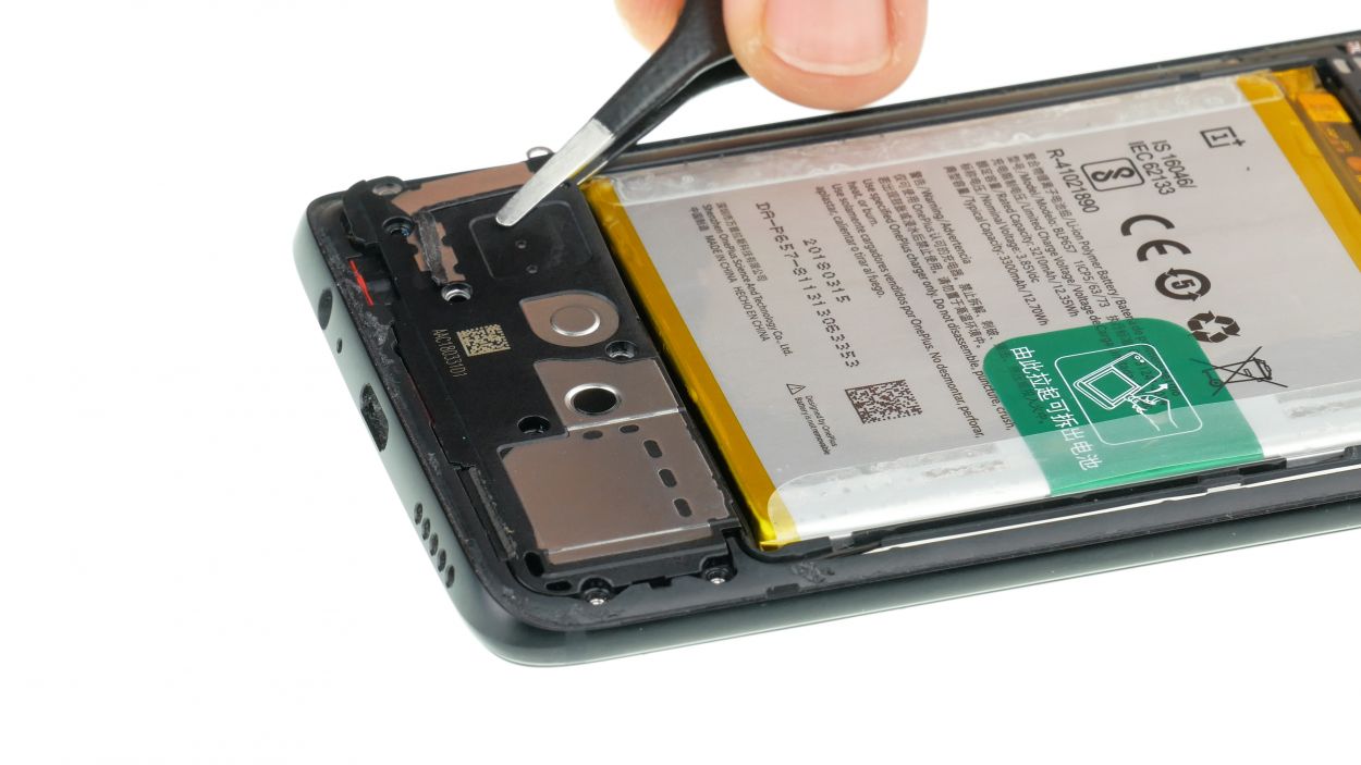
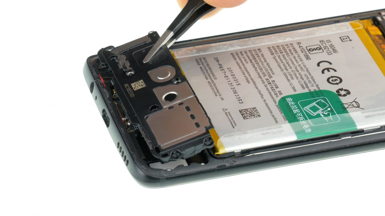
8 × 3,0 mm Phillips
– Alright, let’s get those marked screws loose and outta there!
– Next, grab your tweezers and carefully remove the cover. The speaker’s chillin’ in the cover.
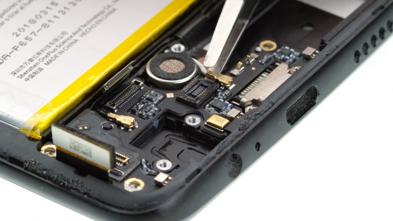
Step 6
– Gently loosen the headphone jack connector with a spudger.
– Now, go ahead and remove the headphone jack using tweezers. If you need help, you can always schedule a repair.
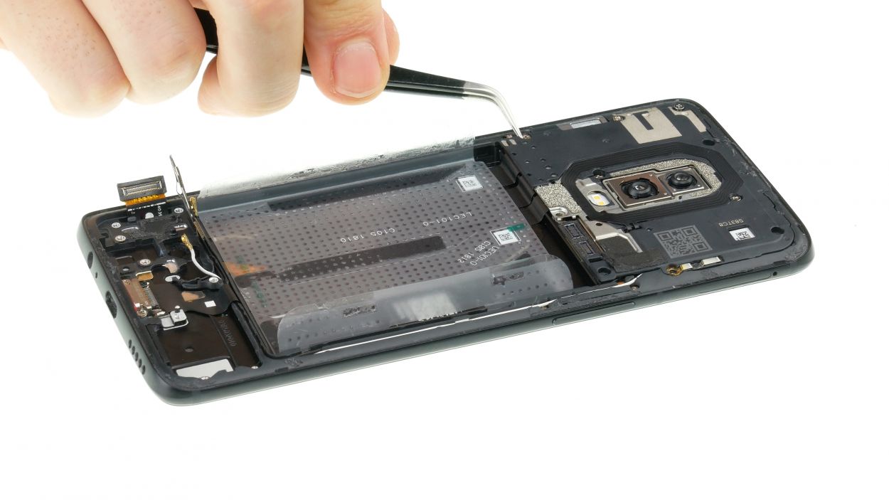
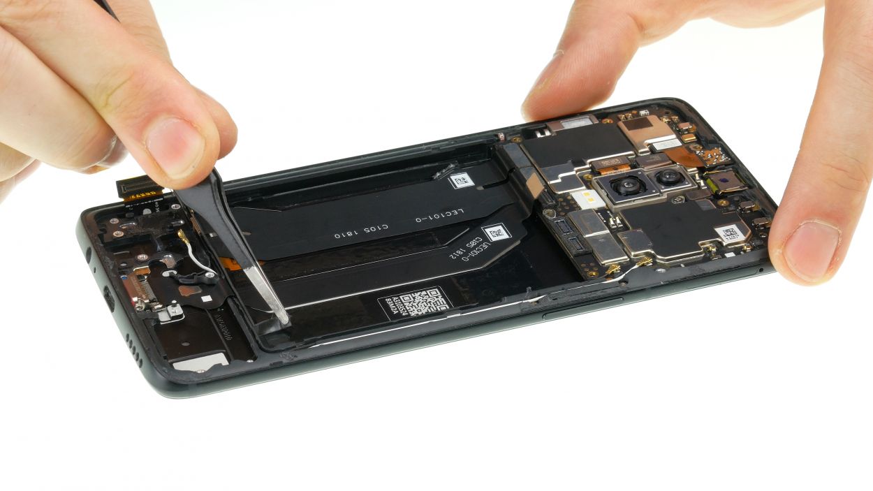
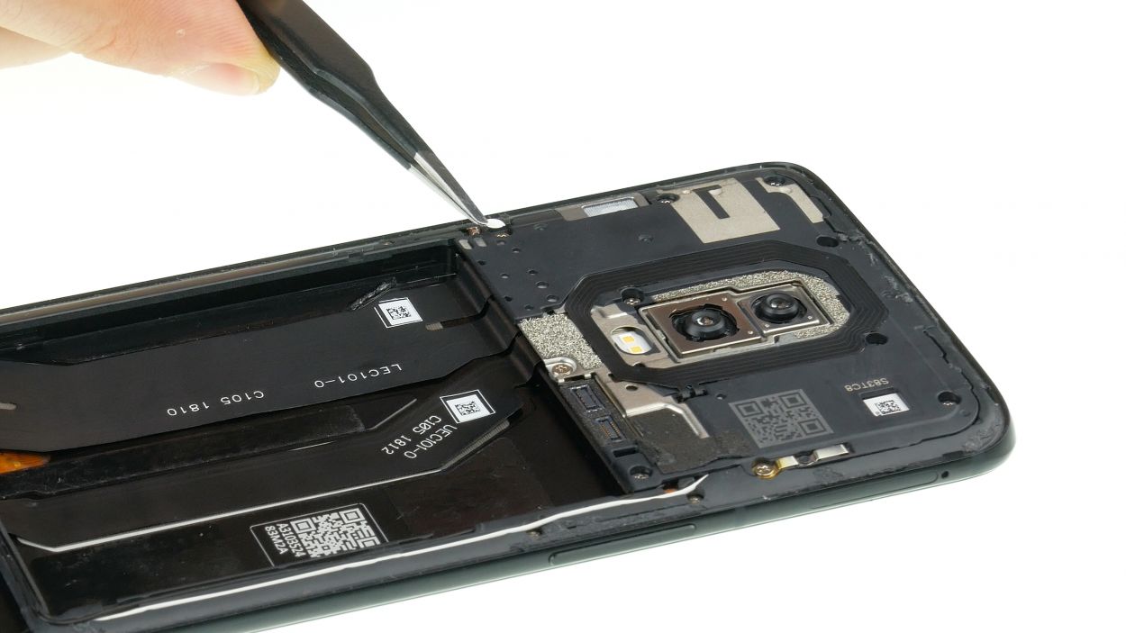
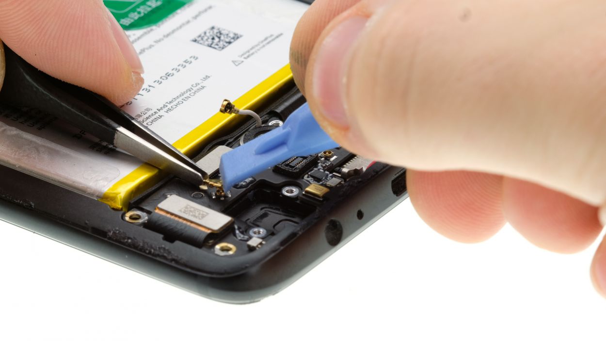
Step 7

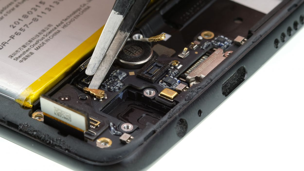
Gently twist the tweezers to separate the antennas. Be careful not to mess up the sockets on the board. If you need help, you can always schedule a repair.
– Gently loosen the connectors for the display and main board using a spudger. Easy does it!
– Next, carefully disconnect the antenna cables from the marked slots. You’re doing great!
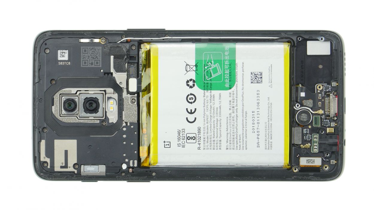
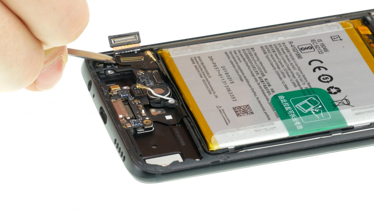
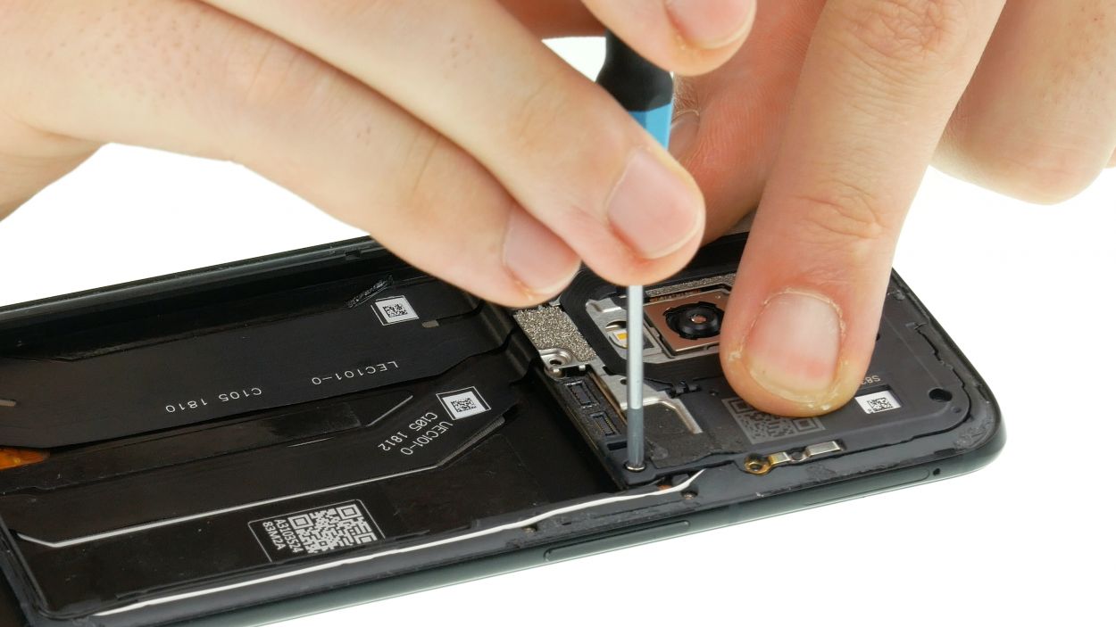
Step 8
Step 9
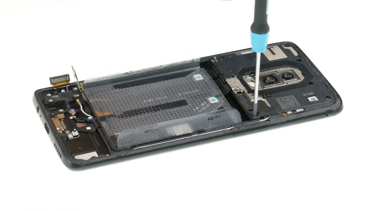
10 × 3,0 mm Phillips
If those pesky screws decide to play hard to get, grab a trusty pair of tweezers and give them a gentle nudge to set them free!
– Carefully remove the moisture indicator to reattach it later.
– Loosen the Phillips screws.
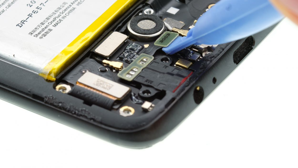
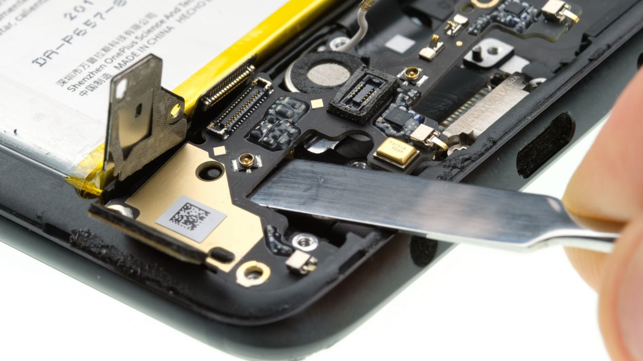
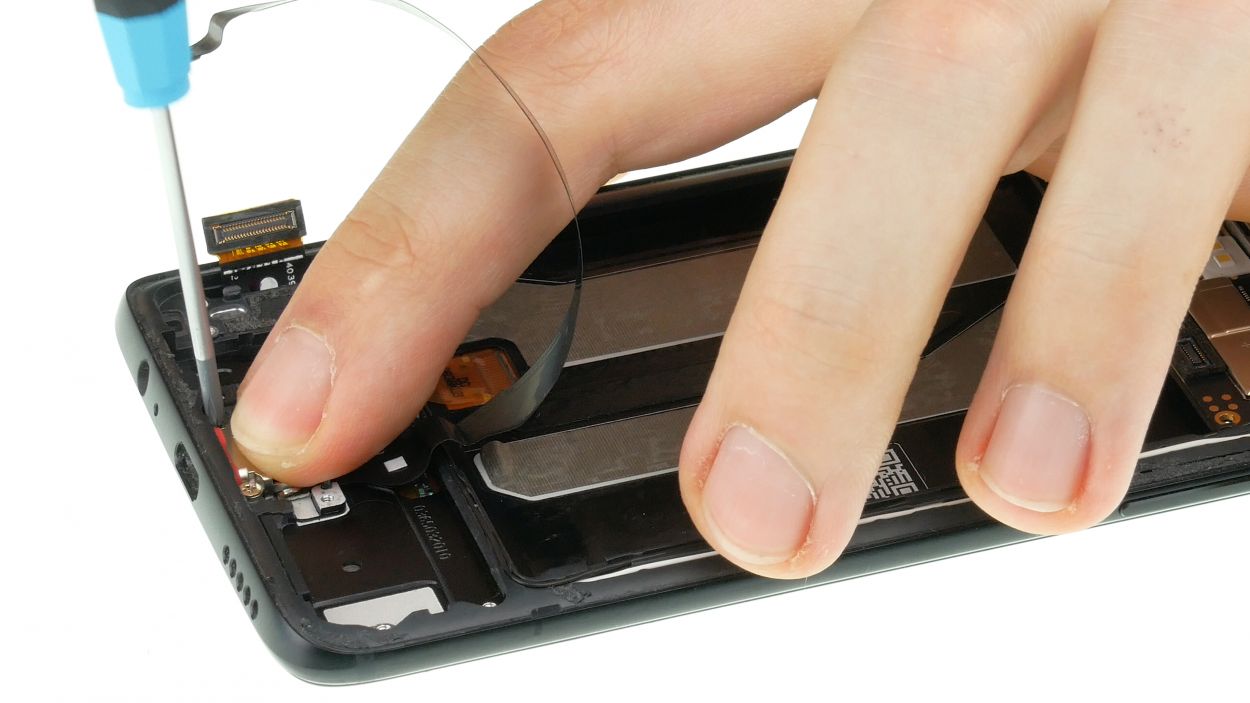
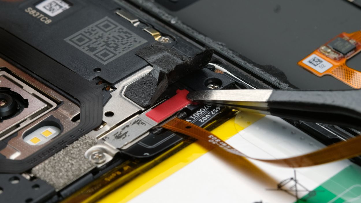
Step 10
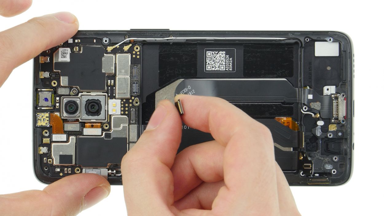
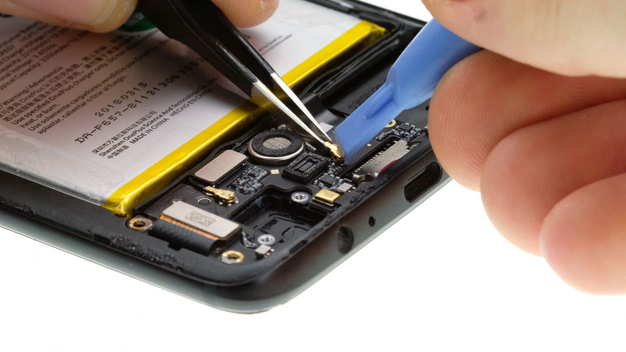
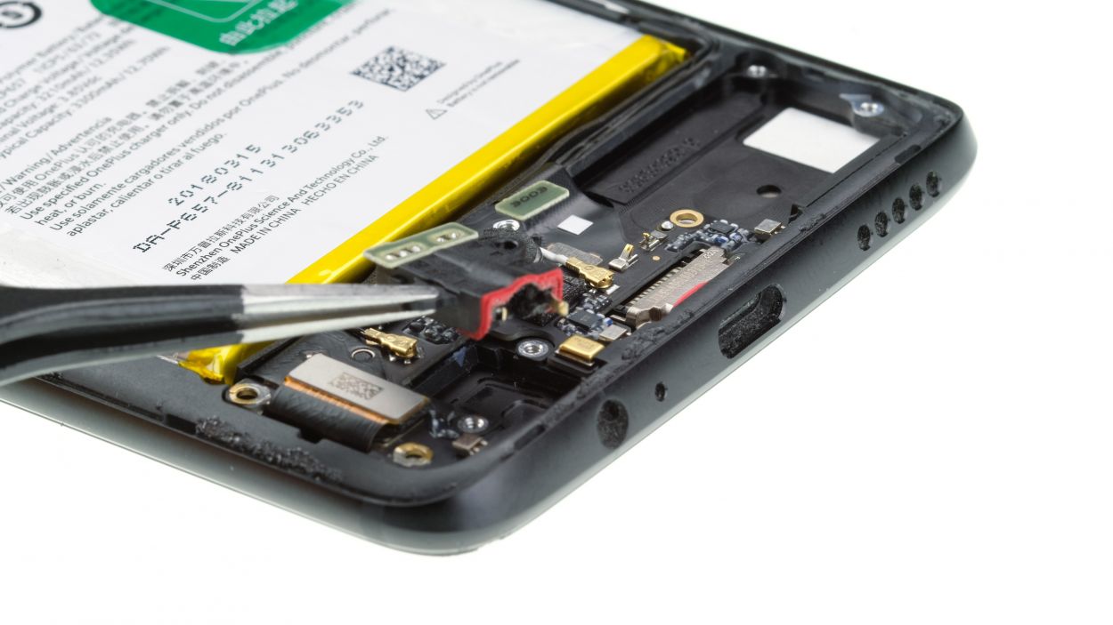
2 × 2,4 mm Phillips
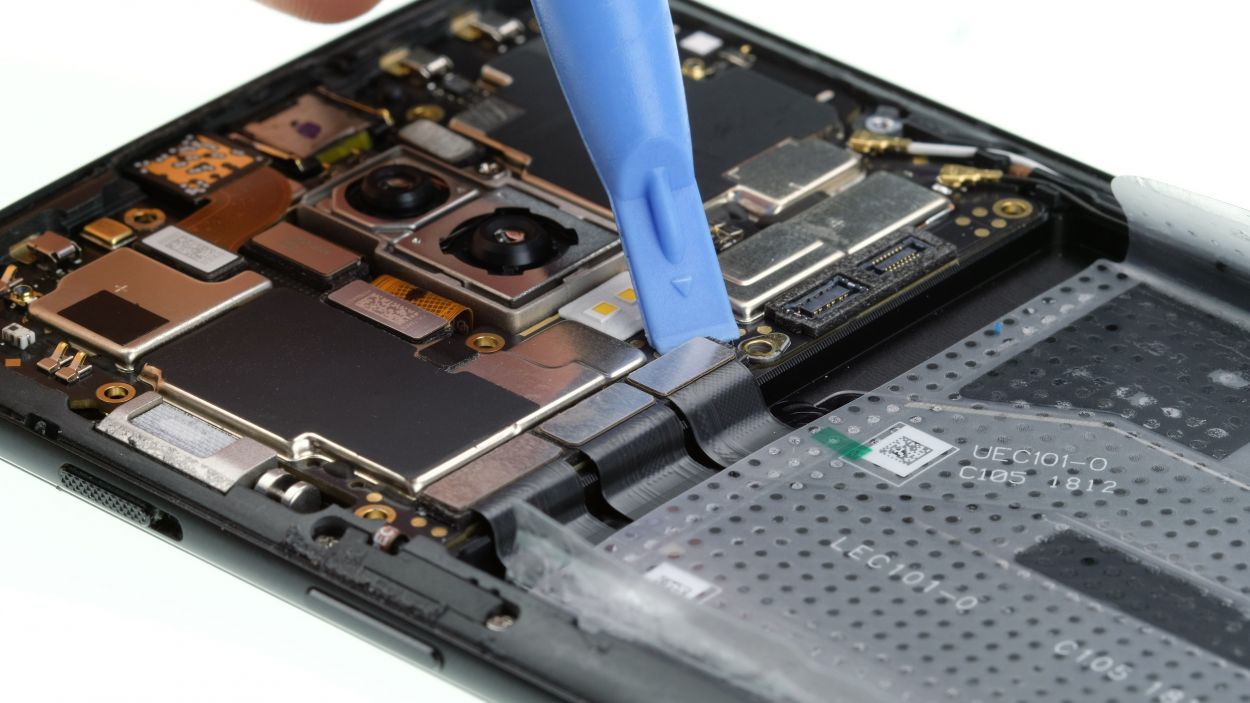
USB-Flex Connector
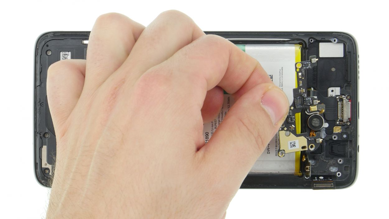
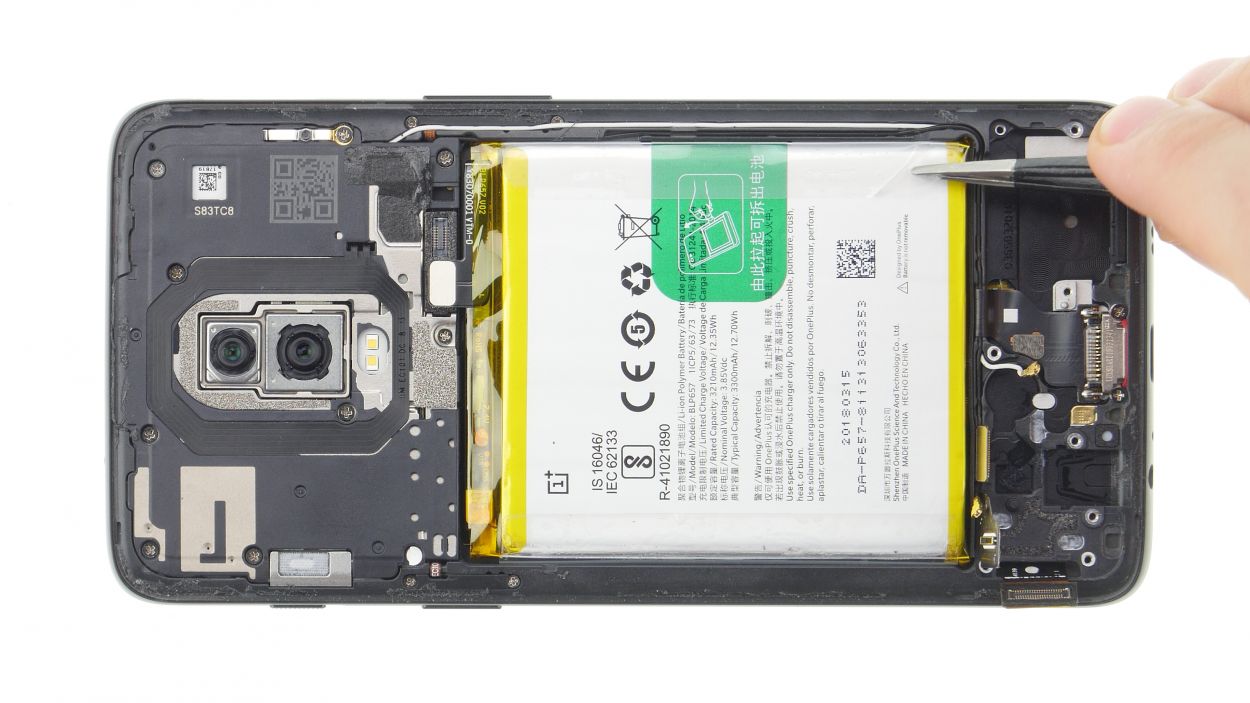
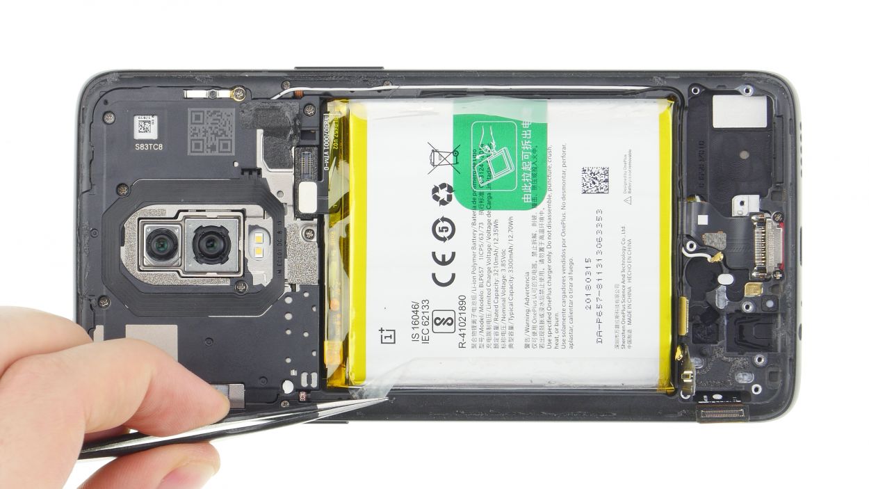
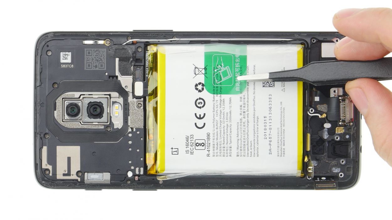
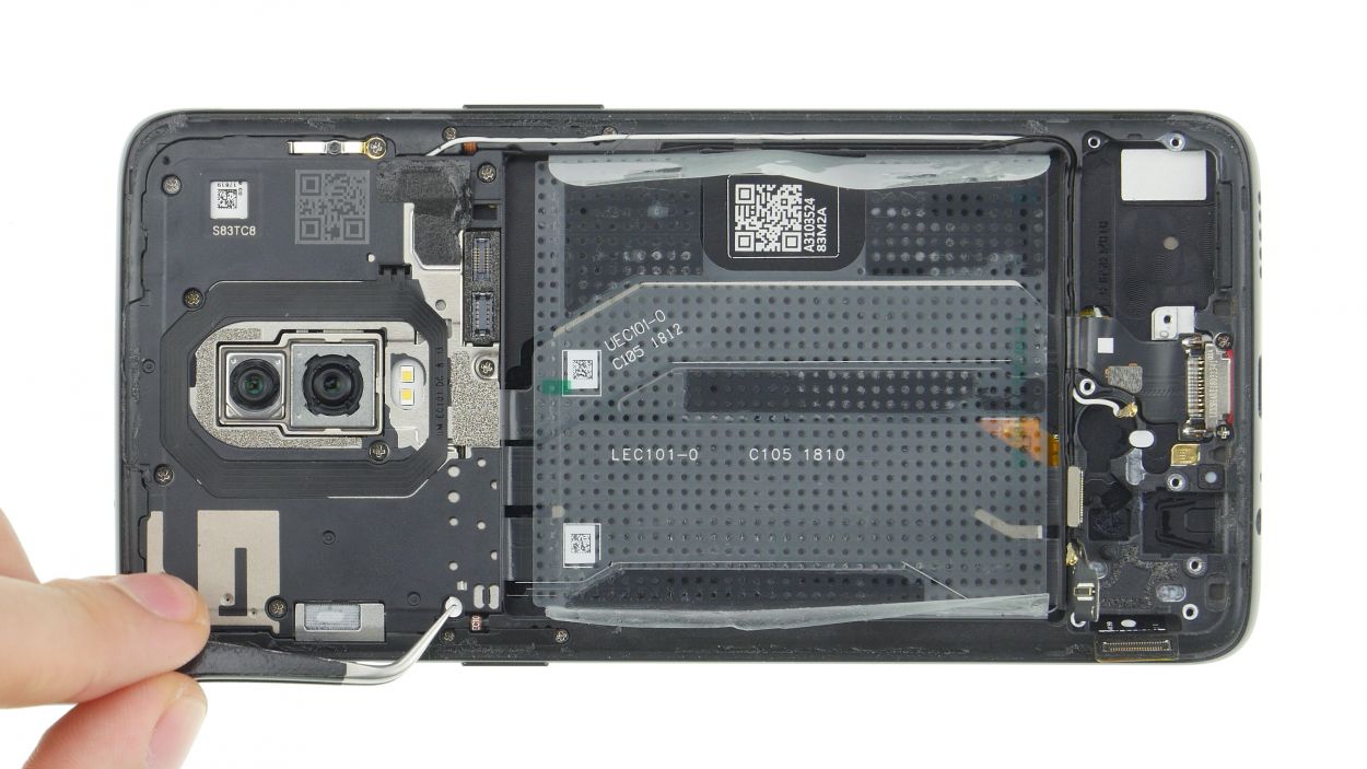
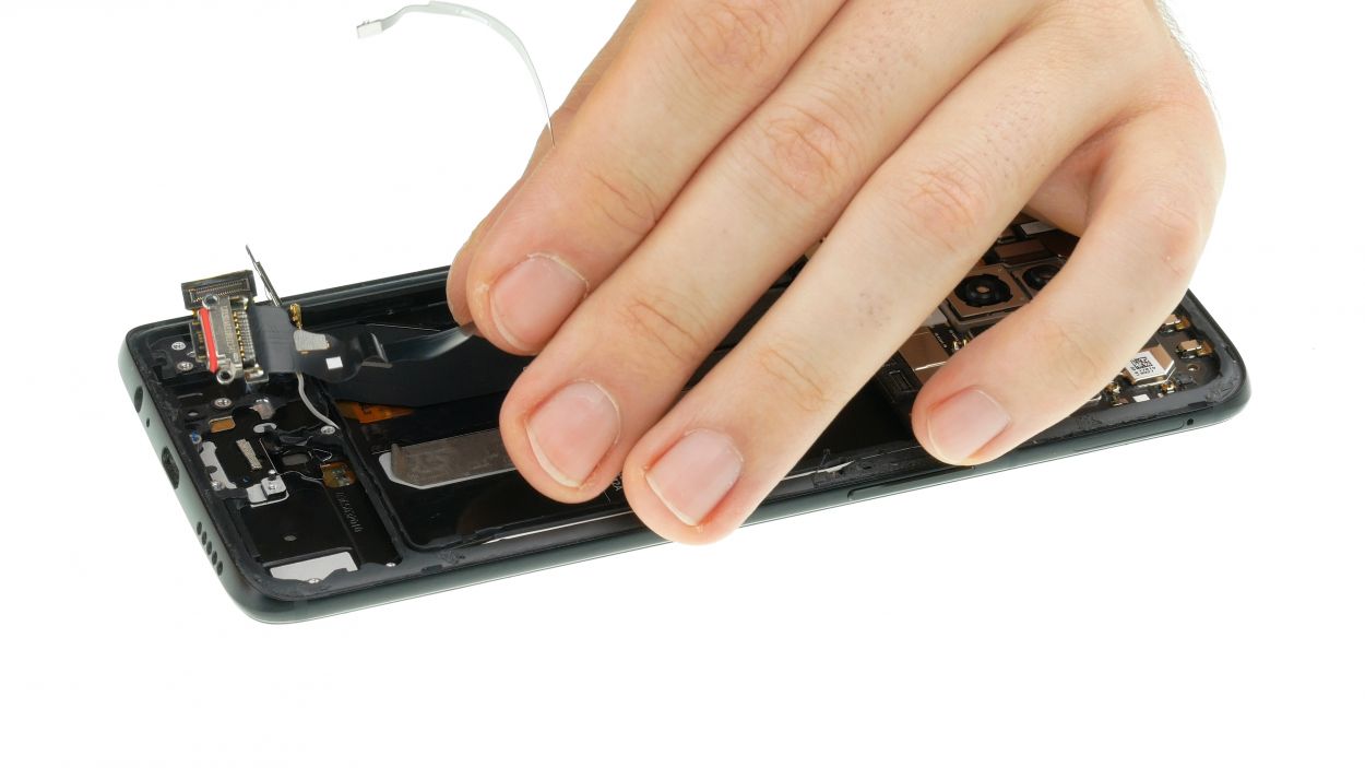
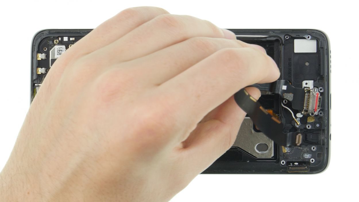
If the cable is stuck on there like it’s having a party, just bring in some hot air to help it chill out and loosen that adhesive!
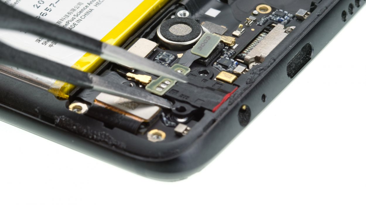
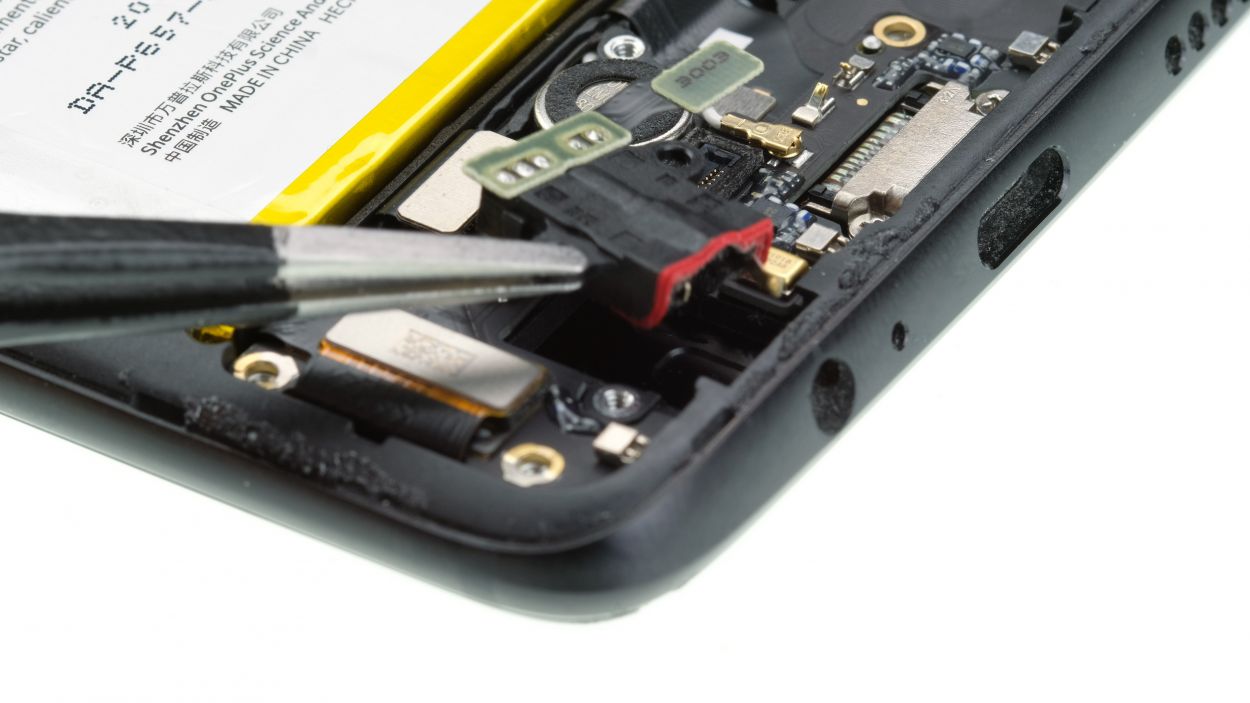
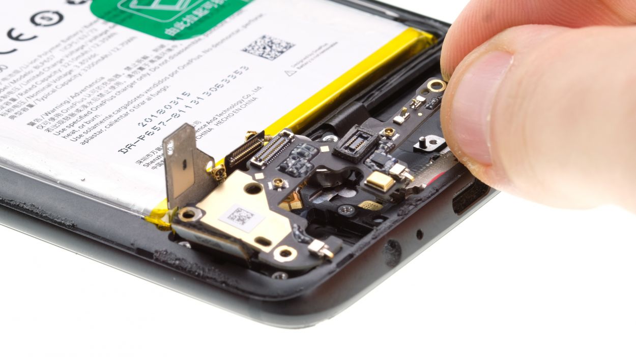
– Disconnect the marked connector of the USB flexible cable with the Pry Tool.
– Remove the marked screws from the USB connector.
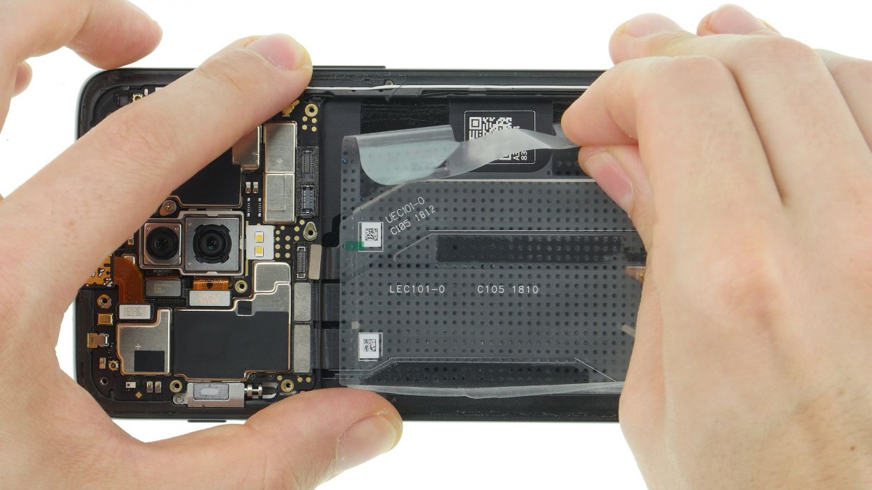
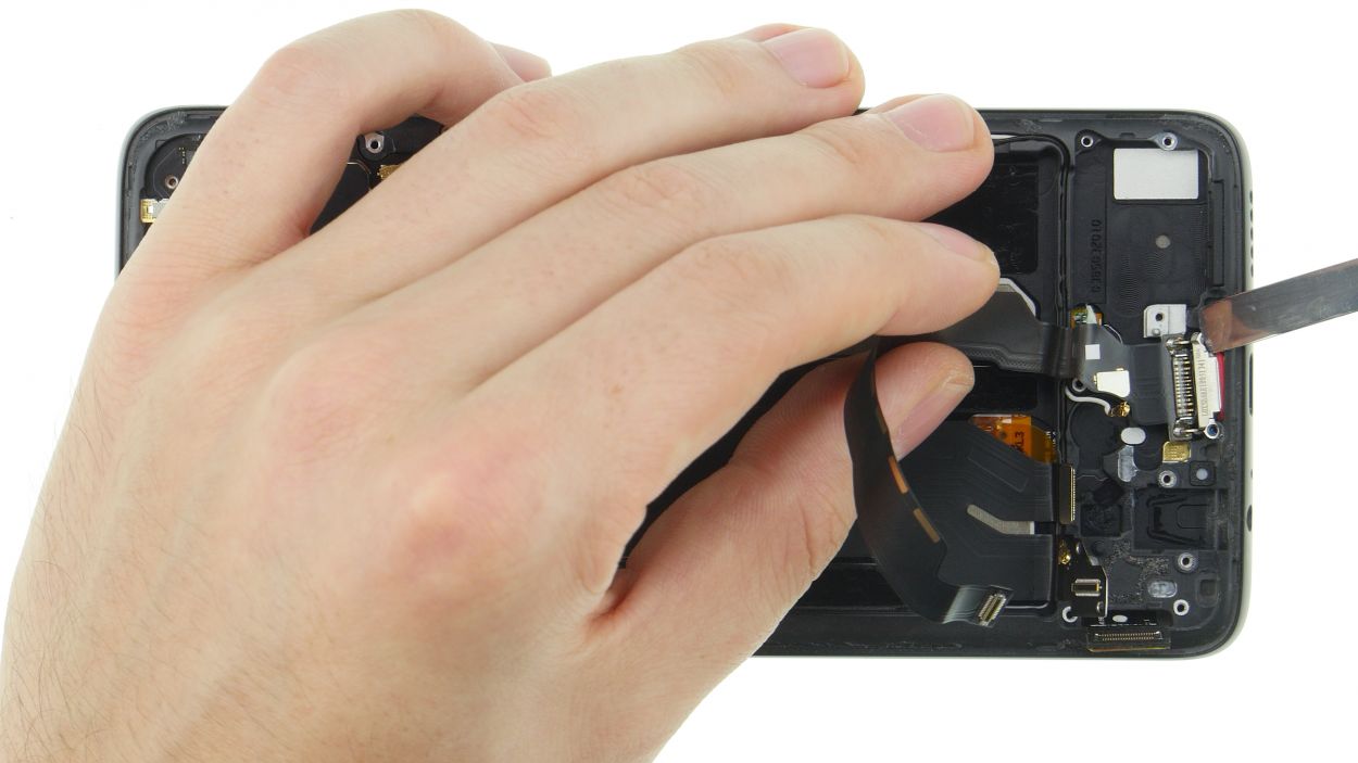
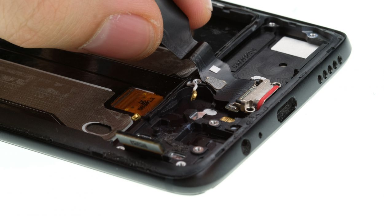
– Remove the adhesive foil that is attached over the flex cables.
– Remove the rubber strip that attaches the flex cables to the edge.
– Now you can carefully loosen the flex cable by pulling it out of the case one by one.
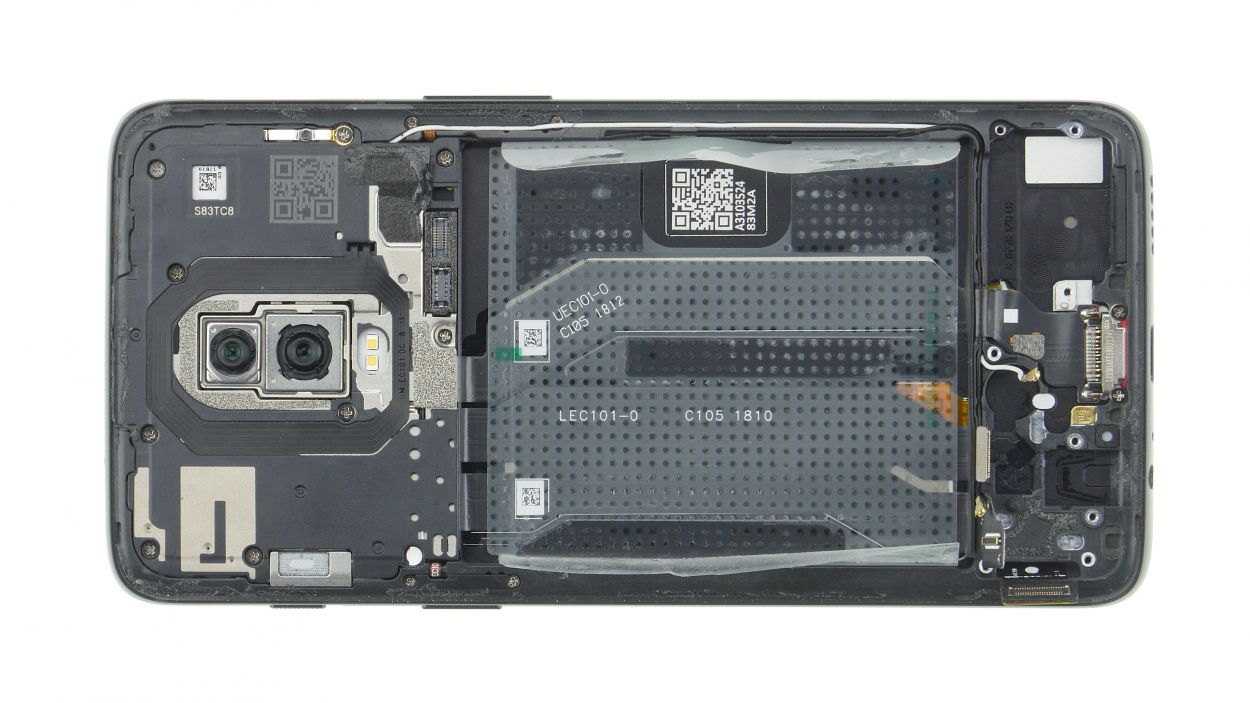
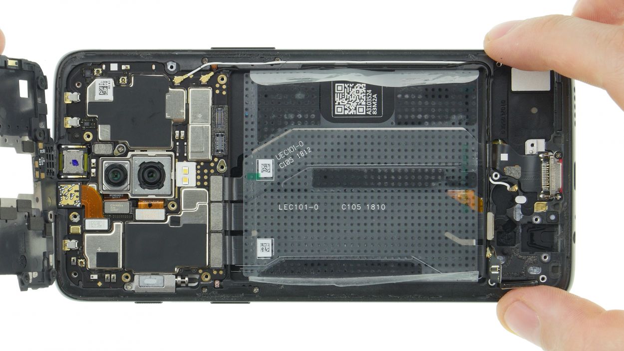
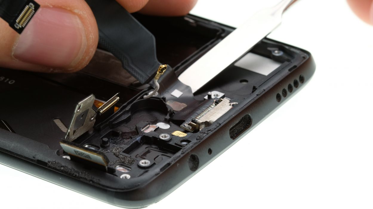
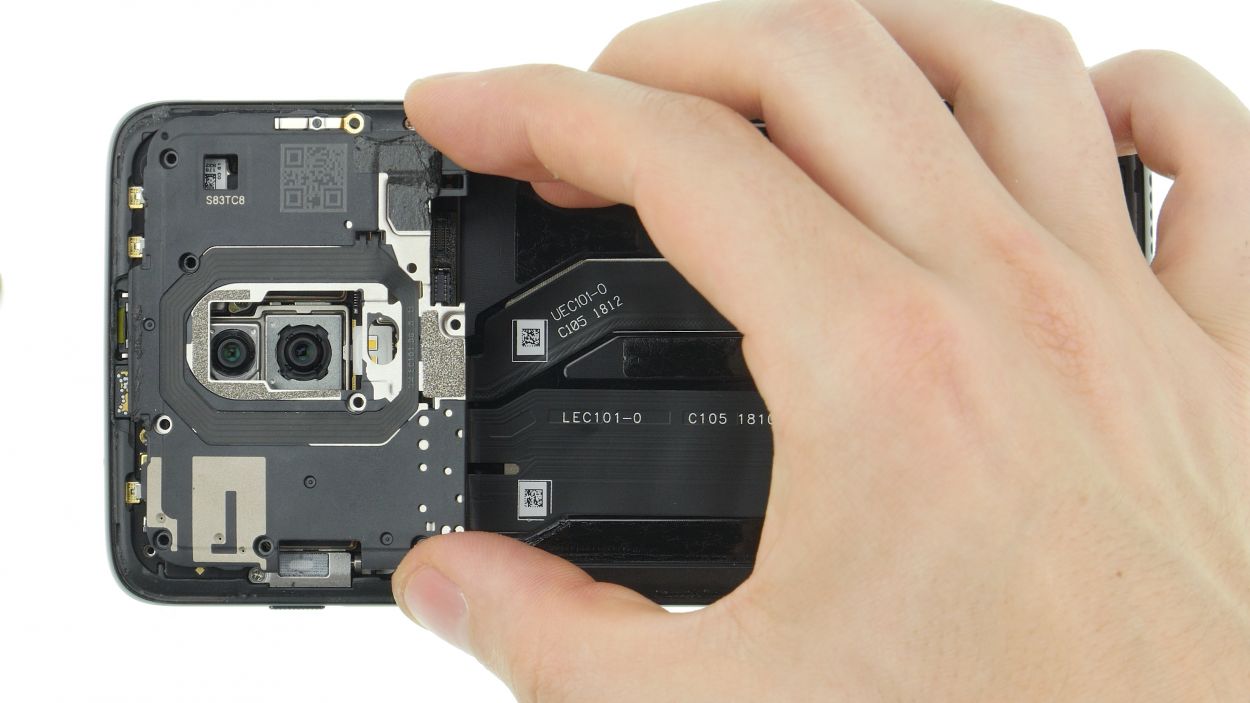
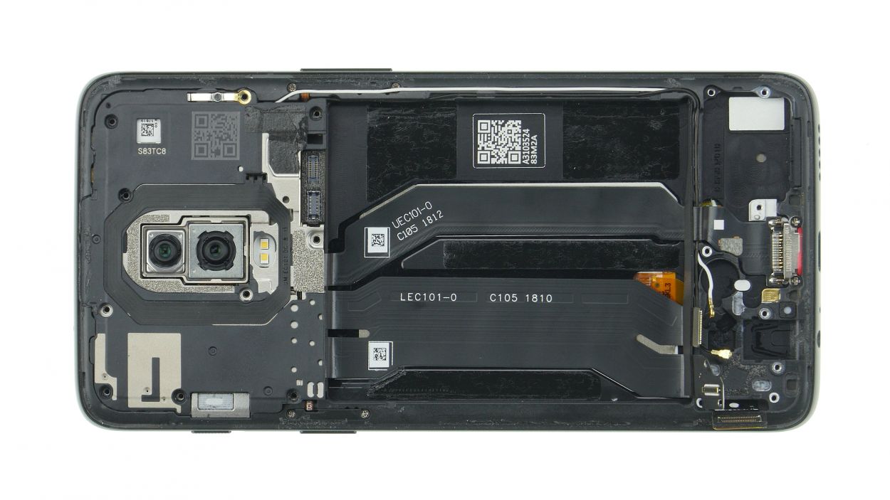
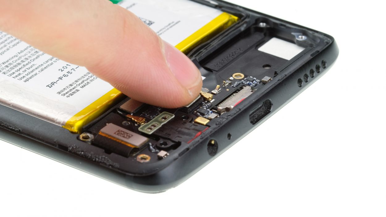
Step 11
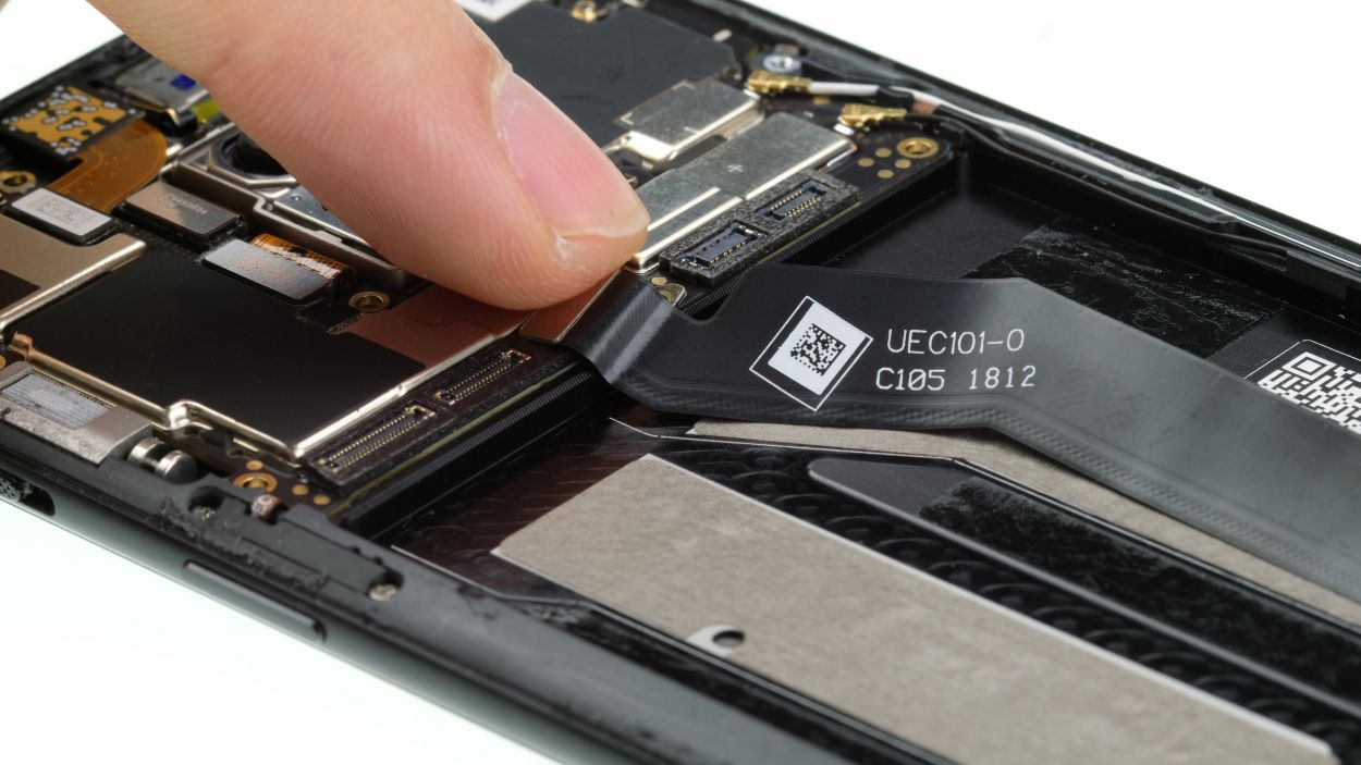
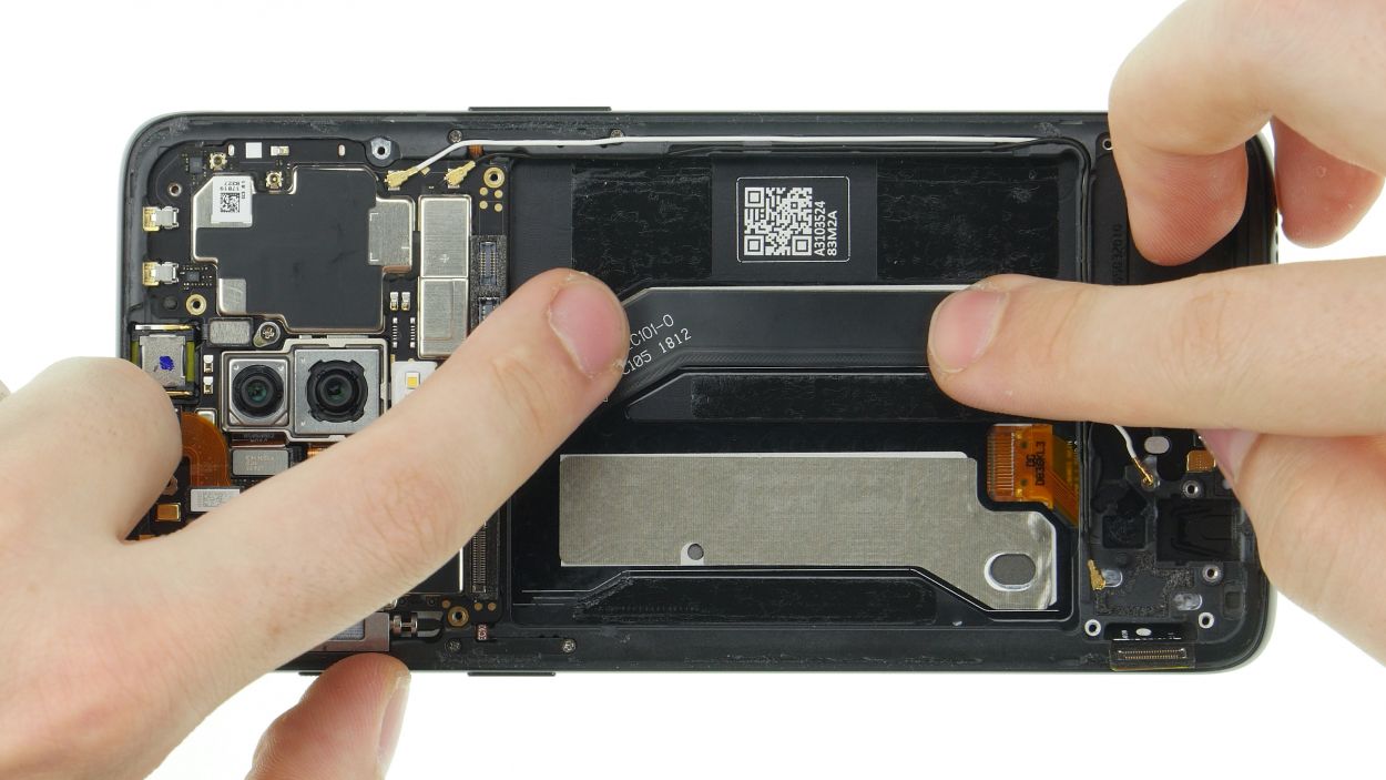
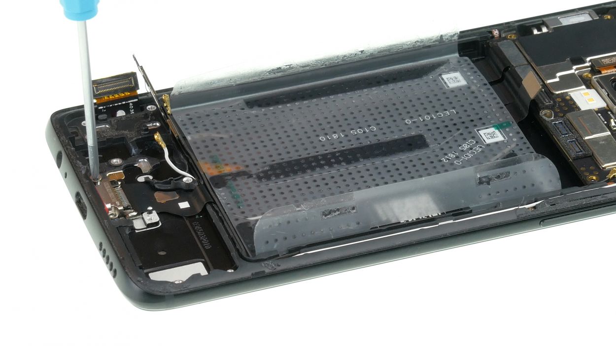
2 × 2,4 mm Phillips
USB-Flex Connector
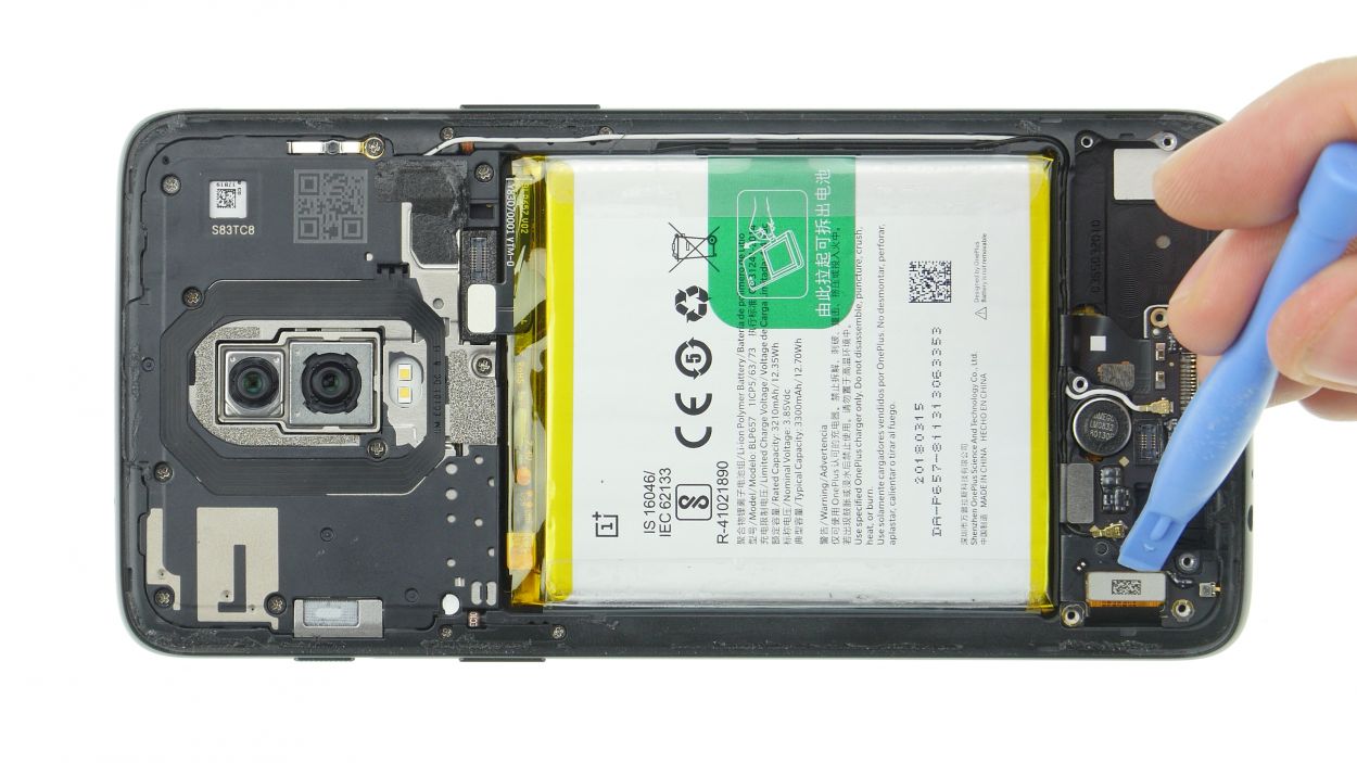
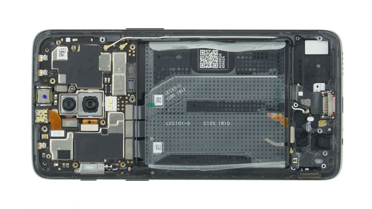
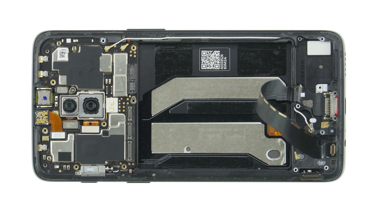
In the images, you’ll notice that the display flex cable is absent, but no worries! You don’t need to take it out to swap in the new USB flexible cable. Just keep calm and carry on with the repair! If you need help, you can always schedule a repair.
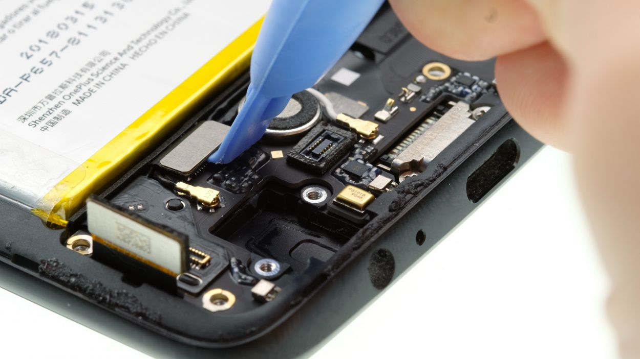
– Slide that USB port right into the cozy little opening at the bottom of the frame. Give it a gentle press to make sure it snuggles in just right.
– Grab your trusty Phillips screwdriver and secure the socket with those screws. Nice and tight!
– Next up, connect the connector to the mainboard. It’s like a handshake between friends!
– Press the cable down firmly, but be gentle—no need to crinkle or bend it. Treat it like the delicate gem it is!
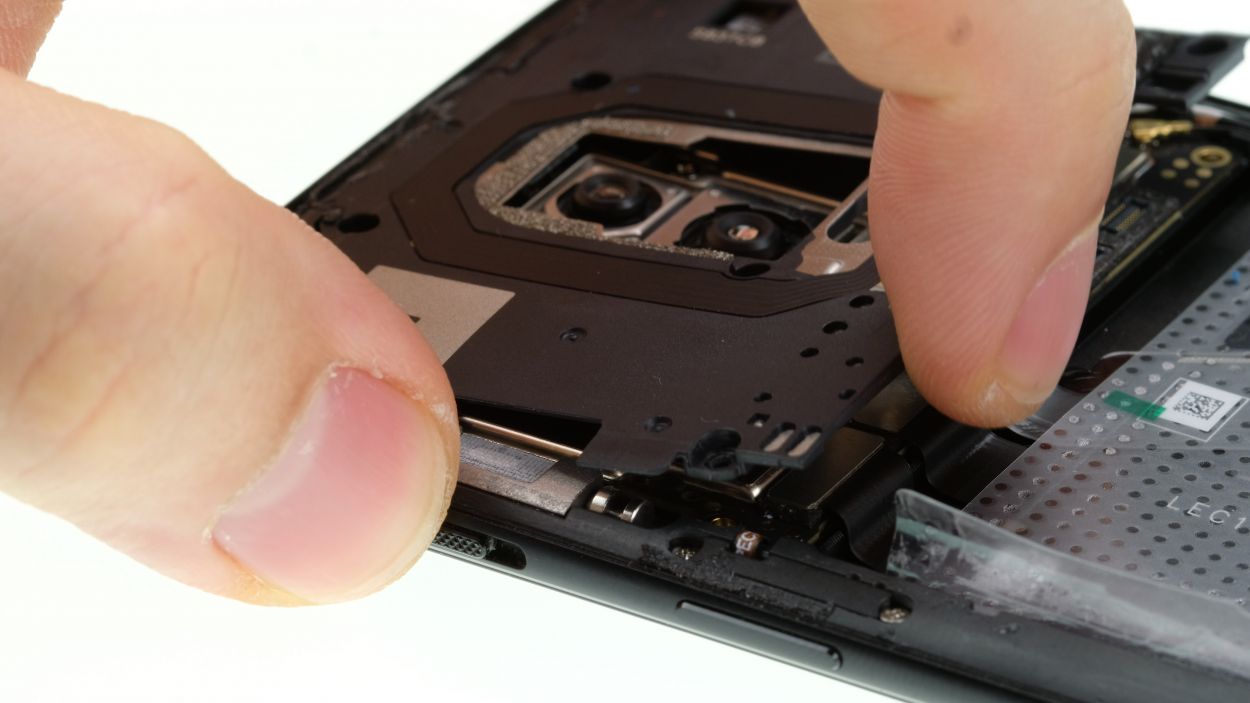
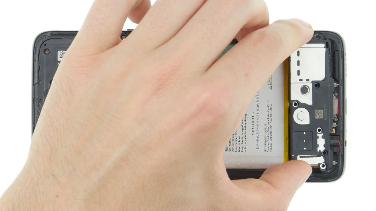
Step 12
10 × 3,0 mm Phillips
Ensure that the edges fit snugly into the frame and don’t stick out too far. You’ve got this!
– Put the cover on top and press it down.
Step 13
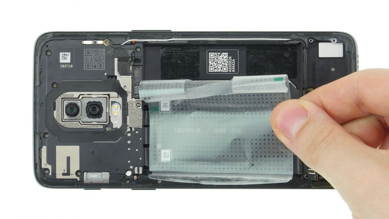
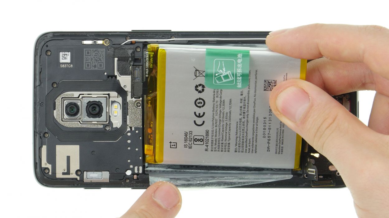
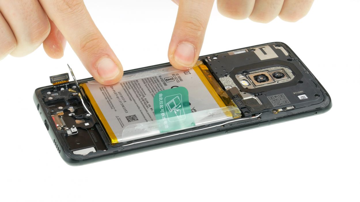
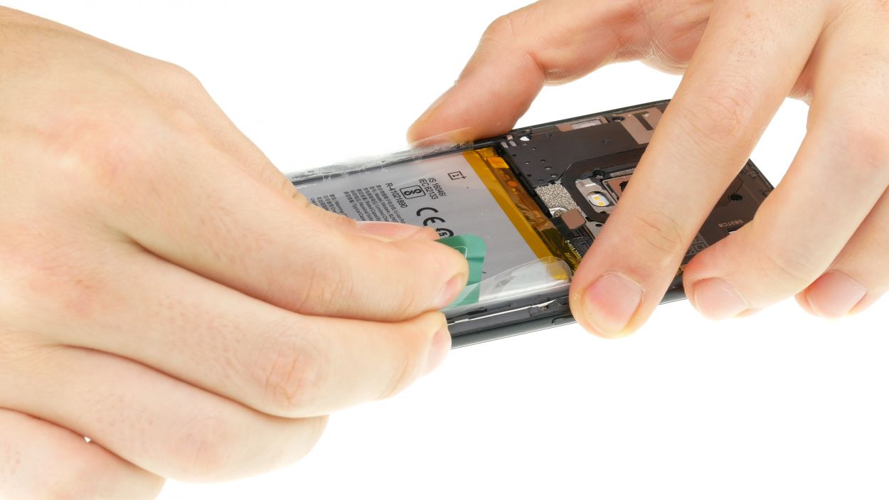
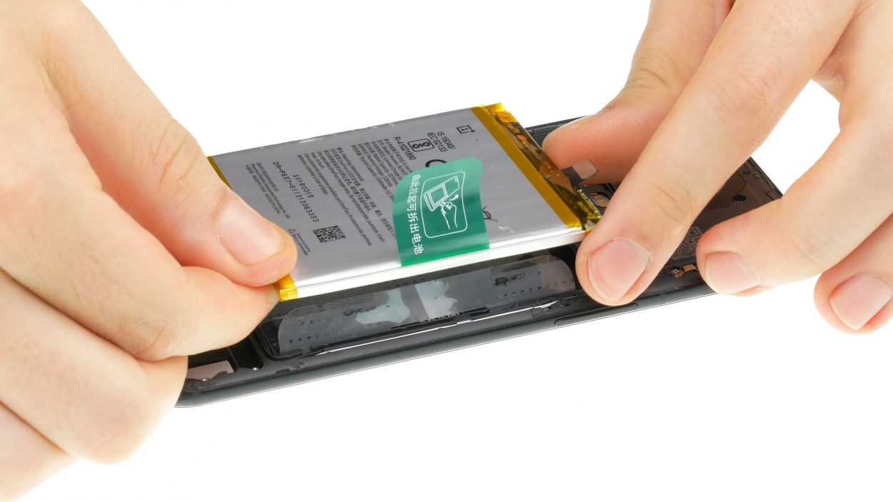
– Step 1: Reattach that slick new sticker! Place the transparent foil back in before inserting the battery. Trust us, you’ll thank us later…less hassle, more happiness.
– Step 2: Slap that battery in its spot! Make sure it’s got some breathing room around it, no squishing or crushing, just comfy and cozy.
– Step 3: Let’s get connected! Double-check that the battery contact is right on top of its socket – it’s like finding the perfect Bluetooth match.
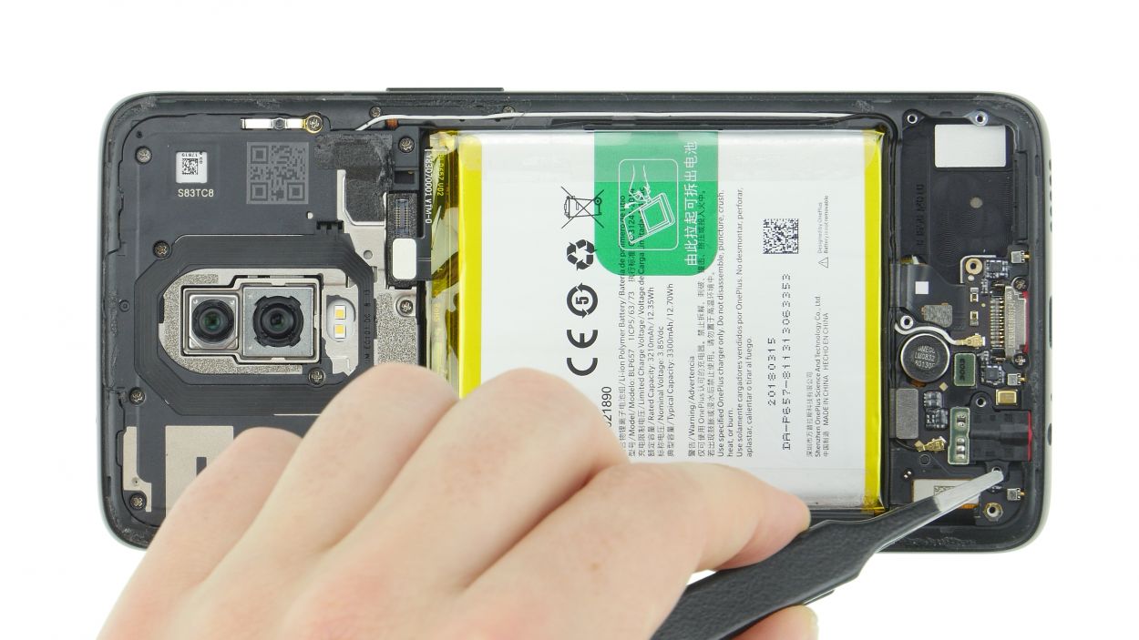
Step 14
Make sure the antenna cables are properly routed.
– Go ahead and place the lower board back in its happy little spot. Make sure it’s snug and comfy everywhere. Keep an eye on those tiny openings – they’re right above the device’s adorable noses!
– Next up, pop the display cable plug onto the board. The round opening is there to help you line it up perfectly!
– Great job! Now, connect the display connector to the mainboard. It’s a match made in tech heaven!
– Almost there! If you need help, you can always schedule a repair. For now, use your trusty tweezers to connect the antenna connectors. Line up the plugs above their sockets and give ’em a friendly press with a spudger.
Step 15

– Get ready to put on a show; it’s time to insert the headphone jack like a pro! Make sure that lovely golden pin goes right through that opening. We’re talking ‘straight through’ precision here.
– Now give that jack a good squeeze and pop the connector into place. You got this!
Step 16

8 × 3,0 mm Phillips
– Attach the speaker to the lower edge and press it firmly until it is in place.
– Screw the speaker in with the Phillips screws.
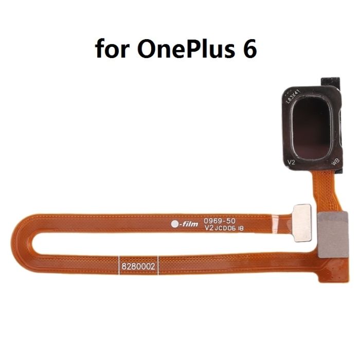
Step 18
Fingerprint Connector
– Grab that back cover and set it right next to your device, ready for action!
– Carefully lay the fingerprint sensor cable over its mainboard buddy and give it a nice connection.
– Now, pop on the cover with the red rubber piece and seal the deal with the black glue.
Step 19

– First things first, fire up your device and give that screen a quick check!
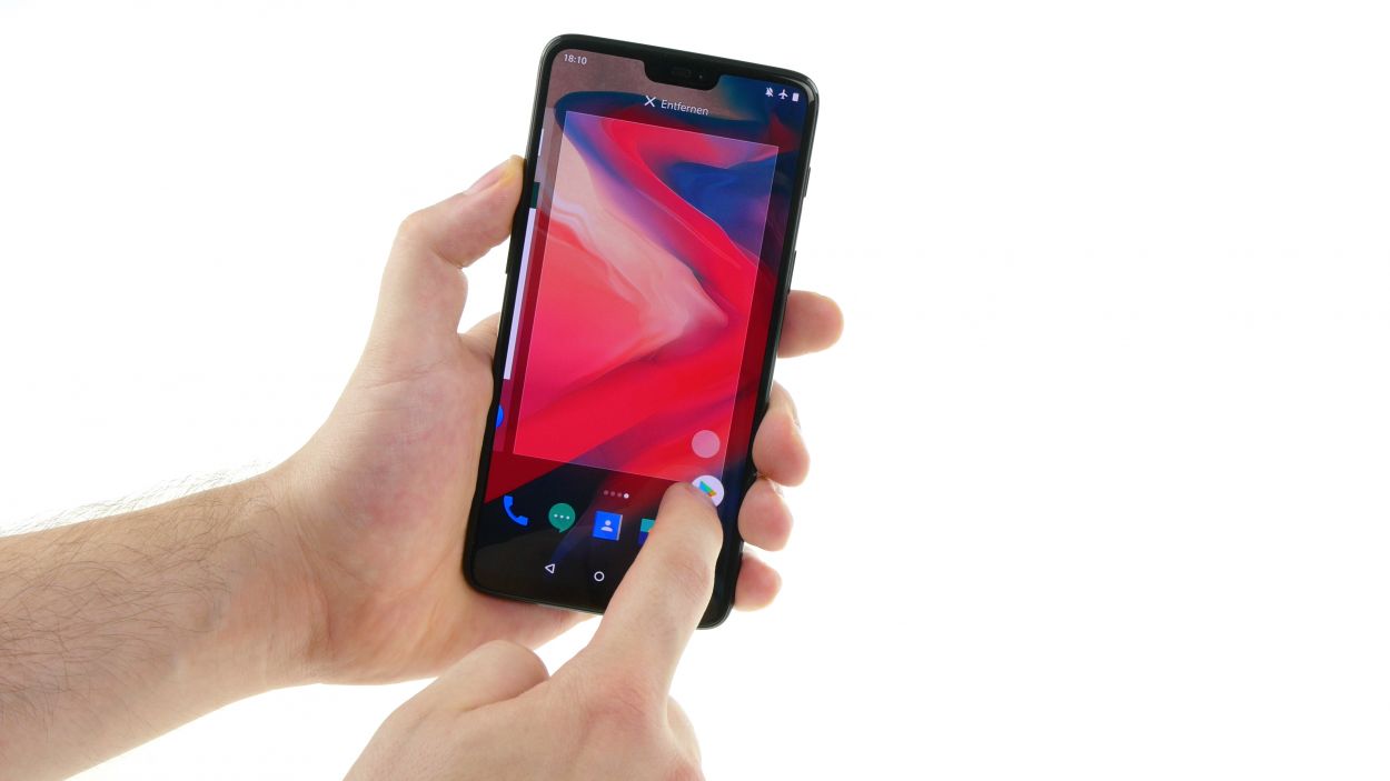
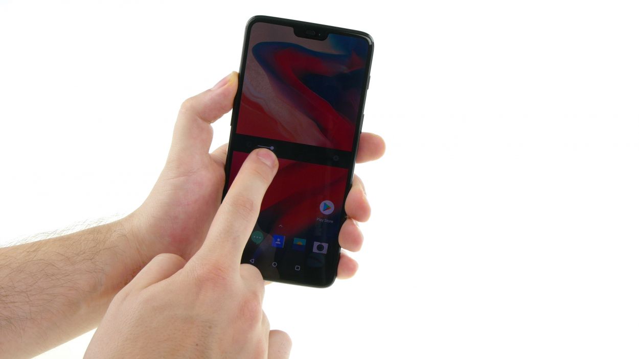
– Slide an app along the edge and zigzag it across the display—let’s see if the touchscreen is feeling responsive everywhere!
– Give the brightness a whirl, testing both the lowest and highest settings.
– Don’t forget to put the front and rear cameras, along with the flash, to the test!
– Make a call and see how the microphone and earcup are holding up.
– And for the grand finale, mute the phone and see if that vibration motor is still buzzing with life!
Step 20

Clamp the device between a few books for example and give the glue an hour to set.
– Heat the device again to soften the glue of the back cover.
– Press the back cover firmly onto the frame of the device.