DIY Guide to Removing the Logic Board of Fairphone 1
Duration: 30 min.
Steps: 16 Steps
In this guide, we’ll walk you through the process of removing your Fairphone’s PCB all by yourself! If you’re keen on giving your logic board a little TLC, you’ll want to follow these steps to get it out.
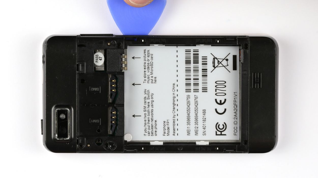
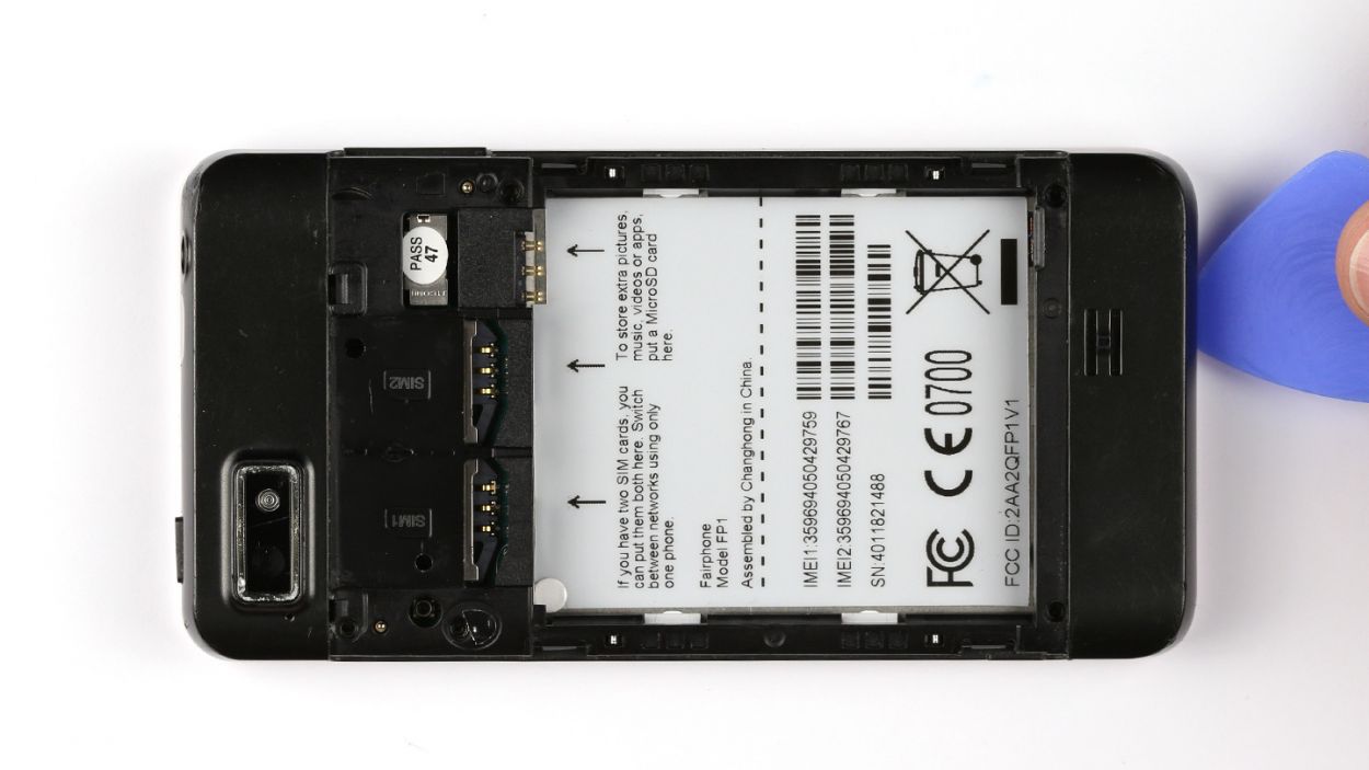
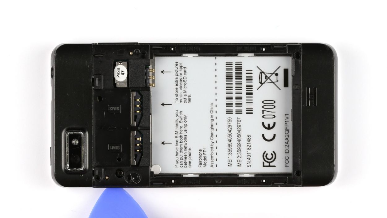
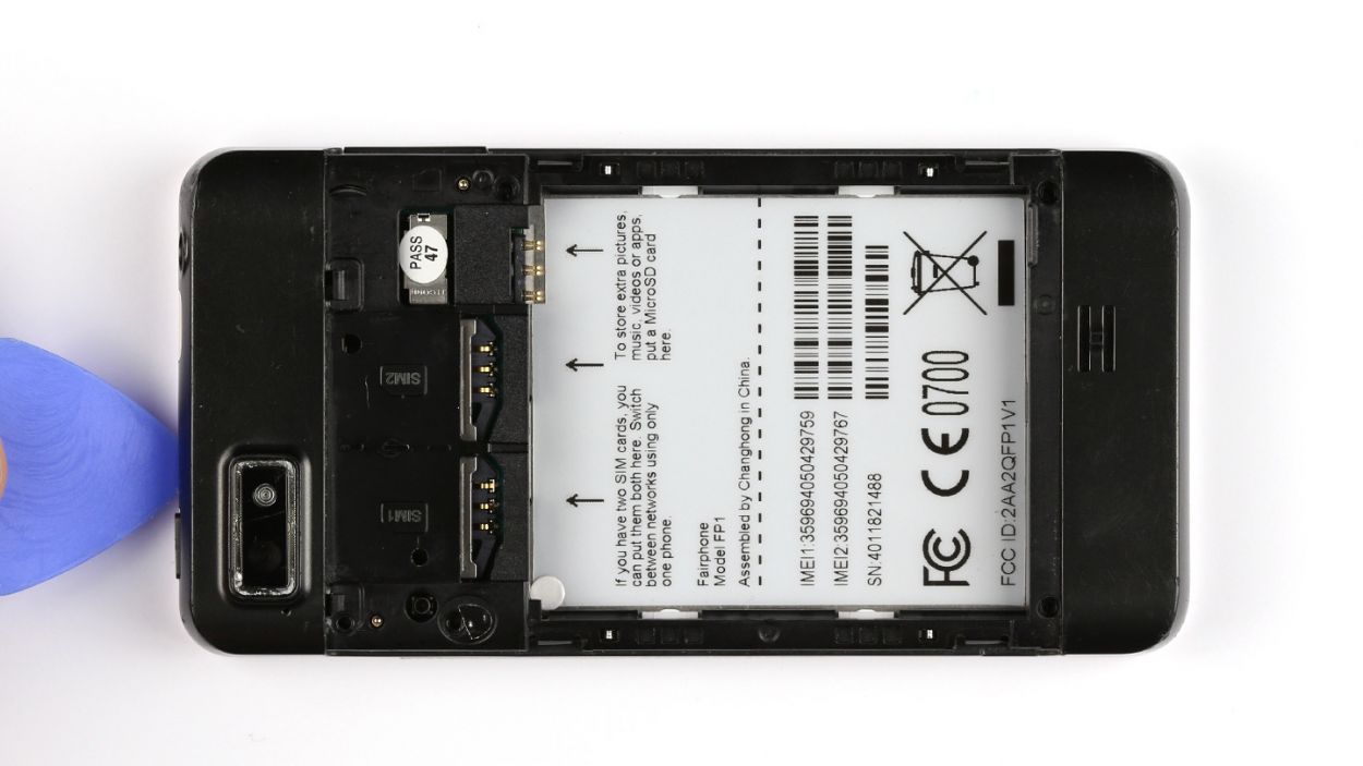
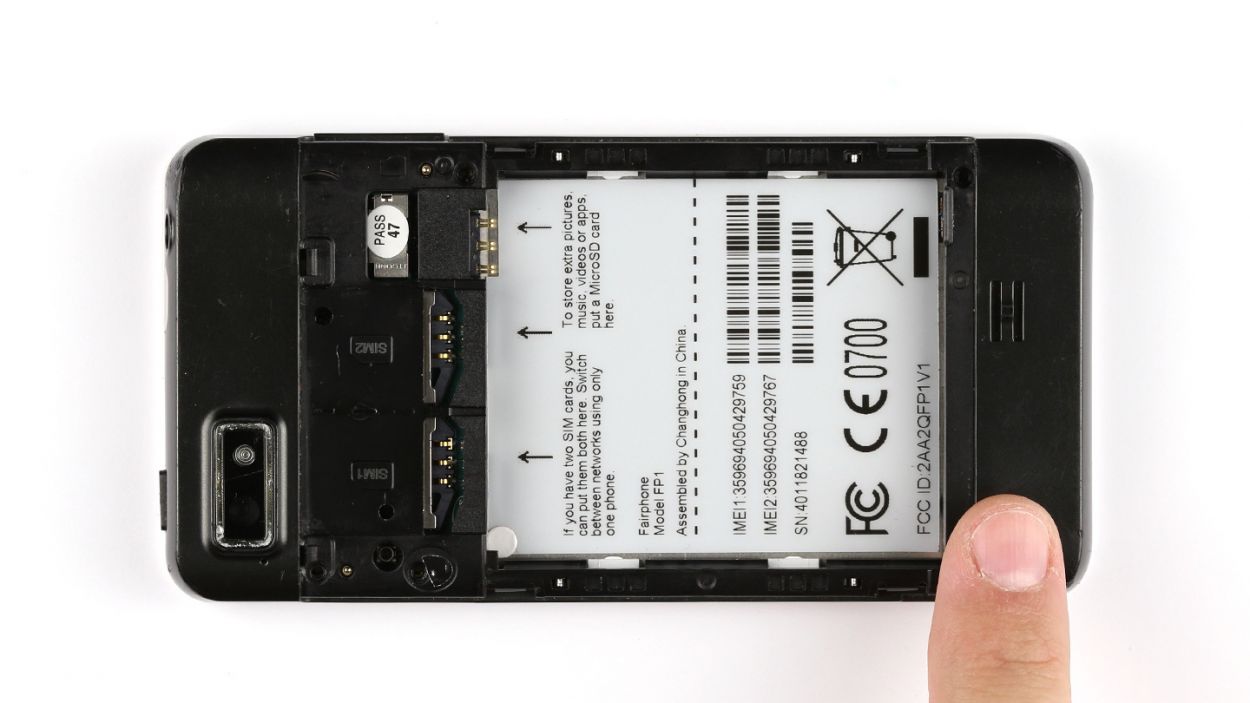
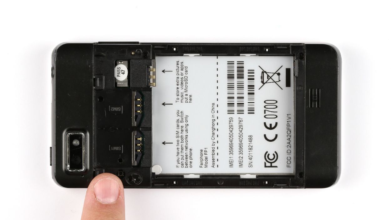
Step 1
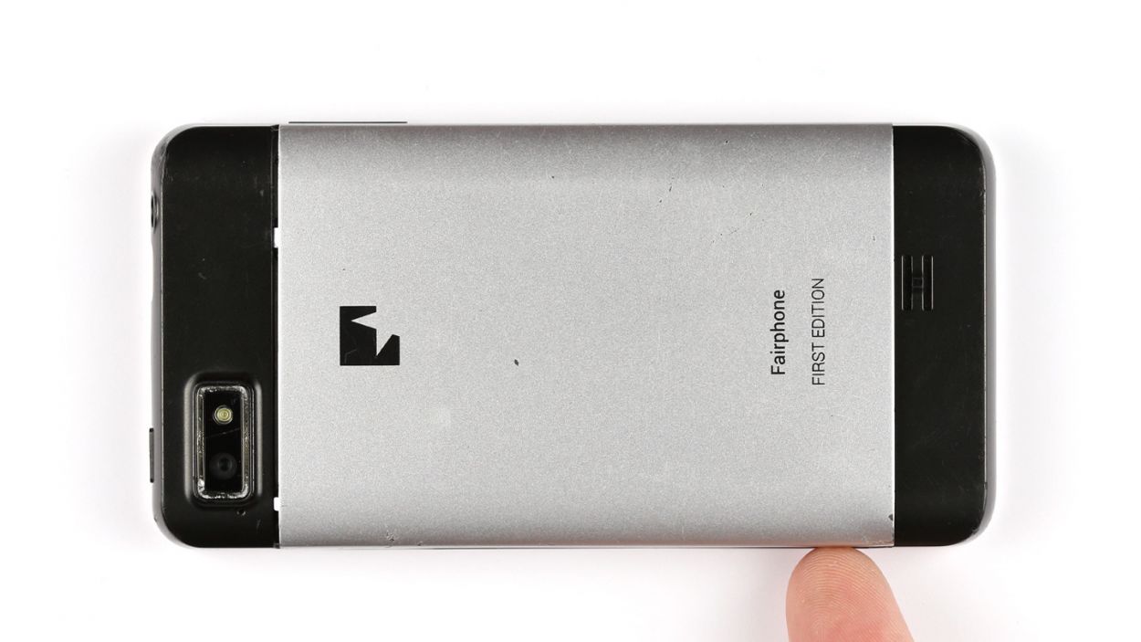

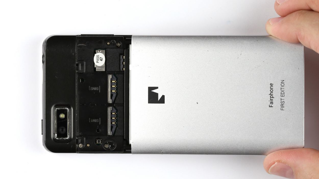
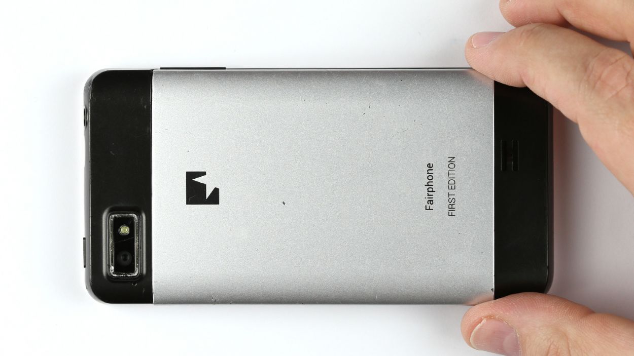
– Give that back cover a little lift with your finger to pop it off your smartphone. There’s a handy dandy indentation on the side of the Fairphone just for this!
– Gently pull the back cover away from the device.
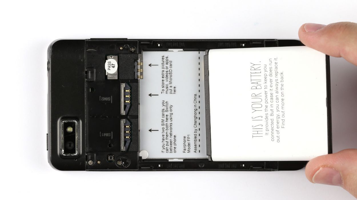
Step 2
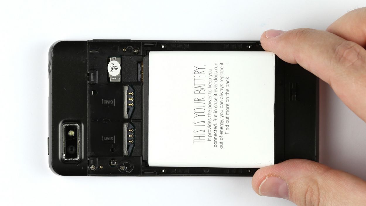

– Time to get that battery out of your Fairphone! Simply lift it up from the bottom and voilà, you’re on your way!
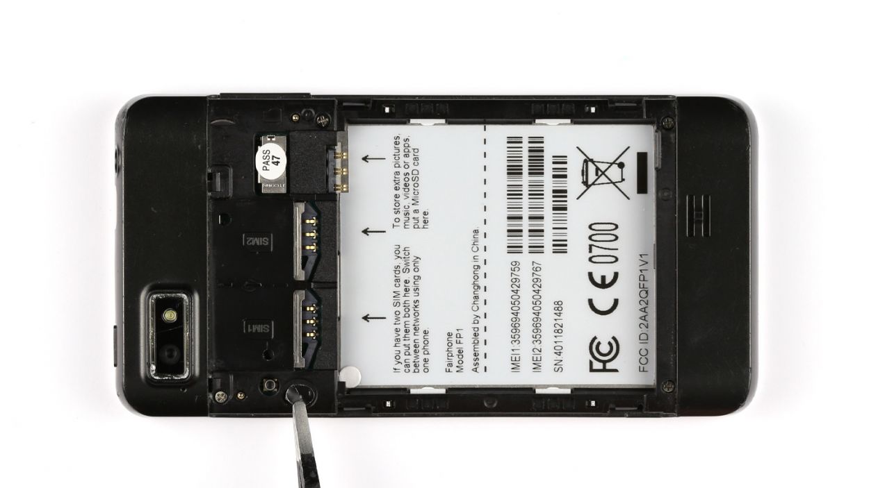
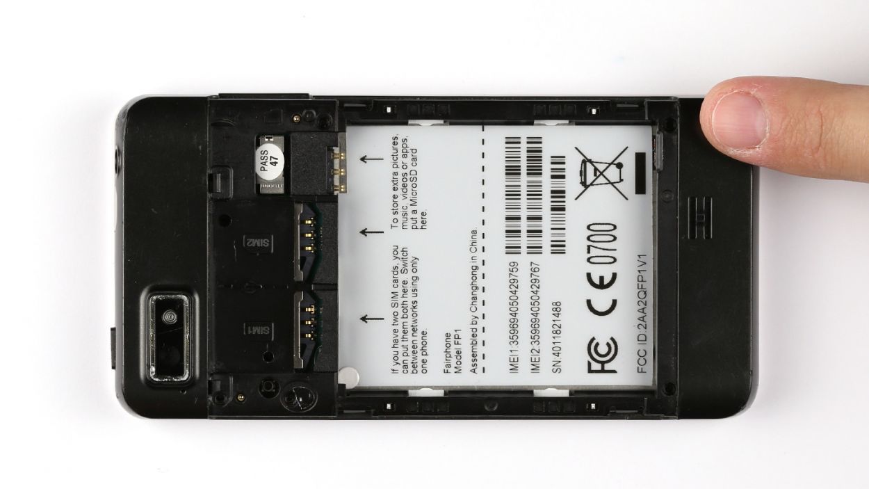
Step 3
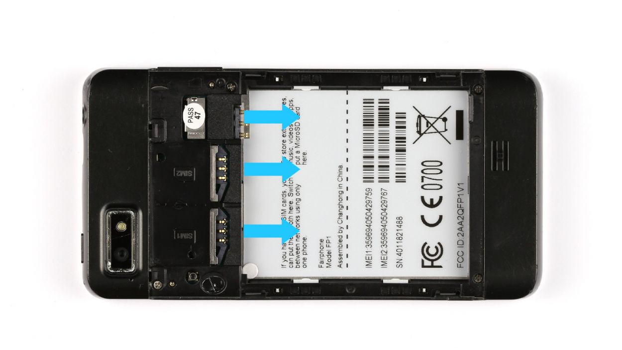
– Pop out those SIM cards and the microSD card like a pro!
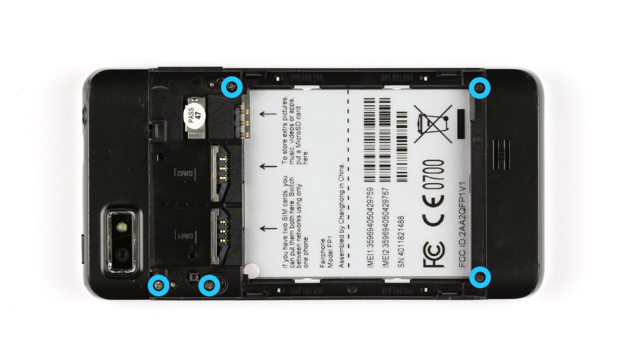
Step 4

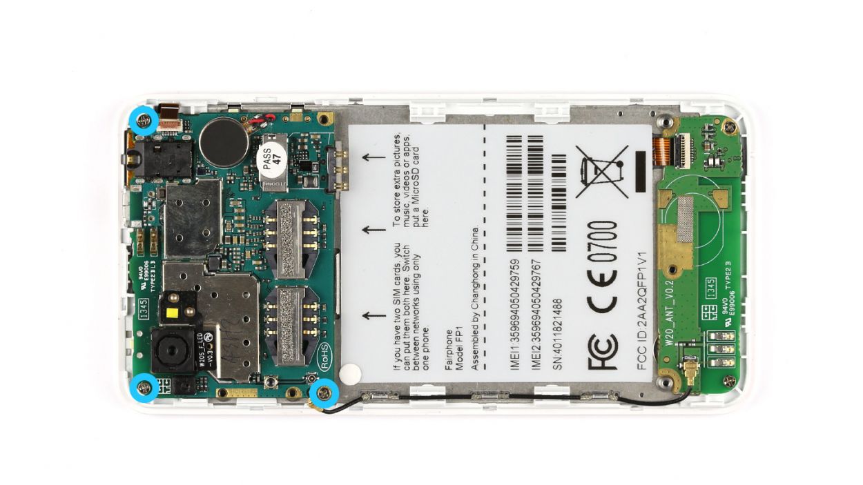
– Peel back the seal to reveal the hidden screw treasure!
– Unscrew those five Phillips screws, each measuring 5 x 3.9 mm, and let the adventure continue!


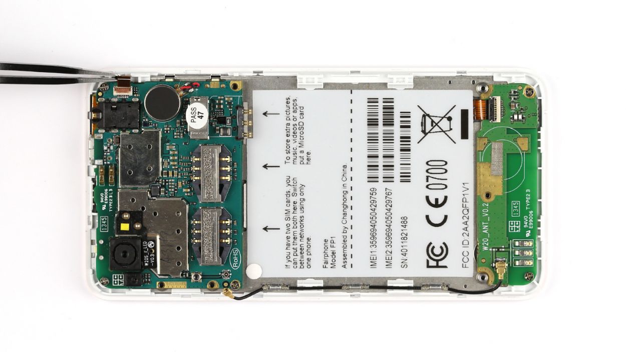
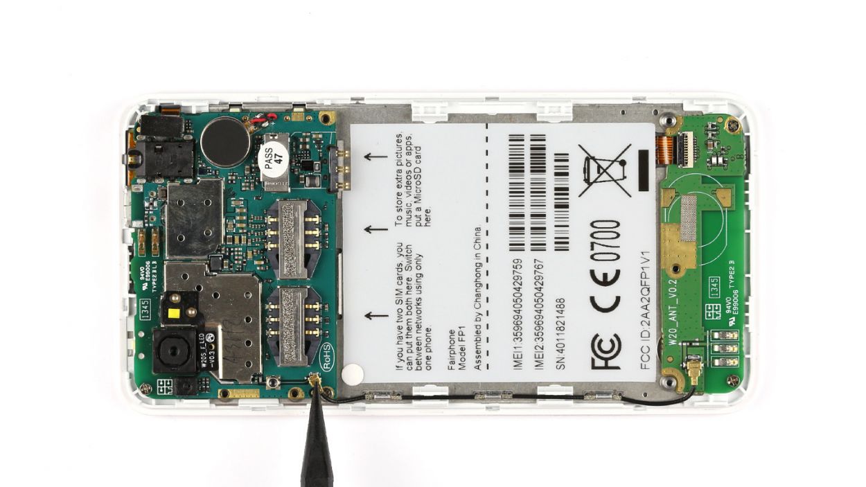
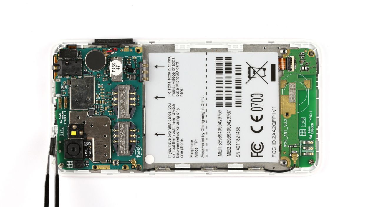
Step 7

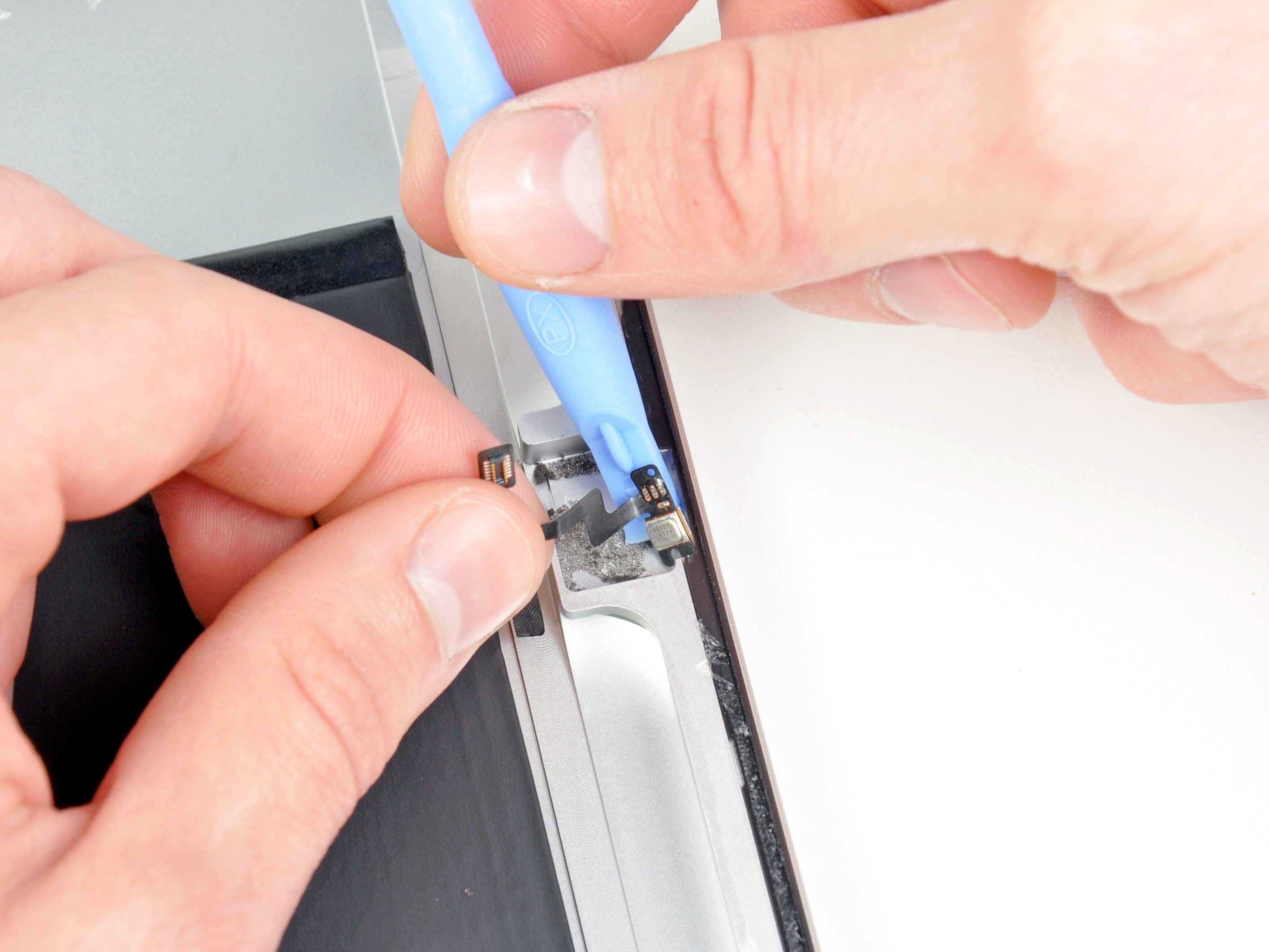
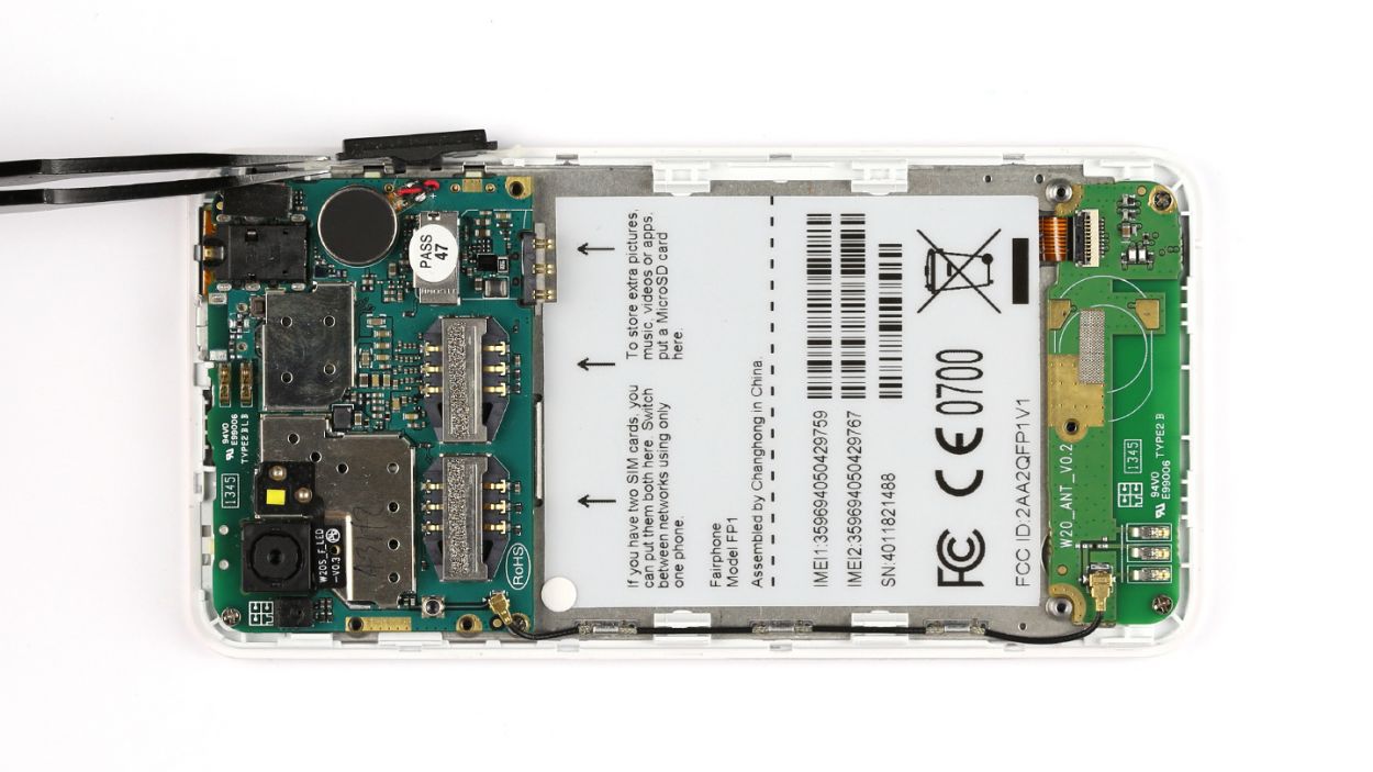
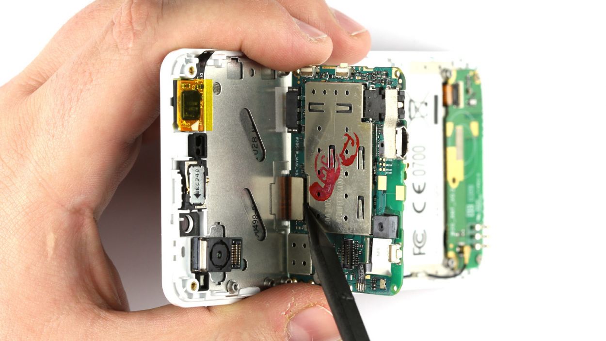
– Grab your trusty spudger and gently pry off the antenna cable from the logic board. You’ve got this!
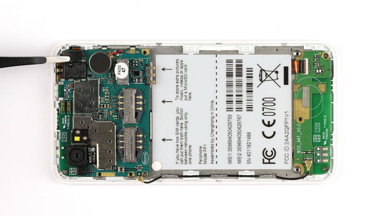
– With a steady hand, use your tweezers to delicately lift the cover off the sensor contact. Easy peasy!
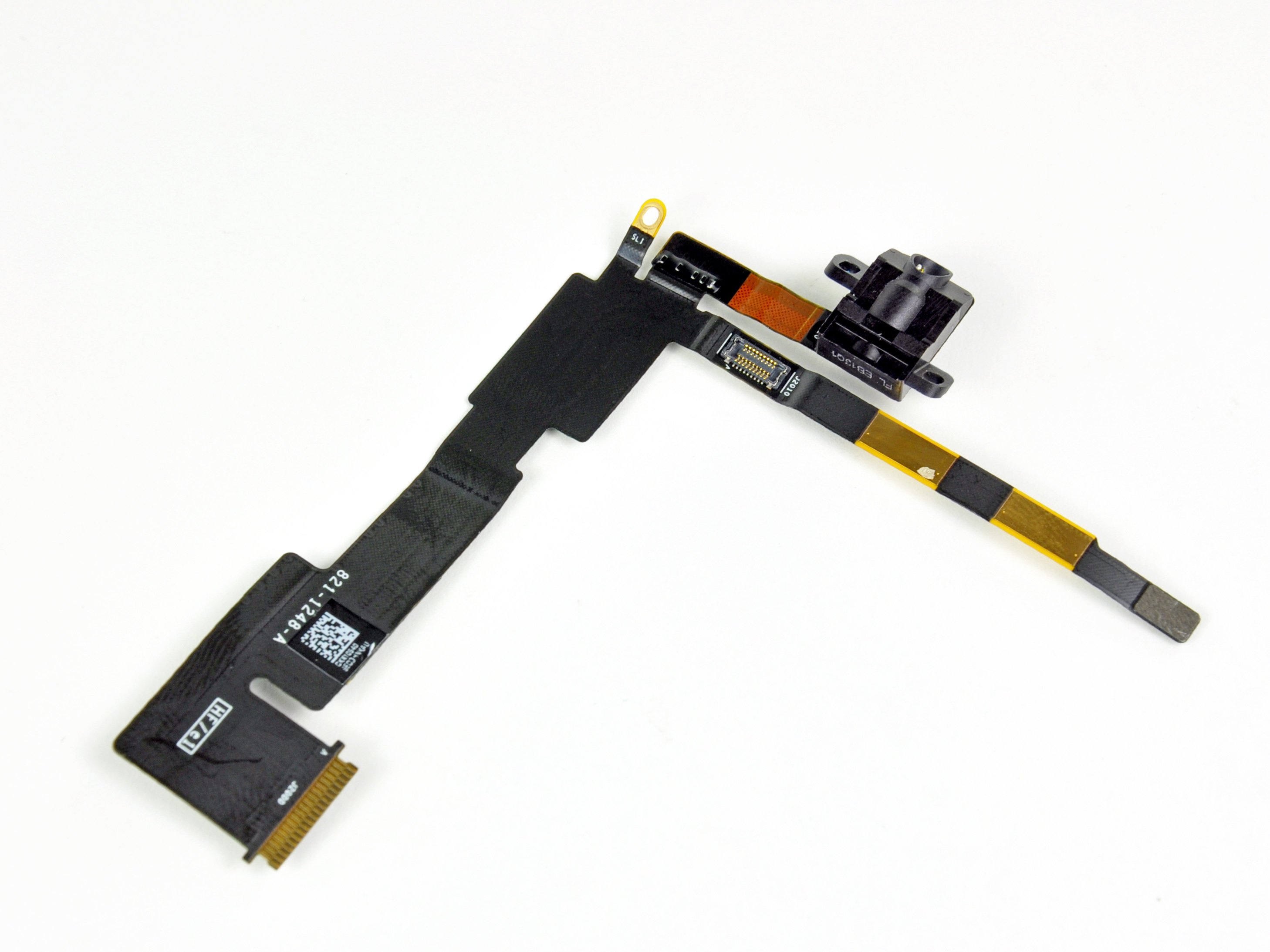
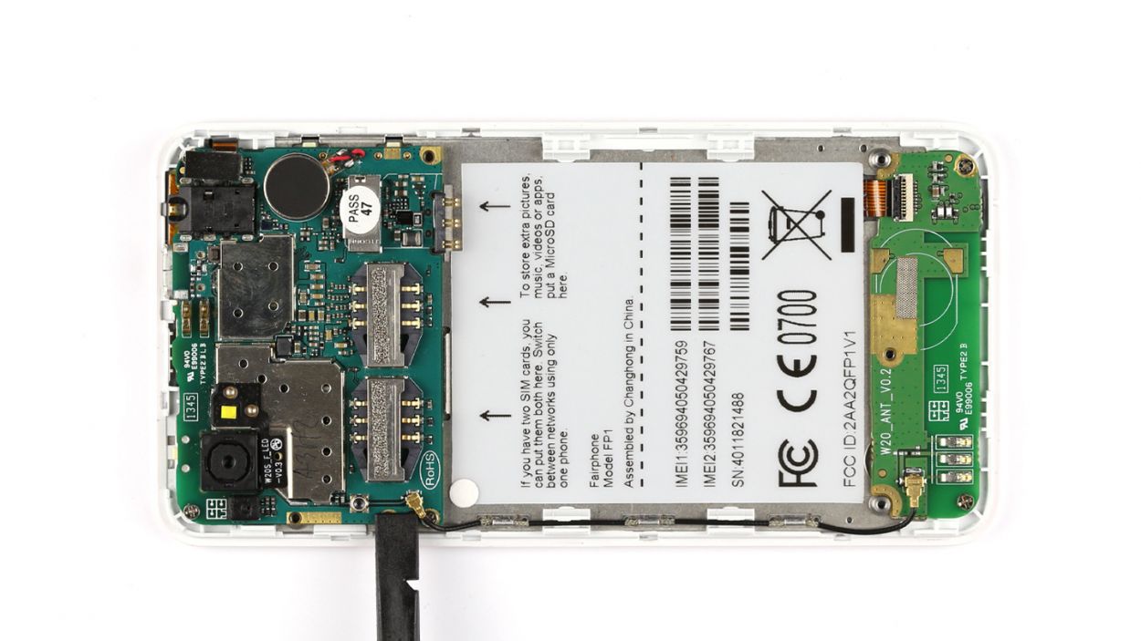
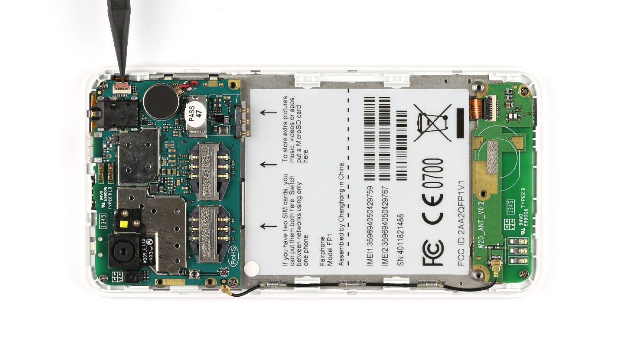
– Time to work your magic with the spudger again! Use it to free the flexible flat cable.
– Now, carefully disconnect that flexible flat cable from the logic board. You’re almost there!
Step 8


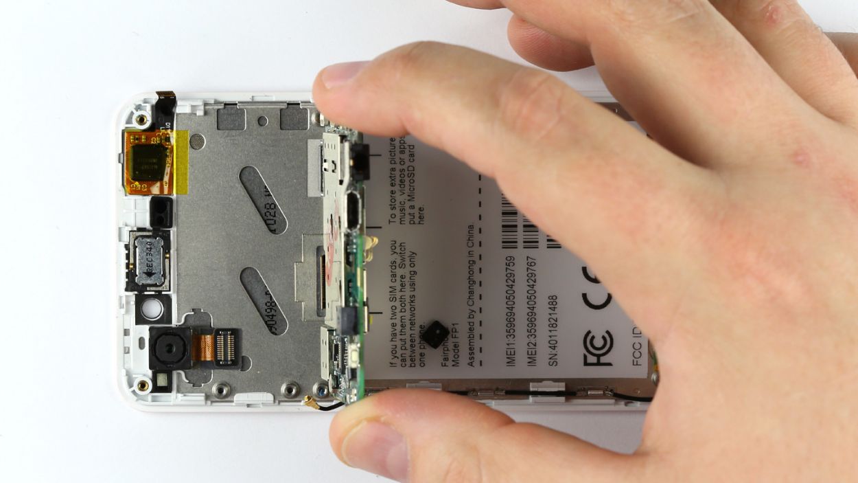
– Hey, don’t freak out! Just take a deep breath and remove those three Phillips screws (3 x 2.2 mm, don’t worry, it’s an easy peasy process!)
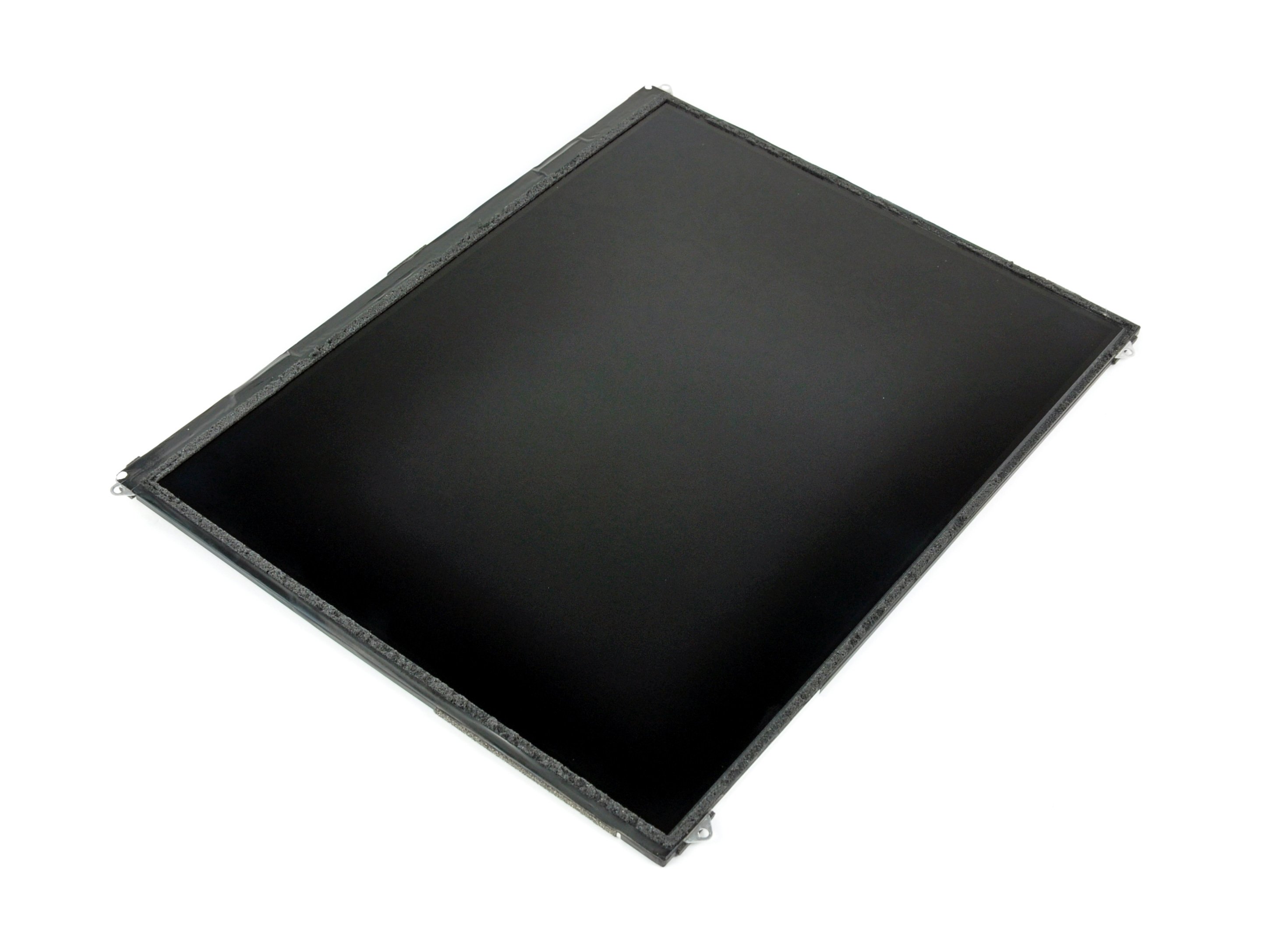
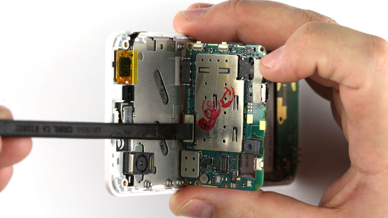
– Now, just lift that logic board, but don’t get too excited, it’s still attached to the display (think of it like a cozy little couple!).
– Time to get a little crazy! Tilt that logic board up 90° and help that display connection break free.
– Last but not least, use that spudger to disconnect the display contact. Easy peasy, lemon squeezy!
Step 9


– Gently place the logic board at a perfect 90° angle against the display.
– Next up, connect the display to the logic board like a pro.
– Carefully position the logic board back onto the display frame.
– Now, secure it in place with those three trusty Phillips screws. 3 x 2.2 mm Phillips screws, to be exact!
Step 10


– Connect the flexible flat sensor cable to the logic board.
– Lock the plug connection in place.
– Put the cover back on.
– Connect the antenna cable to the logic board.


Step 13

– Grab those five trusty Phillips screws and fasten the chassis like a pro! We’re talking about 5 x 3.9 mm Phillips screws here.
– Don’t forget to pop the seal back in place to keep everything nice and tidy.
Step 14

– Time to pop those SIM cards and microSD card back in their cozy little homes!

Step 16

– Time to get that back cover on! Just make sure those two little tabs on the back cover snugly hook into the chassis like they were made for each other.
– Give the back cover a gentle press until you hear that satisfying click. It’s like a high-five for your device!