DIY Guide to Replace Fairphone 1 Earpiece
Duration: 45 min.
Steps: 24 Steps
Hey there repair buddy! In this cheerful guide, we’ll walk you through swapping out your Fairphone’s funky earpiece. If you’re having trouble hearing conversations clearly or they’re as quiet as a library shh!, it’s time for this fix. Let’s get started!
Step 1
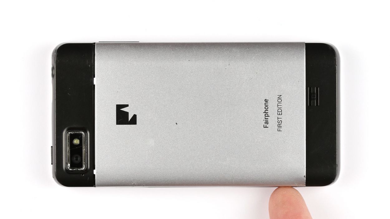

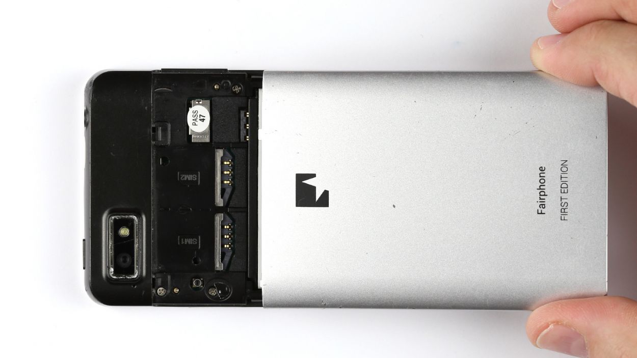
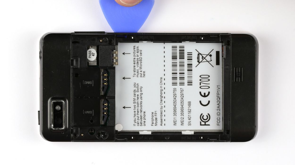
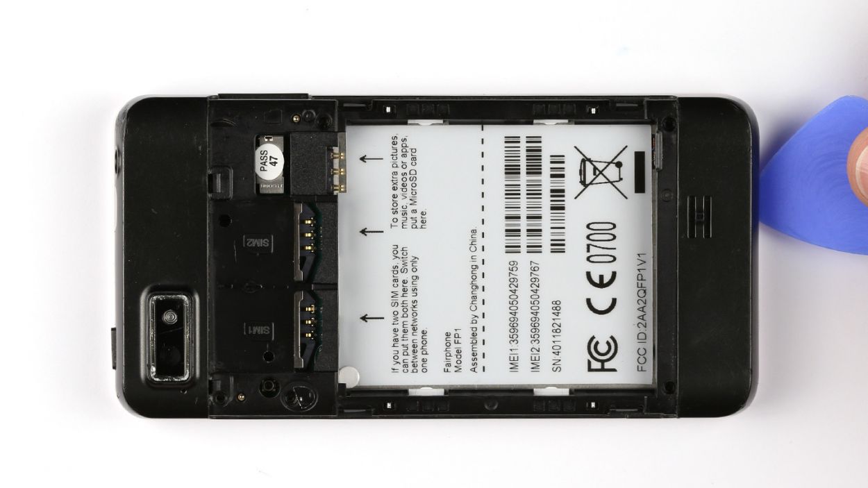
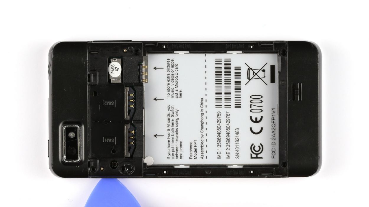
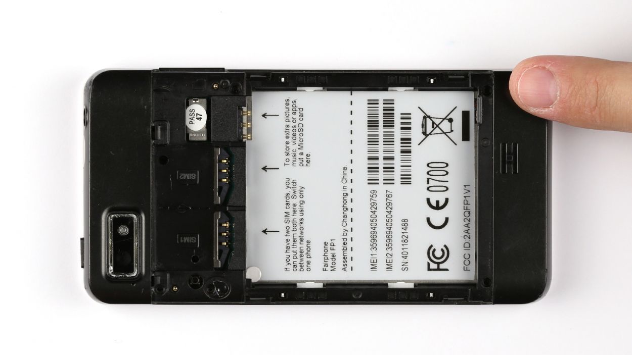
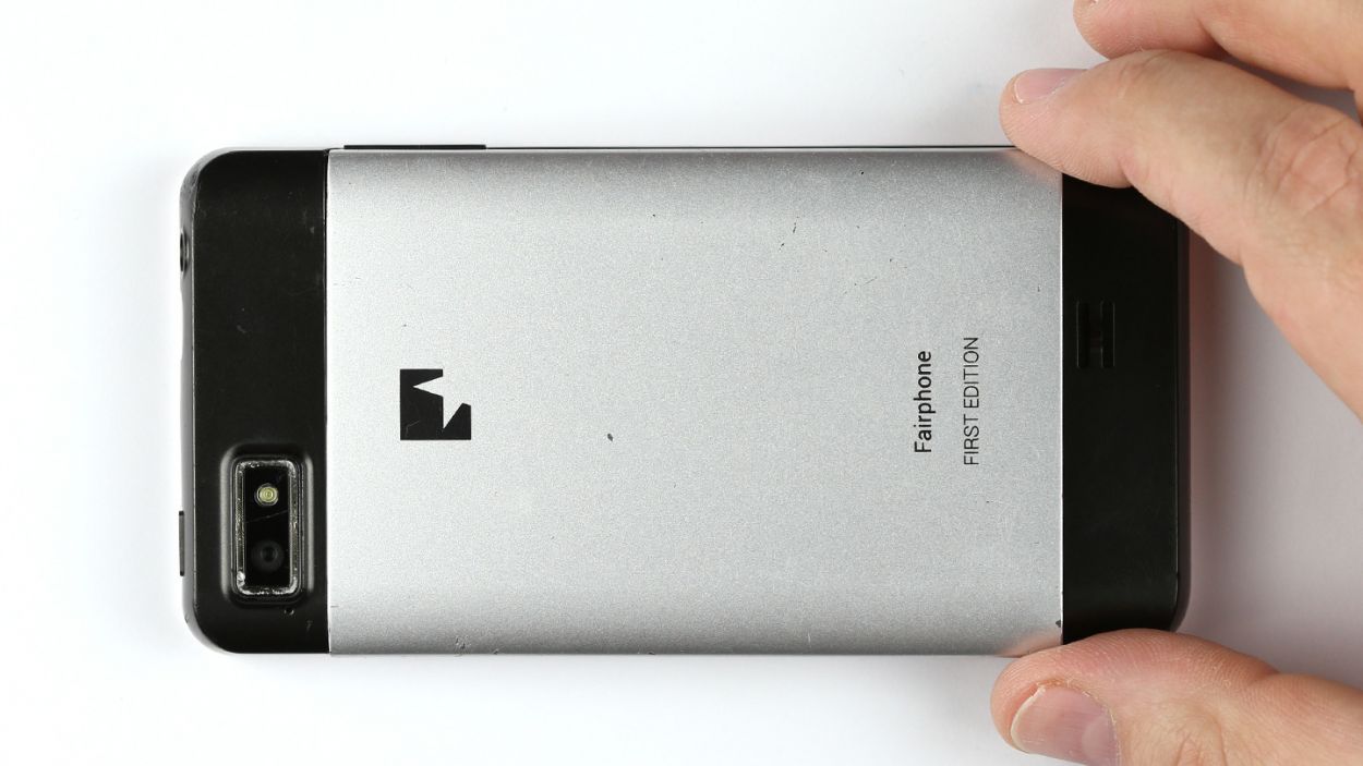
– Hey there! Let’s pop that back cover off. See that little notch on your Fairphone? Use your finger to gently pry it open. It’s easier than it looks!
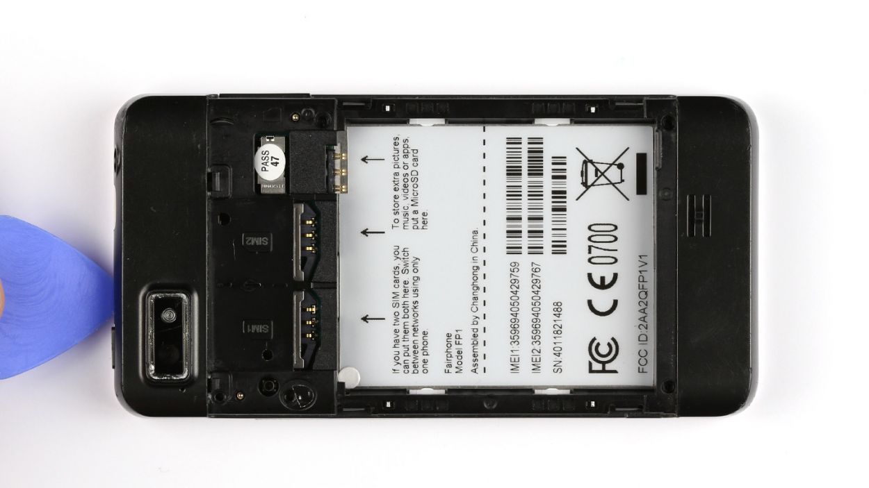
– Sweet! Now just lift the back cover right off. You’re doing awesome!

Step 3
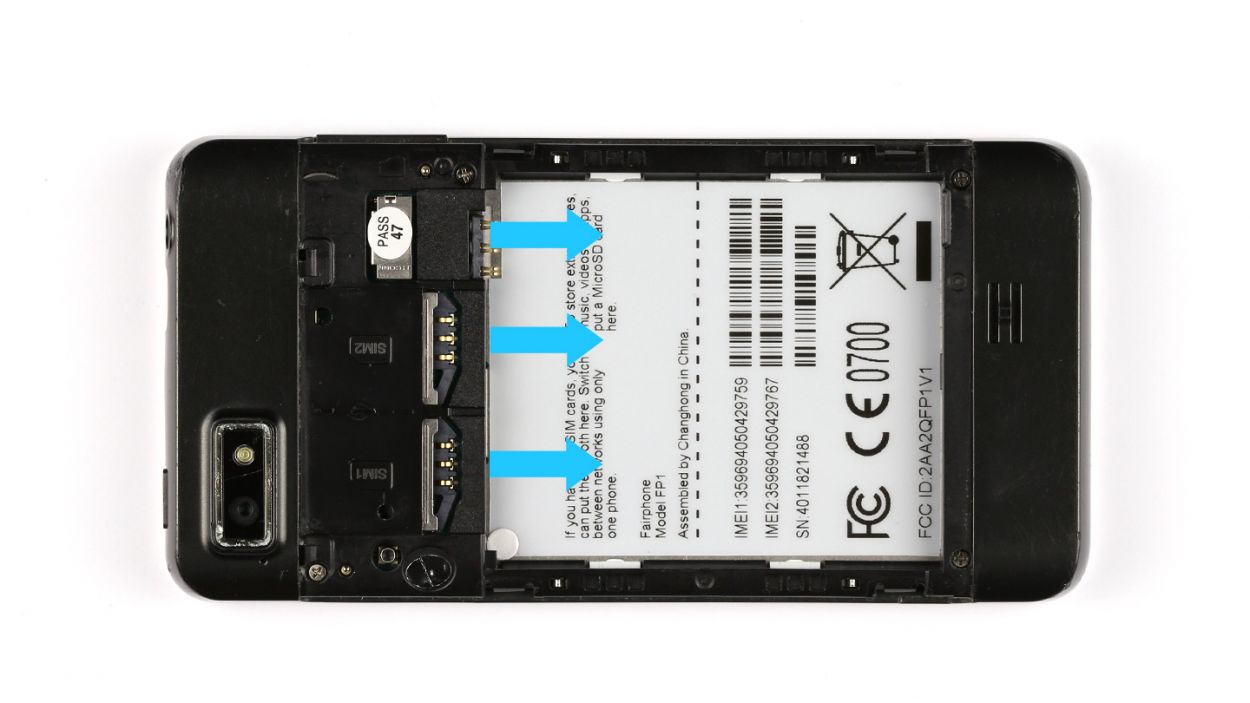
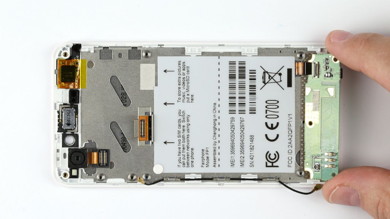
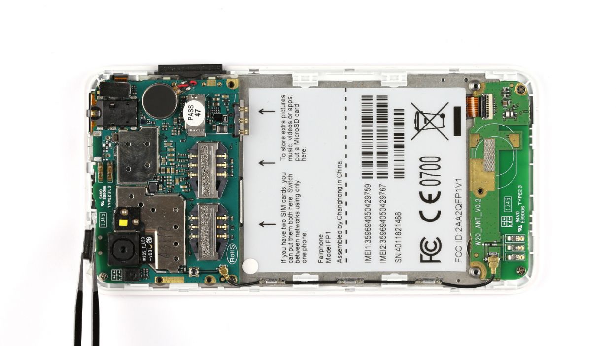
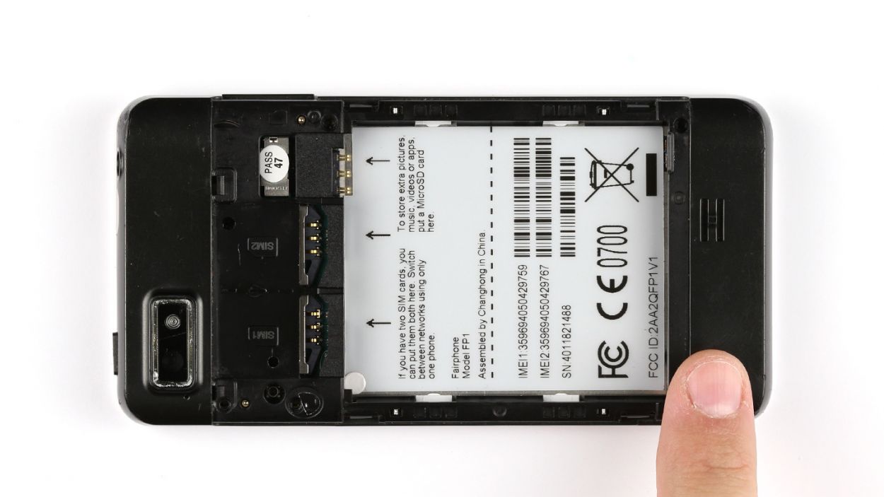
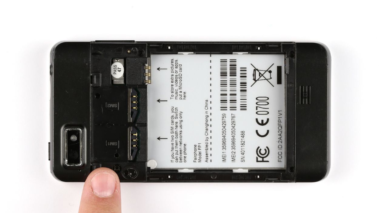
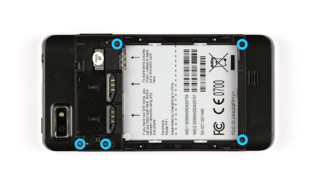
– Pop out the SIM cards and the microSD card like a pro!
Step 4

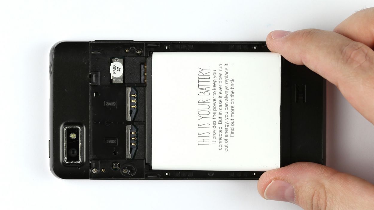
– Time to get this party started! Pop off that seal and let’s get to the good stuff!
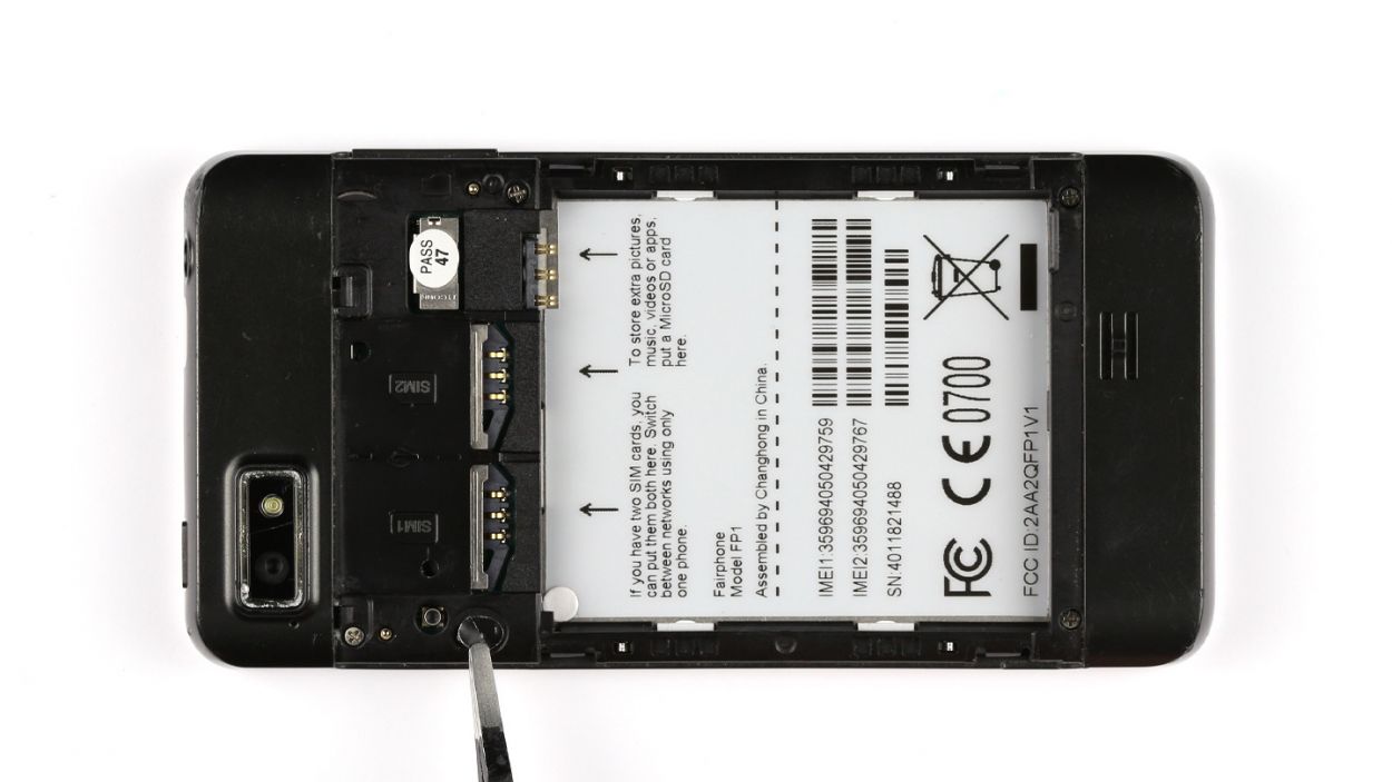
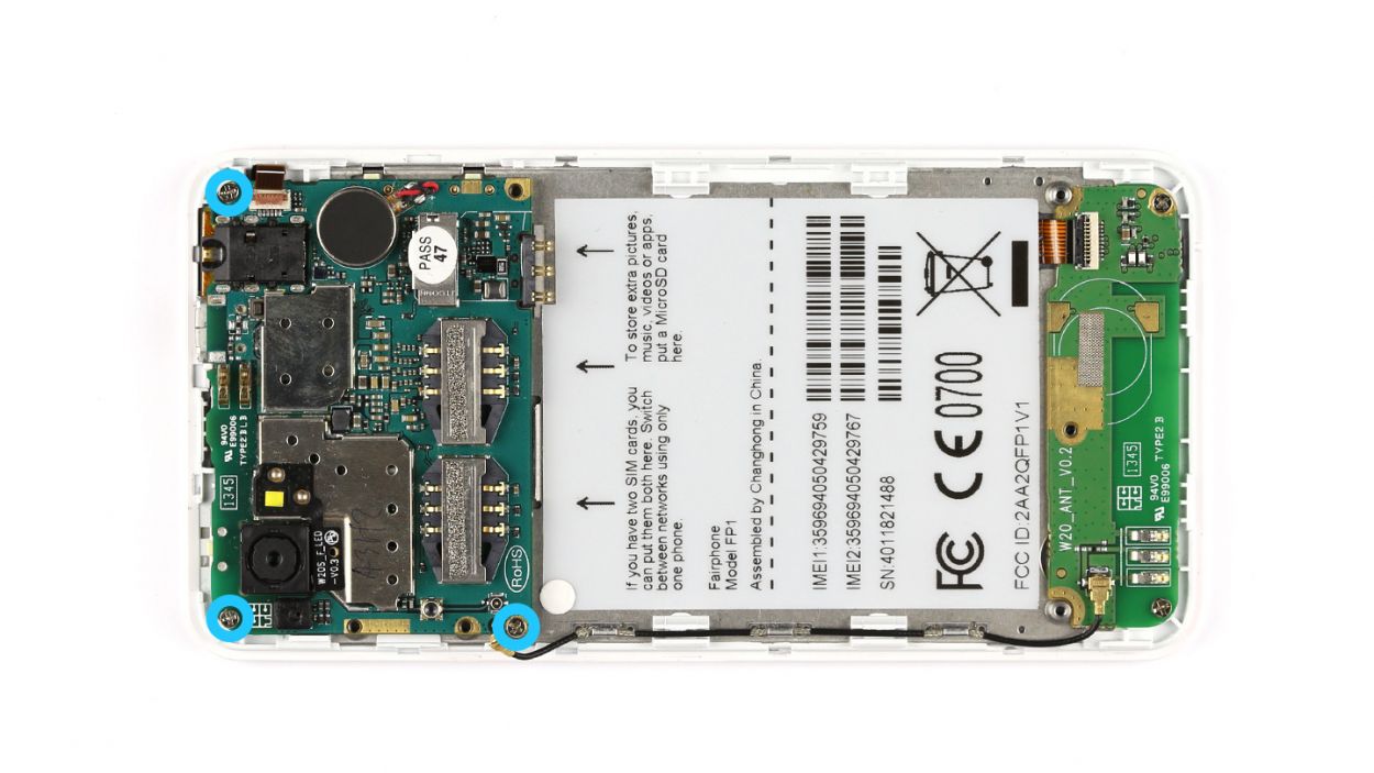
– Now, let’s get those screws out of the way! You’ll need to remove 5 x 3.9 mm Phillips screws. Ready, set, go!


Step 7
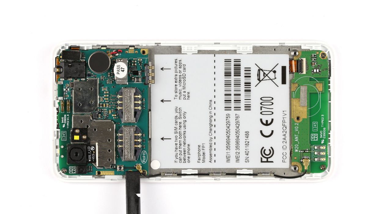

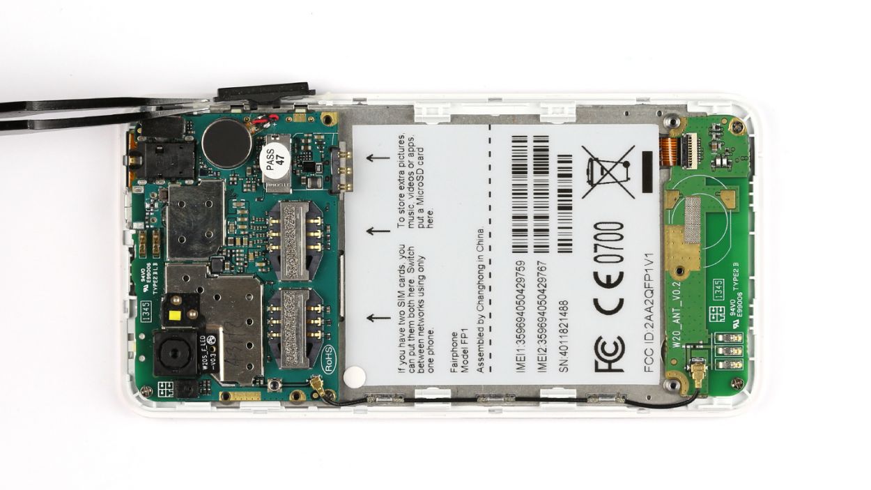
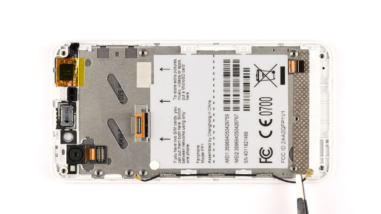
– Grab your trusty spudger and gently pry off the antenna cable from the logic board. You’ve got this!
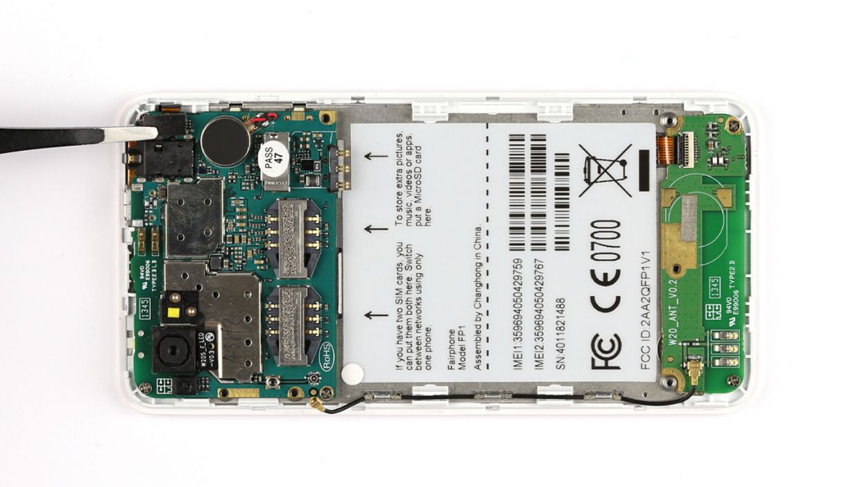
– With a steady hand, use your tweezers to delicately lift the cover off the sensor contact. Easy peasy!
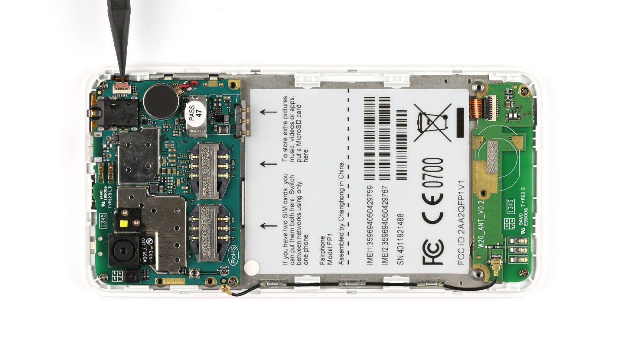
– Time to work your magic! Use the spudger to free the flexible flat cable. You’re doing great!
– Carefully disconnect that flexible flat cable from the logic board. Almost there!
Step 8


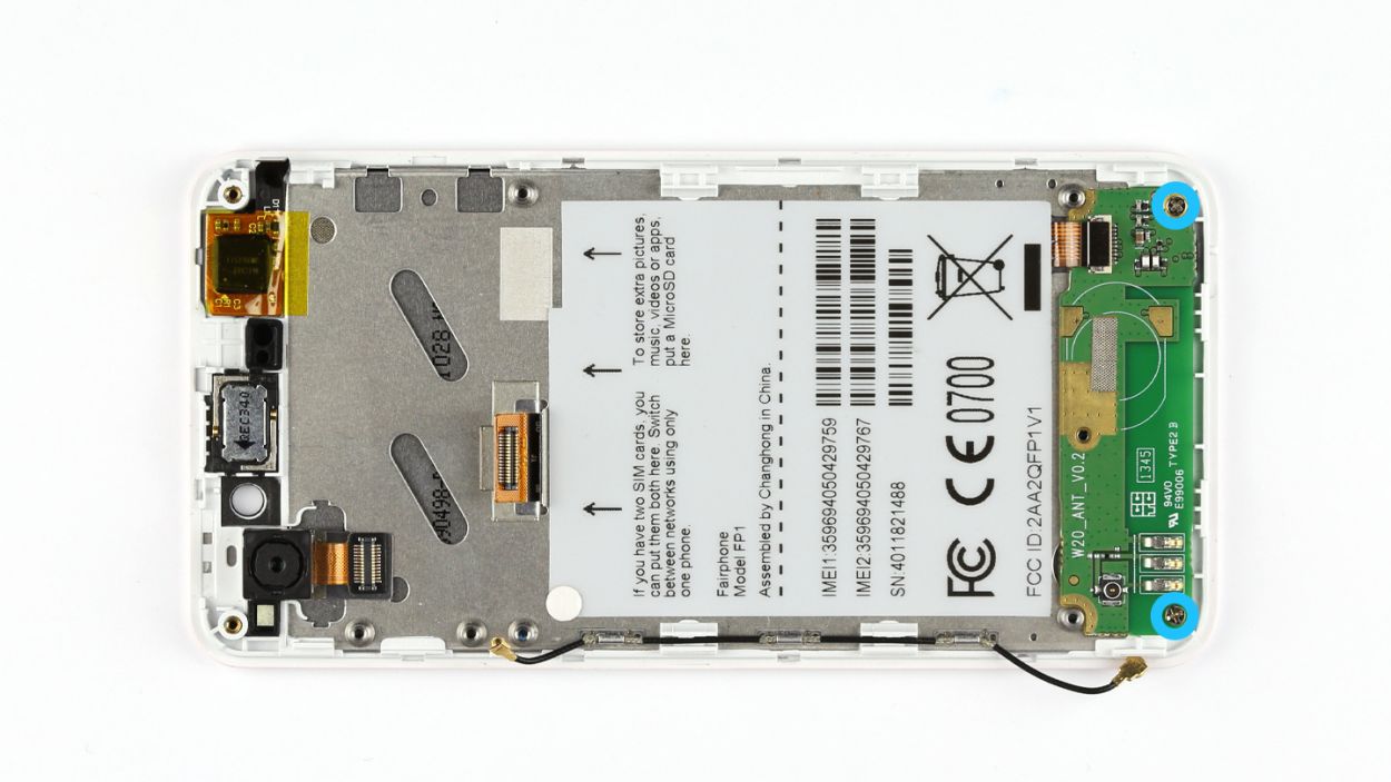
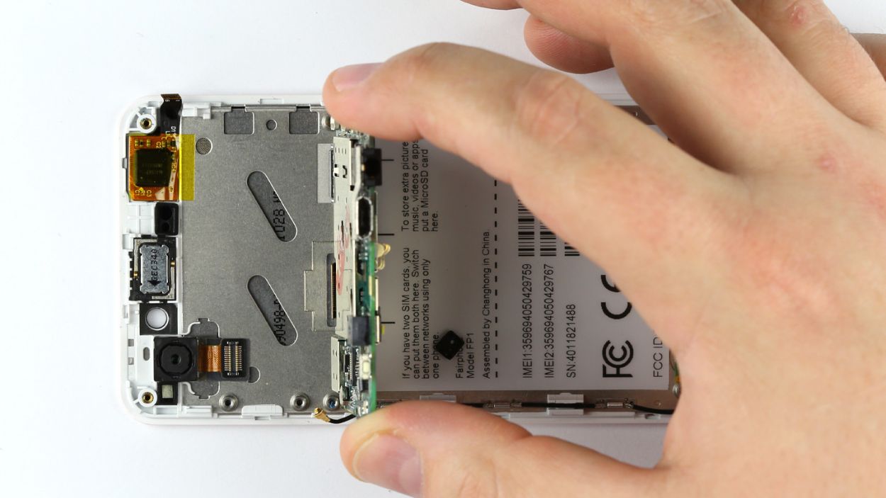
– Start by unscrewing those three Phillips screws—3 x 2.2 mm Phillips screws, to be exact. You’ve got this!
– Gently lift the logic board, but hang tight; it’s not time to take it out just yet since it’s still connected to the display.
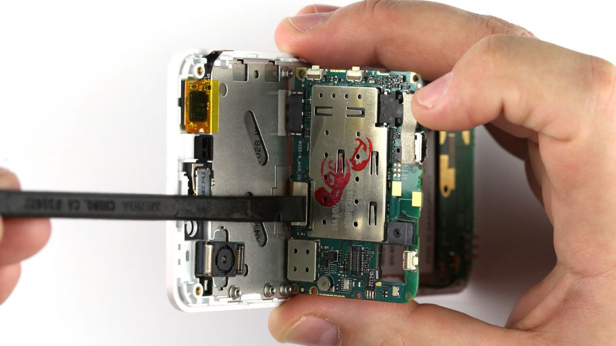
– Now, give that logic board a friendly tilt upwards by 90° so you can reveal the display connection hiding beneath it.
– Use your trusty spudger to disconnect the display contact—you’re doing awesome!
Step 9


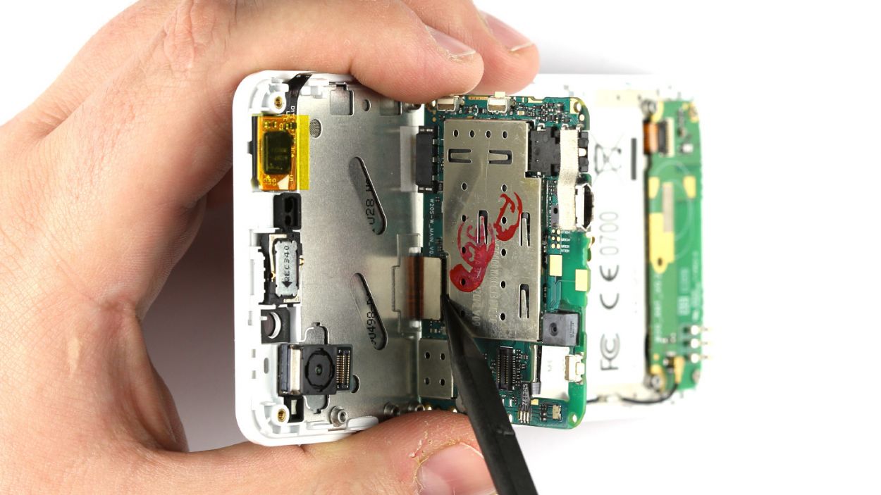
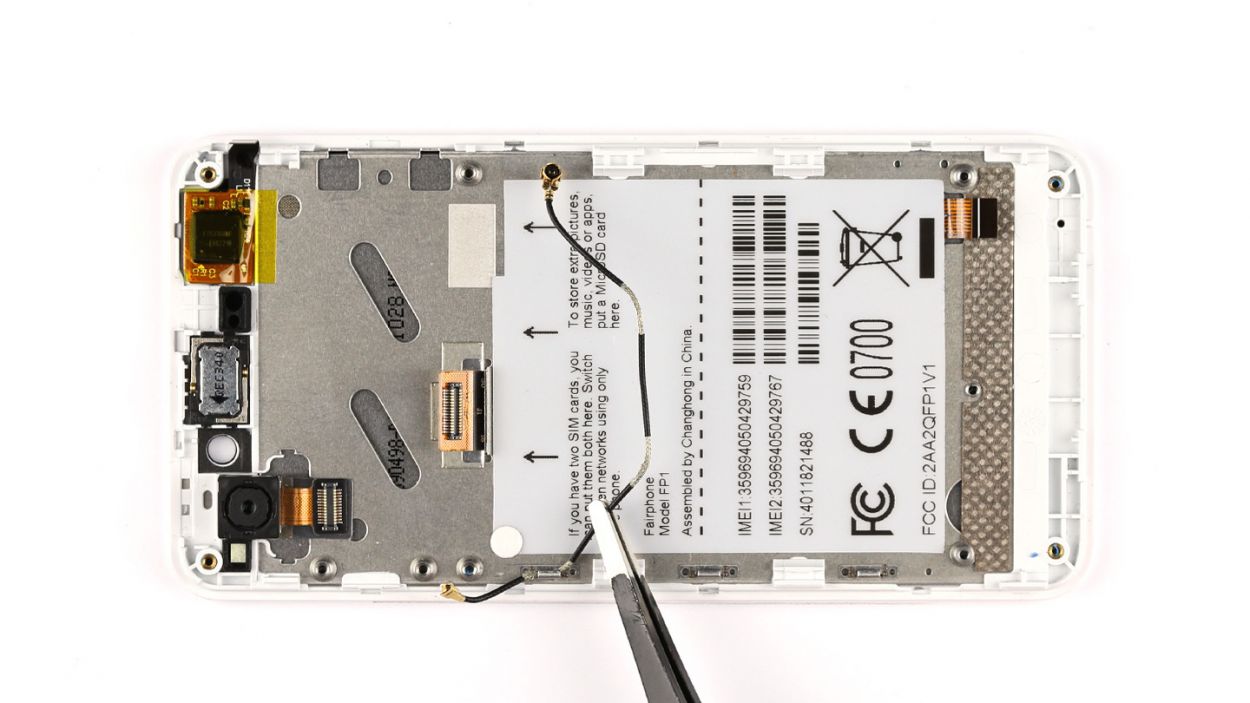
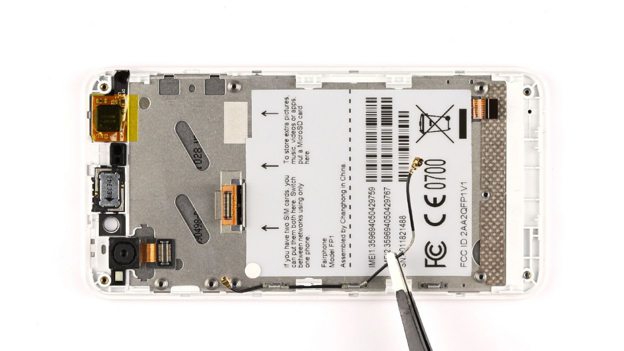
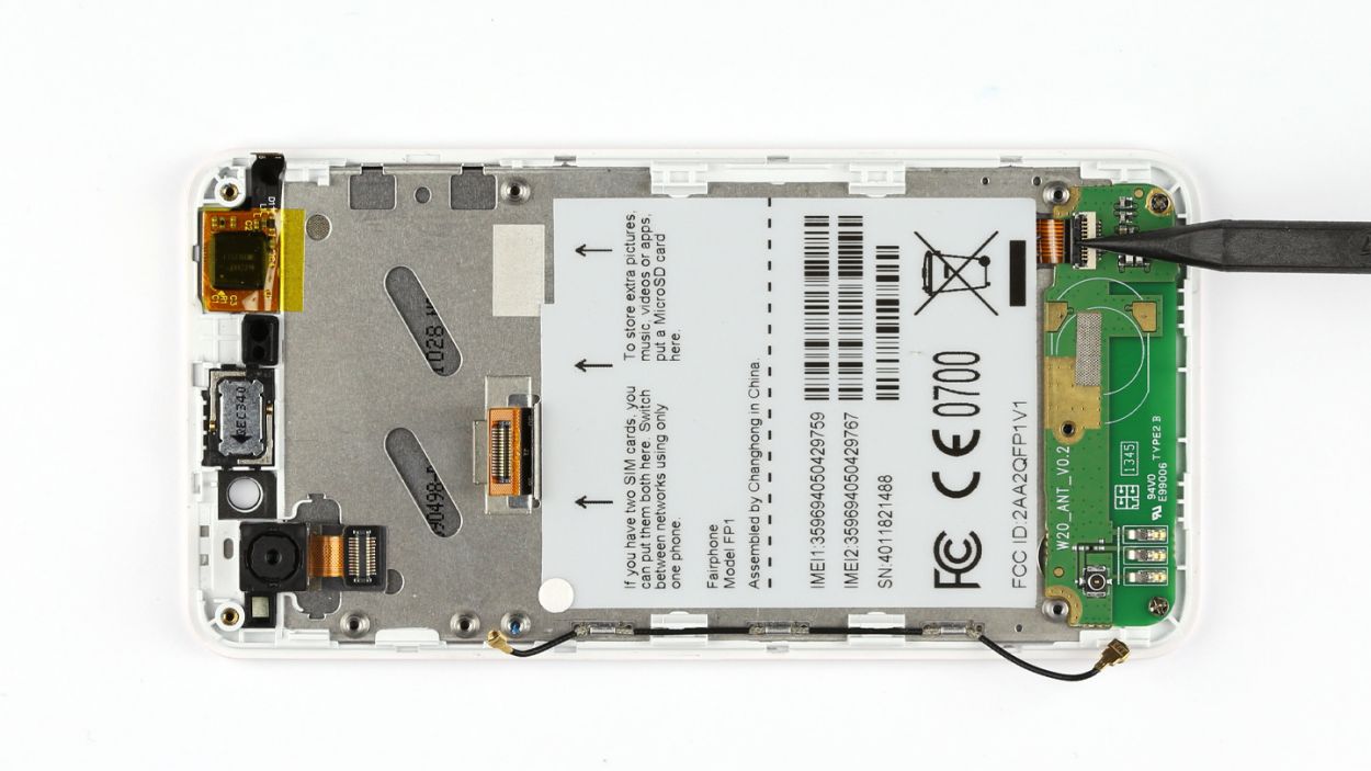
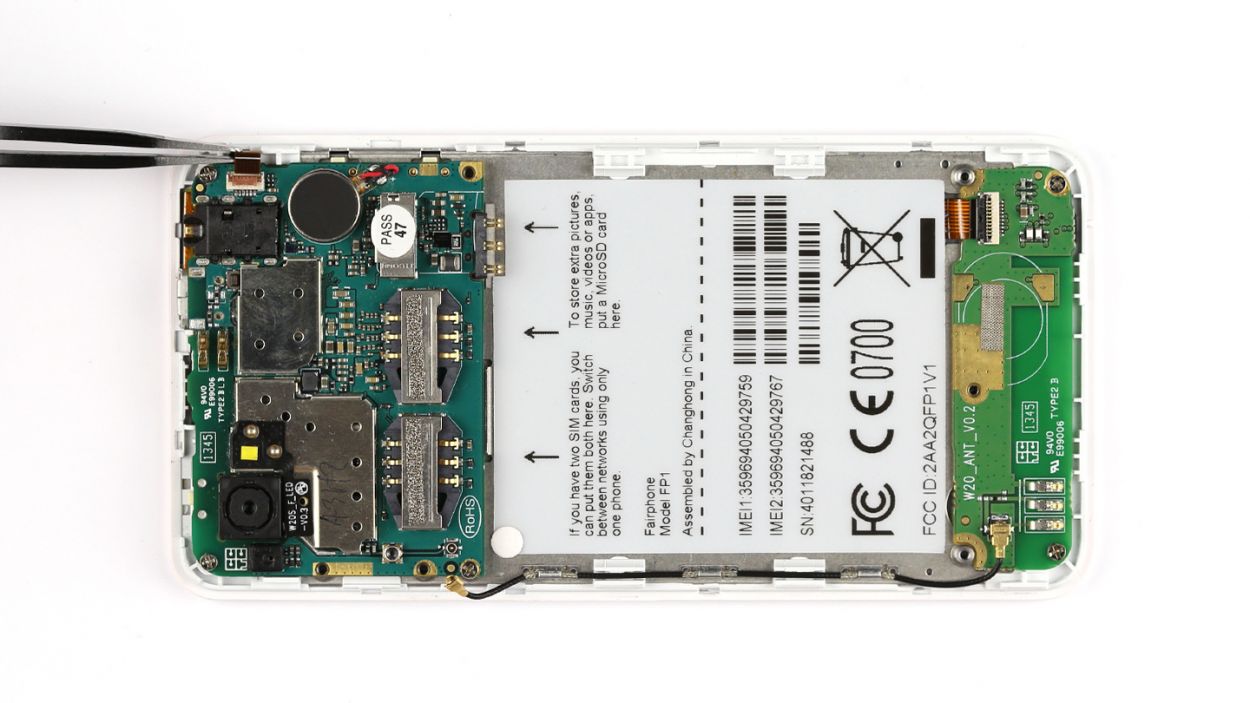
– First things first, gently unplug the antenna cable from the sub-board. Easy peasy!
– Next up, grab your trusty spudger and pop open the locking mechanism of the flexible flat cable. Then, with a steady hand, use your tweezers to disconnect that cable from the connector. You’ve got this!
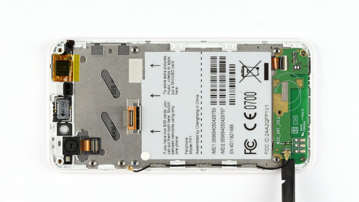
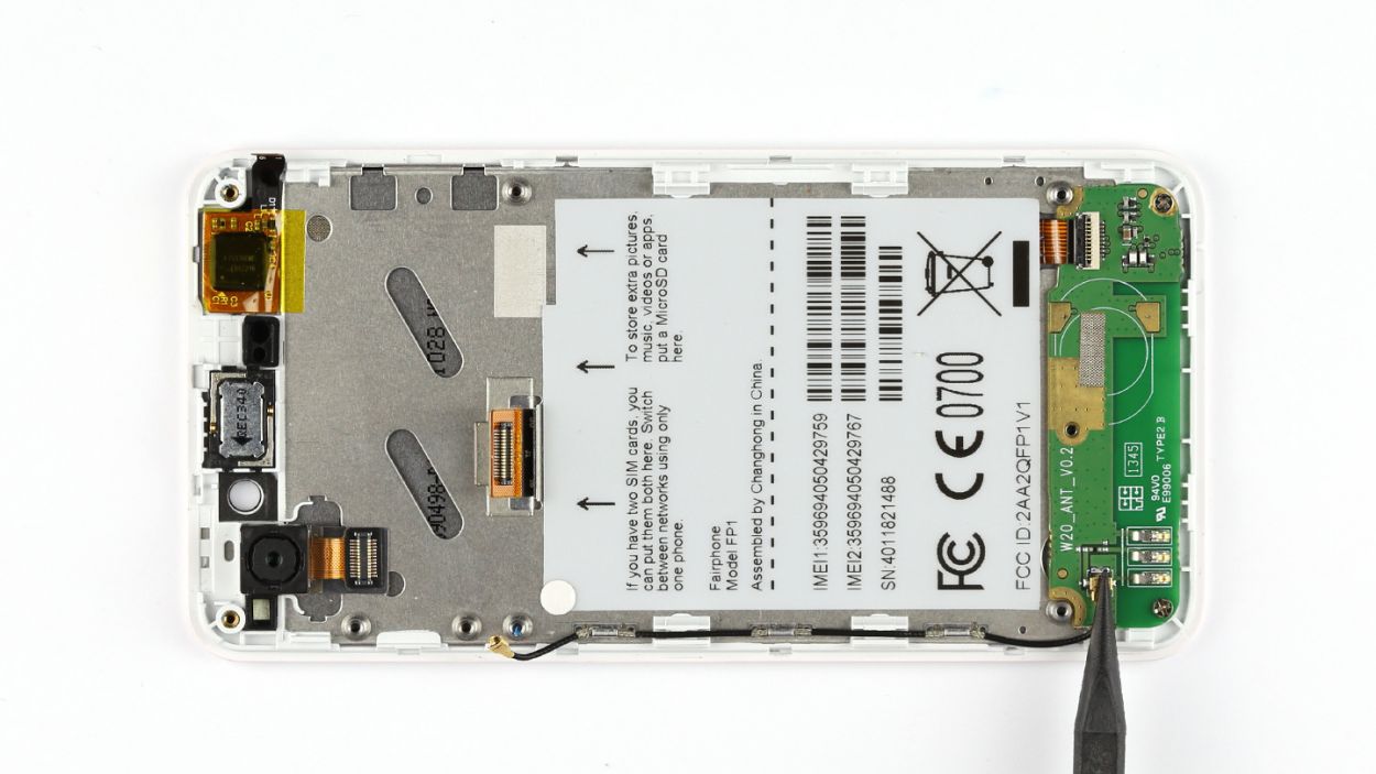
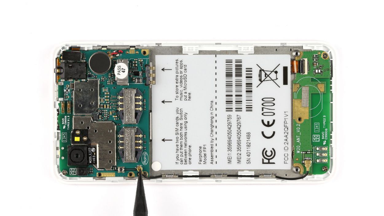
– Now, it’s time to tackle those screws! Remove the two Phillips screws, each measuring 3.9 mm. Just a couple of twists and you’re golden!
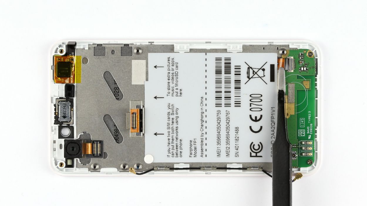
– Finally, carefully lift the sub-board out of the display frame. You’re almost there!


Step 11

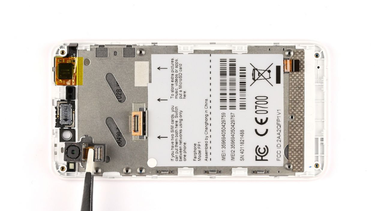
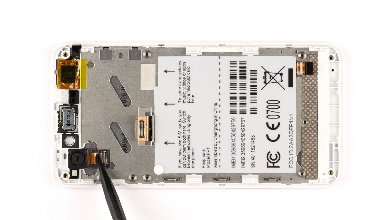
– The rear-facing camera is snugly glued to the display frame. Grab your trusty steel spatula and gently pry it loose.
– Now, go ahead and lift out the camera.
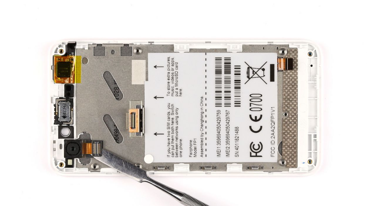
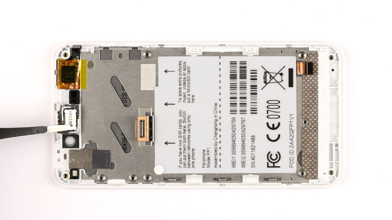
Step 12
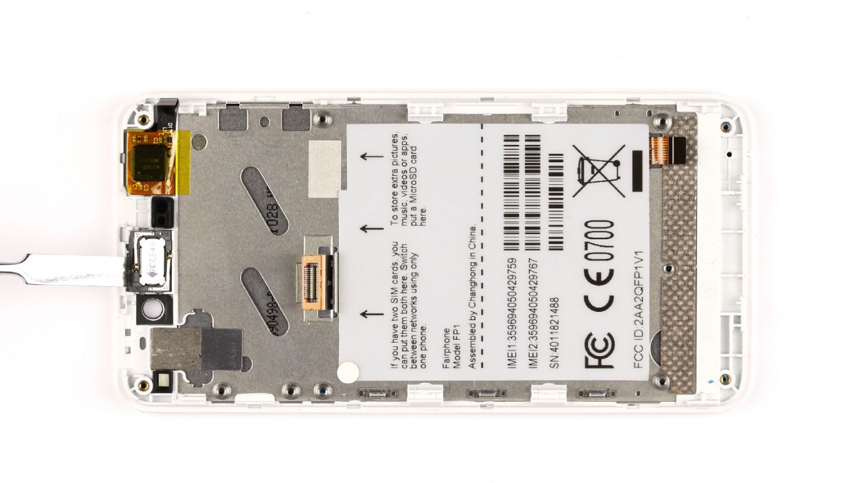

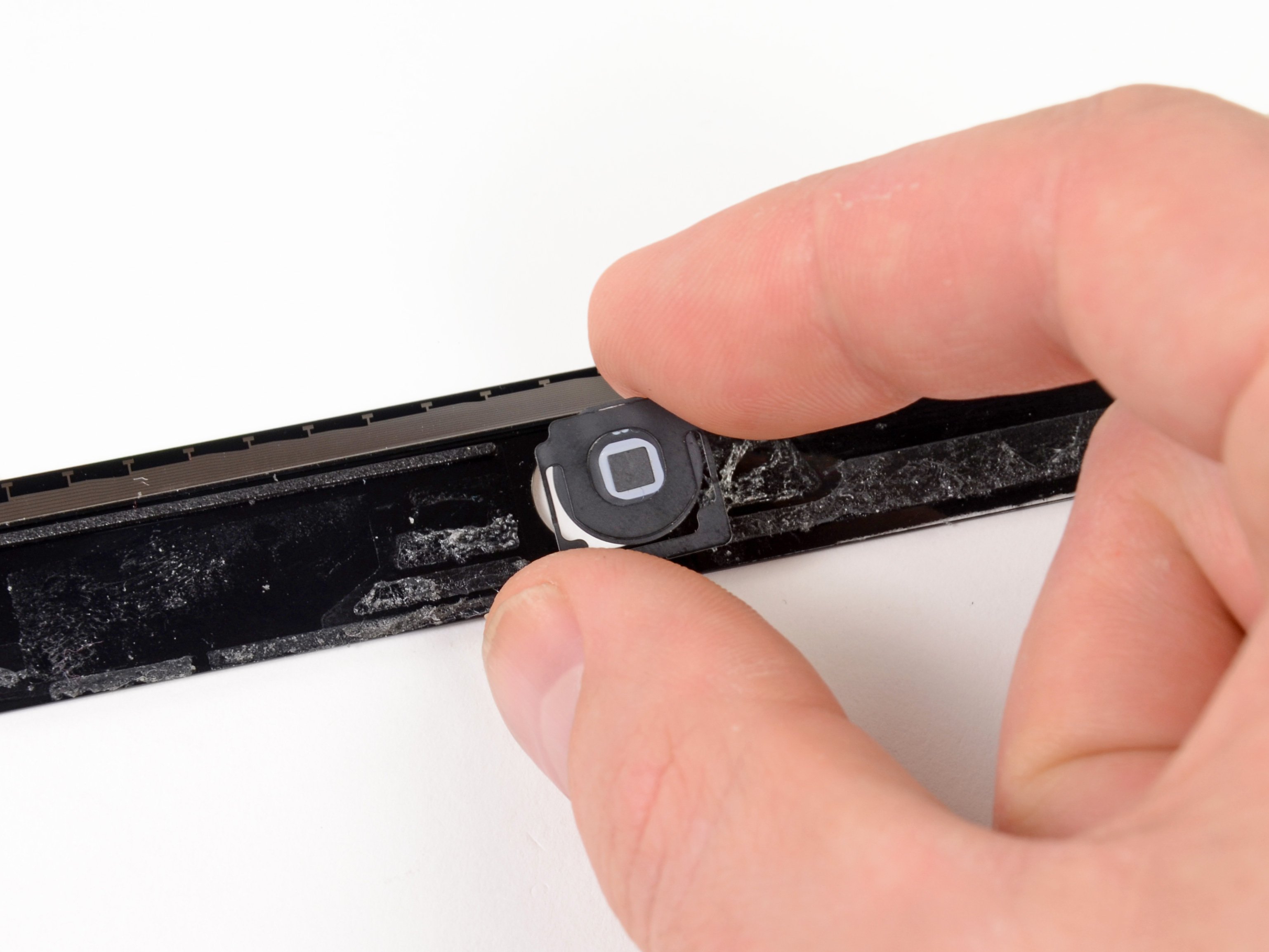
– The earpiece is glued to the display frame. Using the steel spatula, carefully detach the earpiece.
Step 14
– Put the rear-facing camera back where it belongs, giving it a snug fit on the display
– Give it a little push to make sure it’s secure, all set!
Step 16


– Get ready to breathe new life into your device by attaching the sub-board to the display frame! Position the sub-board onto the display frame, making sure it clicks comfortably into place.
– Time to get the screws in! Secure the sub-board to the display frame using the two Phillips screws provided. Tighten them snugly, but don’t overtighten – we want it to be secure, not stuck.
– The final touch – connect that flexible flat cable to the sub-board and lock it into place. Easy peasy!
– Last but not least, attach the antenna cable to the sub-board and you’re all set to rock! If you need help, you can always schedule a repair.
Step 17


– Angle the logic board at a crisp 90° over the display!
– Time to connect that display to the logic board; let’s make them best friends!
– Gently place the logic board back into its cozy spot on the display frame.
– Now, let’s secure it all in place with three Phillips screws – specifically, the 3 x 2.2 mm kind!
Step 18


– First up, let’s connect that flexible flat sensor cable to the logic board. It’s like giving your device a little hug!
– Next, make sure to lock that plug connection in place. We want it to feel secure and happy.
– Now, it’s time to put the cover back on. Think of it as tucking your device in for a cozy night.
– Finally, connect the antenna cable to the logic board. It’s like giving your device a boost to stay connected!


Step 21

– Use the five Phillips screws to attach the chassis.5 x 3.9 mm Phillips screws
– Put the seal back on.
Step 22

– Alright, you’ve made it to the final stretch! Now it’s time to reinstall your SIM cards and microSD card. Easy peasy, right this way.

Step 24

– Put the back cover back on. Make sure the two tabs on the back cover hook into the chassis.
– Press the back cover on until you hear it click into place.