DIY Guide to Replace Fairphone 1 Screen
Duration: 45 min.
Steps: 25 Steps
Welcome to our guide for giving your Fairphone a shiny new display! If your glass is cracked, your touchscreen has gone on strike, or the LCD is throwing a tantrum by staying black or flickering, this repair is just for you! Let’s get started and bring your device back to life!
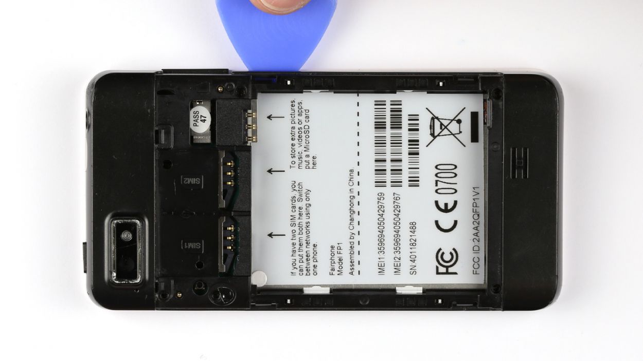
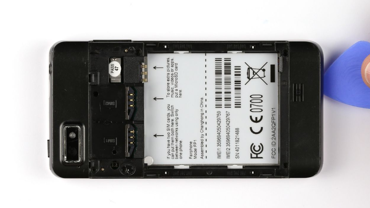
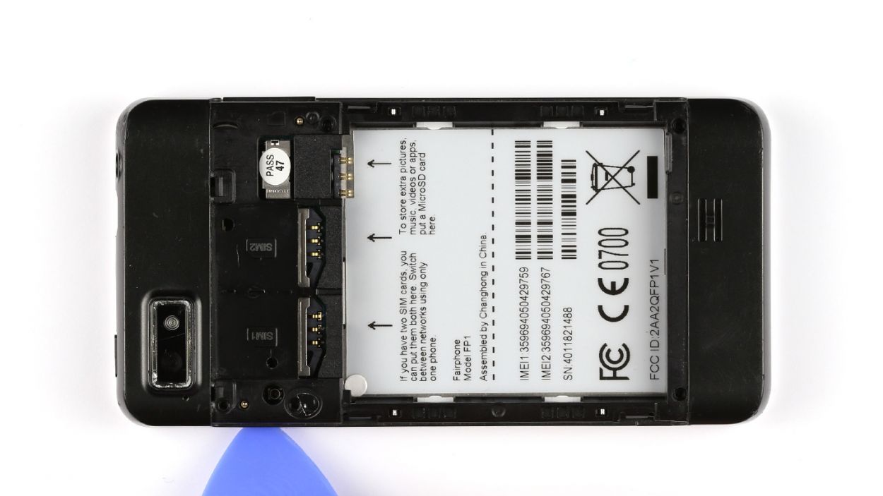
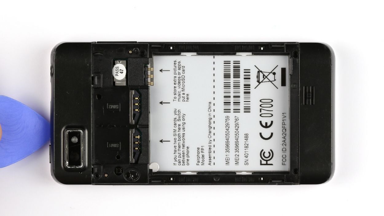
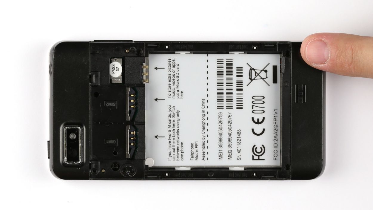
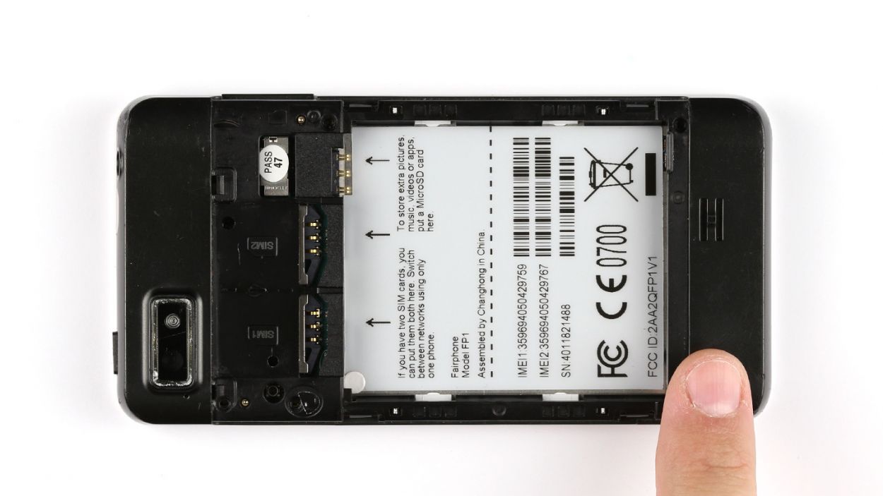
Step 1
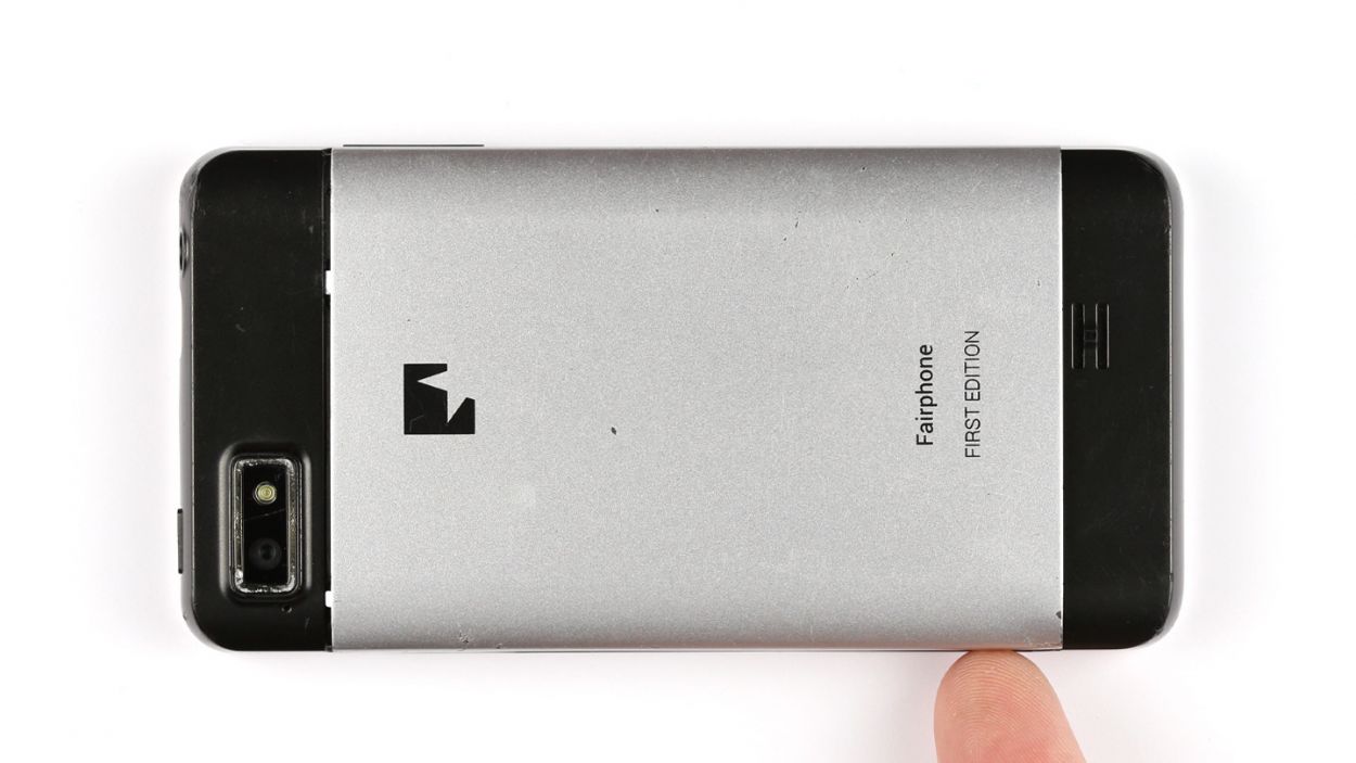

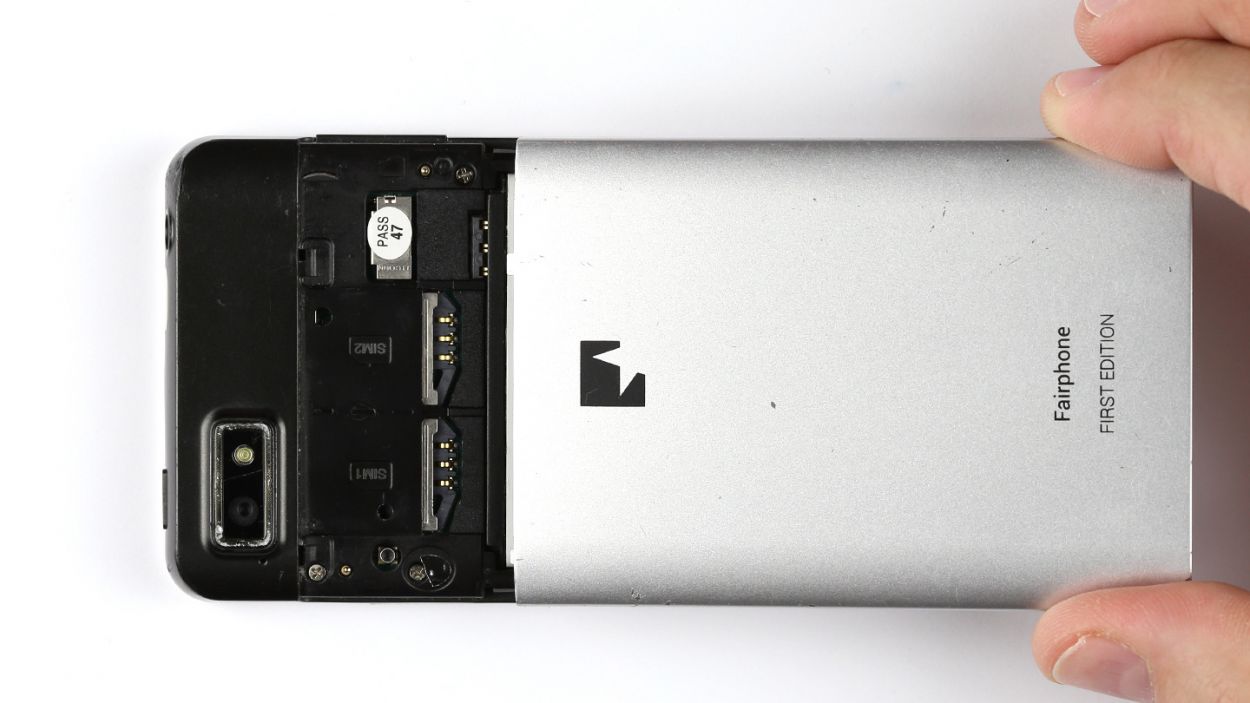
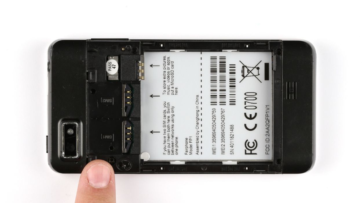
– Gently lift the back cover using your finger to pop it off the smartphone. There’s a handy little groove on the side of the Fairphone just for this!
– Carefully take the back cover off the device.

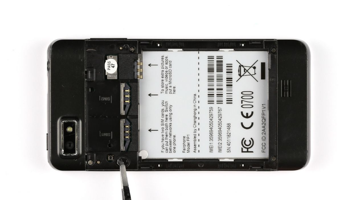
Step 3
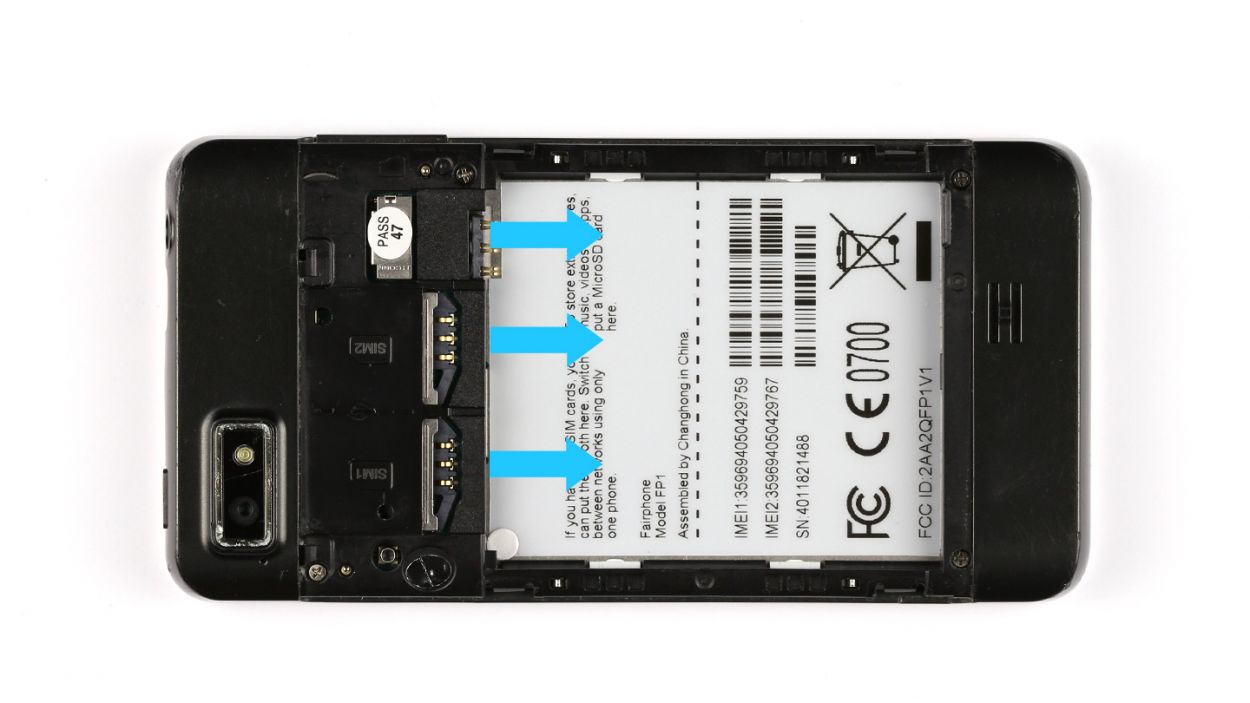
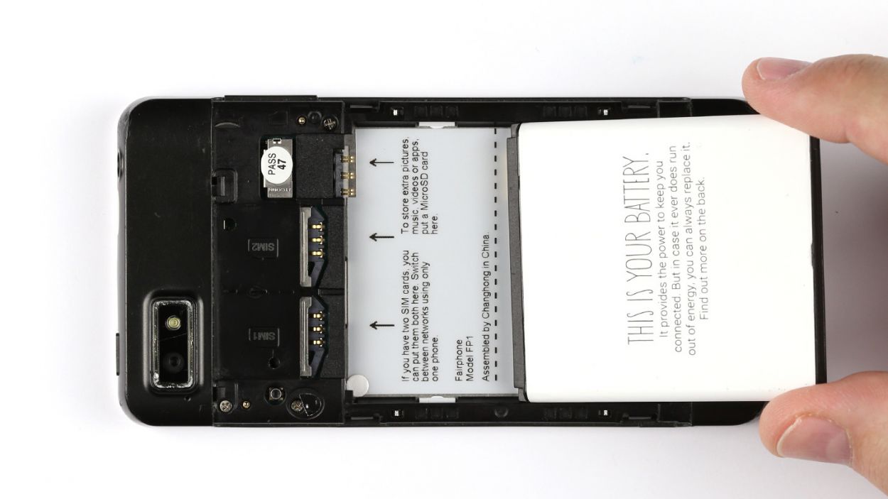
– Time to liberate the SIM cards and microSD card from their cozy little home. Get them out and let’s keep moving forward!
Step 4

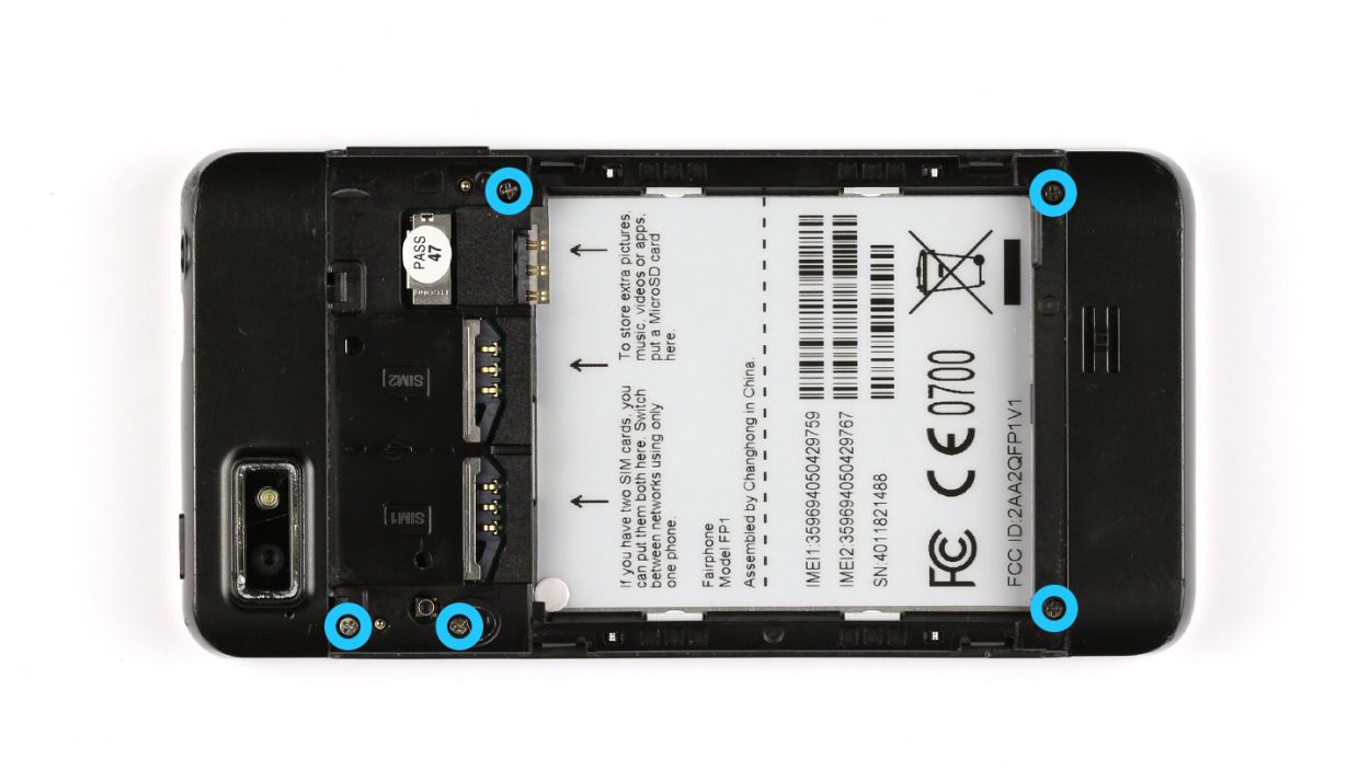
– Time to break out the toolkit! Remove the seal to gain access to those pesky screws.
– Seriously, it’s just 5 x 3.9 mm Phillips screws – not that complicated. Get rid of ’em and proceed!


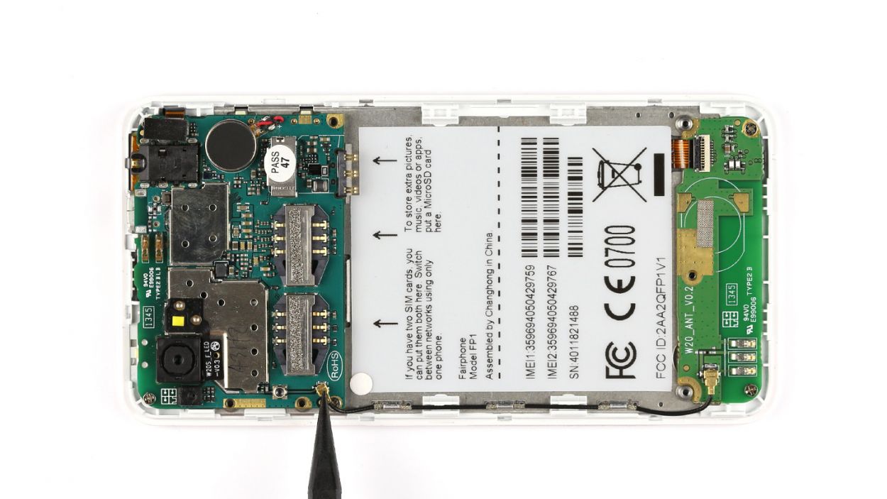
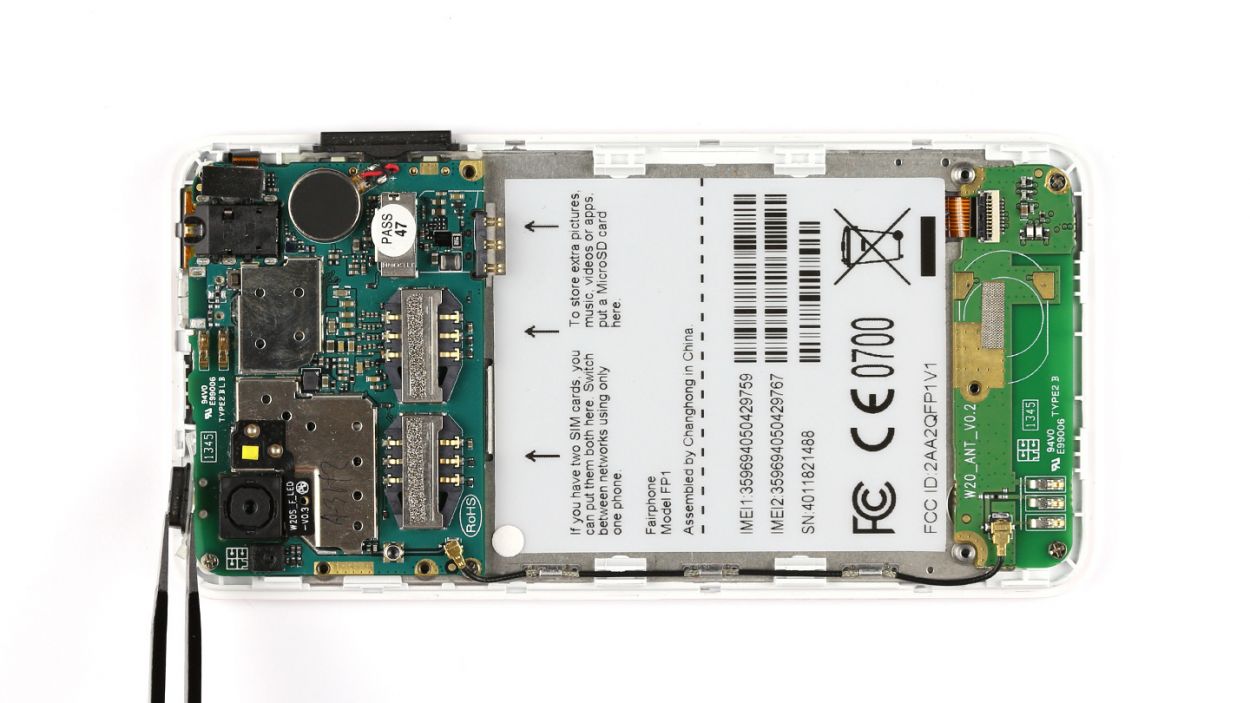
Step 7
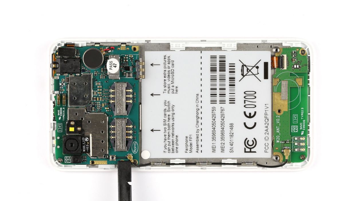

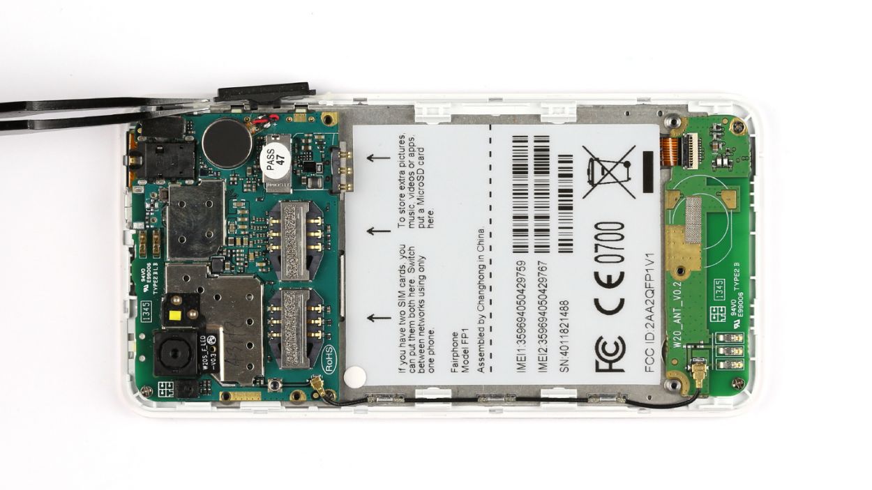
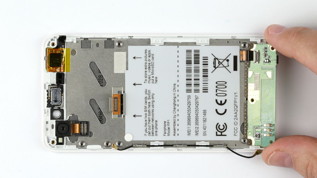
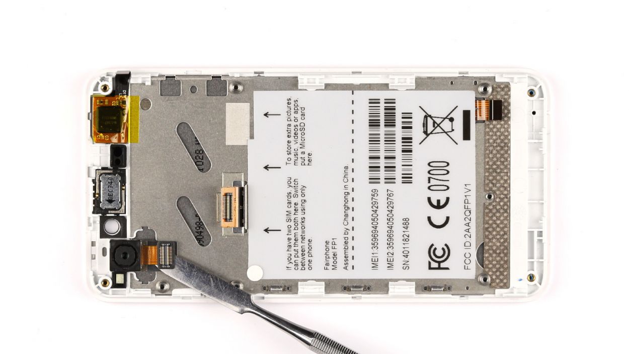
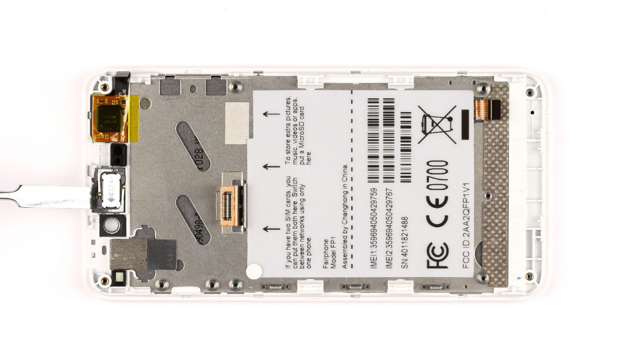
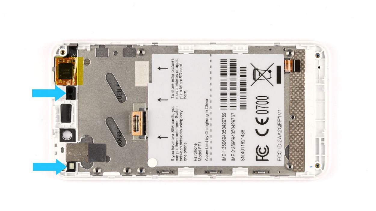
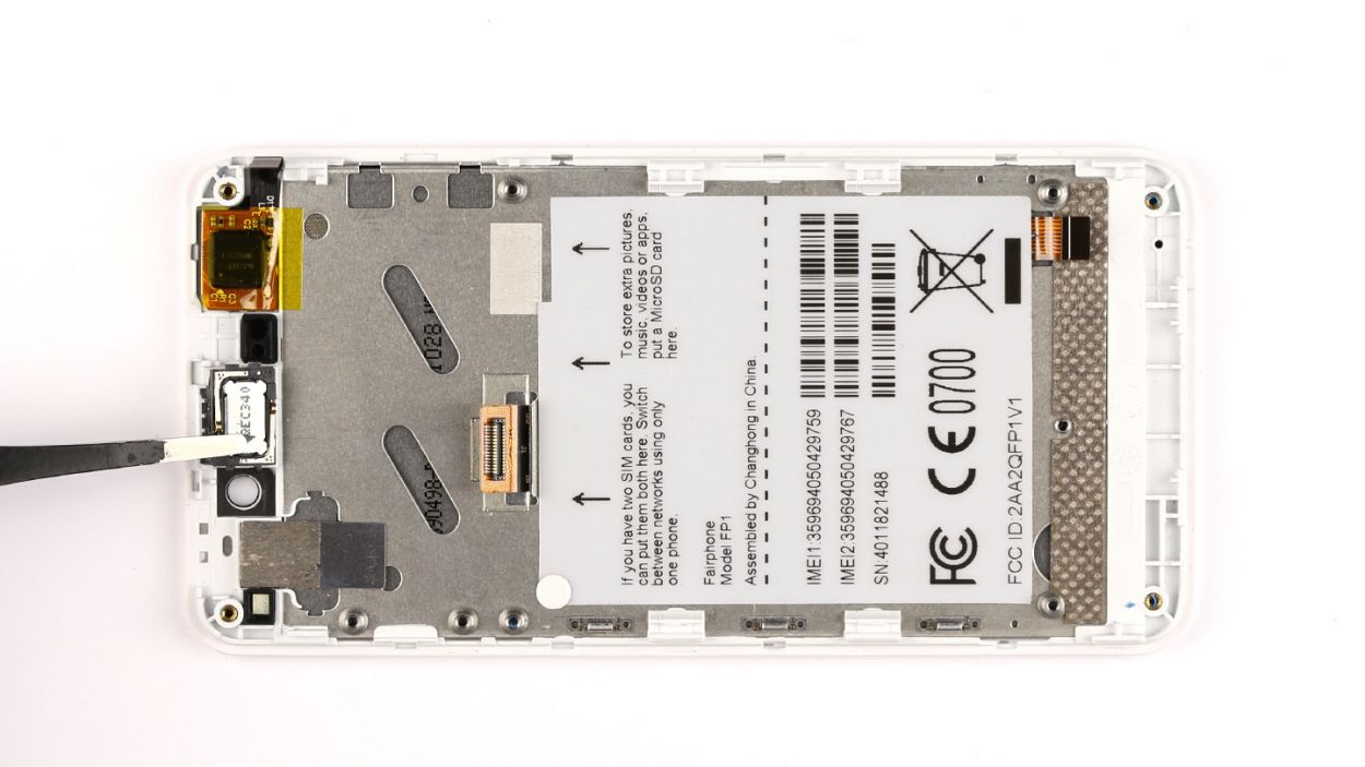
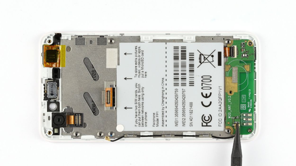
– Grab your trusty spudger and gently pry off the antenna cable from the logic board. You’ve got this!
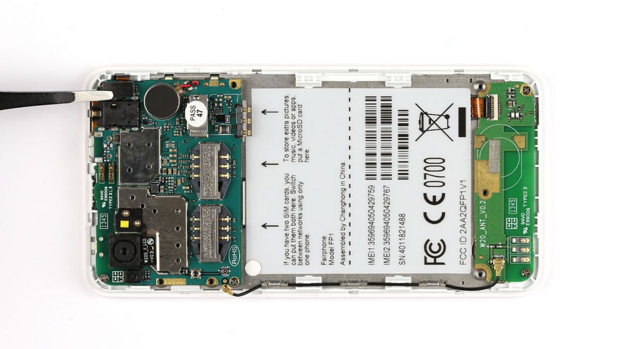
– With a steady hand, use tweezers to delicately lift the cover off the sensor contact. Easy peasy!
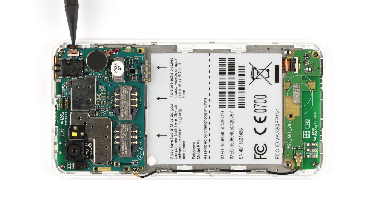
– Time to work your magic with the spudger again—let’s release that flexible flat cable!
– Now, carefully disconnect the flexible flat cable from the logic board. You’re doing great!
Step 8
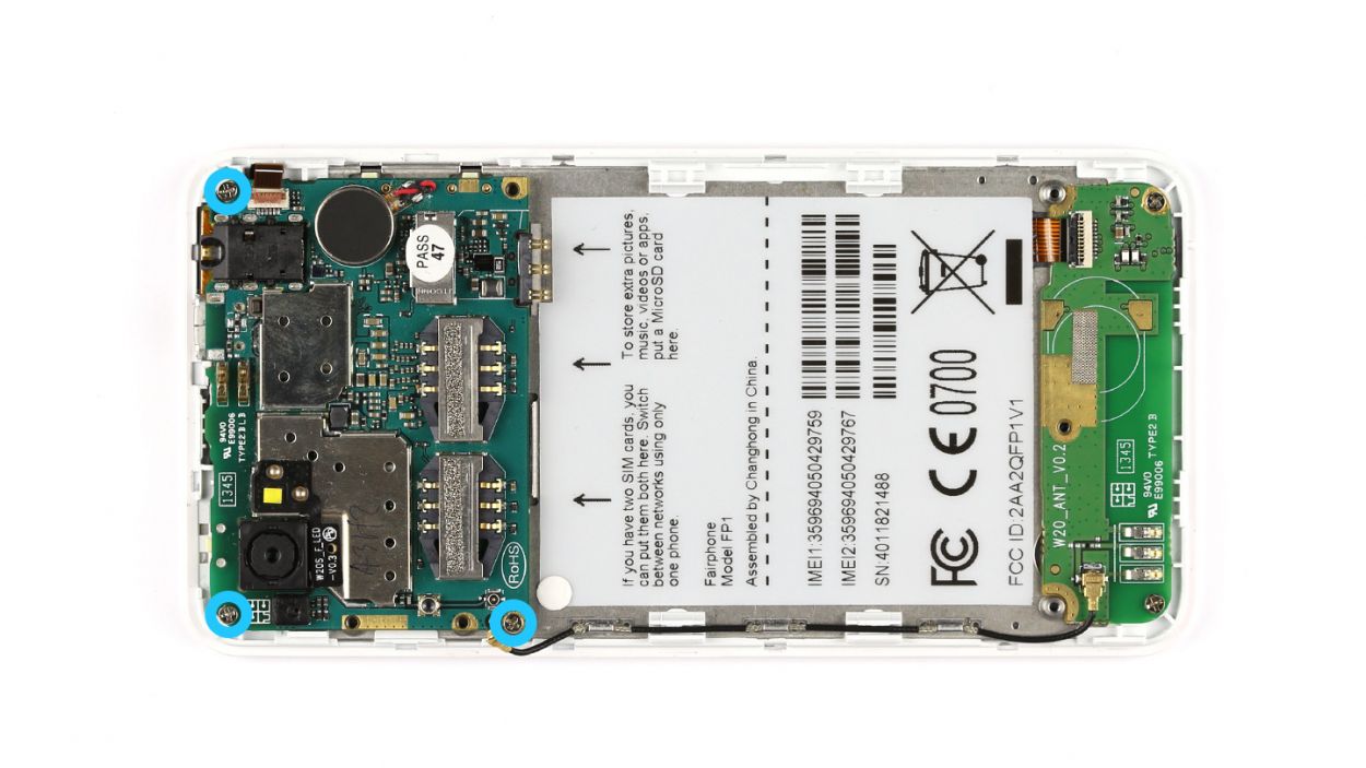


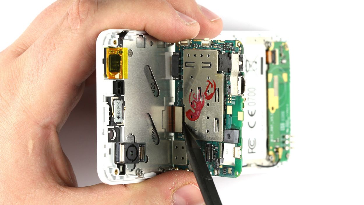
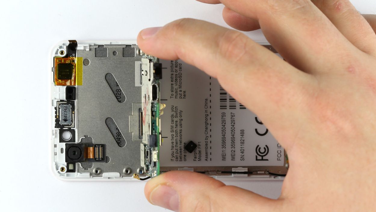
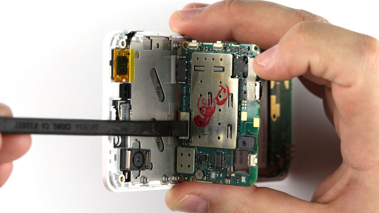
– Time to get started! Remove the three Phillips screws (3 x 2.2 mm Phillips screws) – it’s like taking off a hat, easy peasy!
– Next, lift the logic board, but don’t remove it yet, superhero! It’s still connected to the bottom of the display, keeping the magic alive.
– Now, tilt that logic board upwards by 90°, so you can get to the display connection underneath. This is like setting up a miniature workshop in here!
– Last but not least, use your trusty spudger to disconnect the display contact. And voilà! You’re getting closer to saving the day (and your device)!
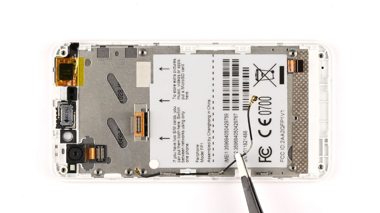
Step 9
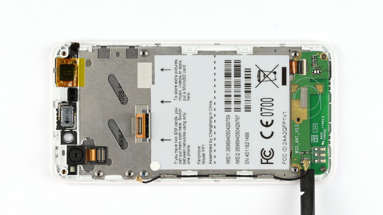


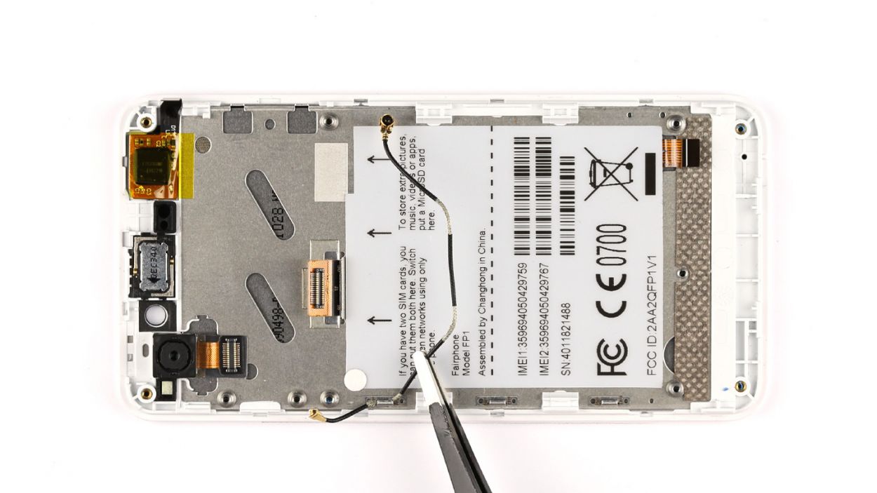
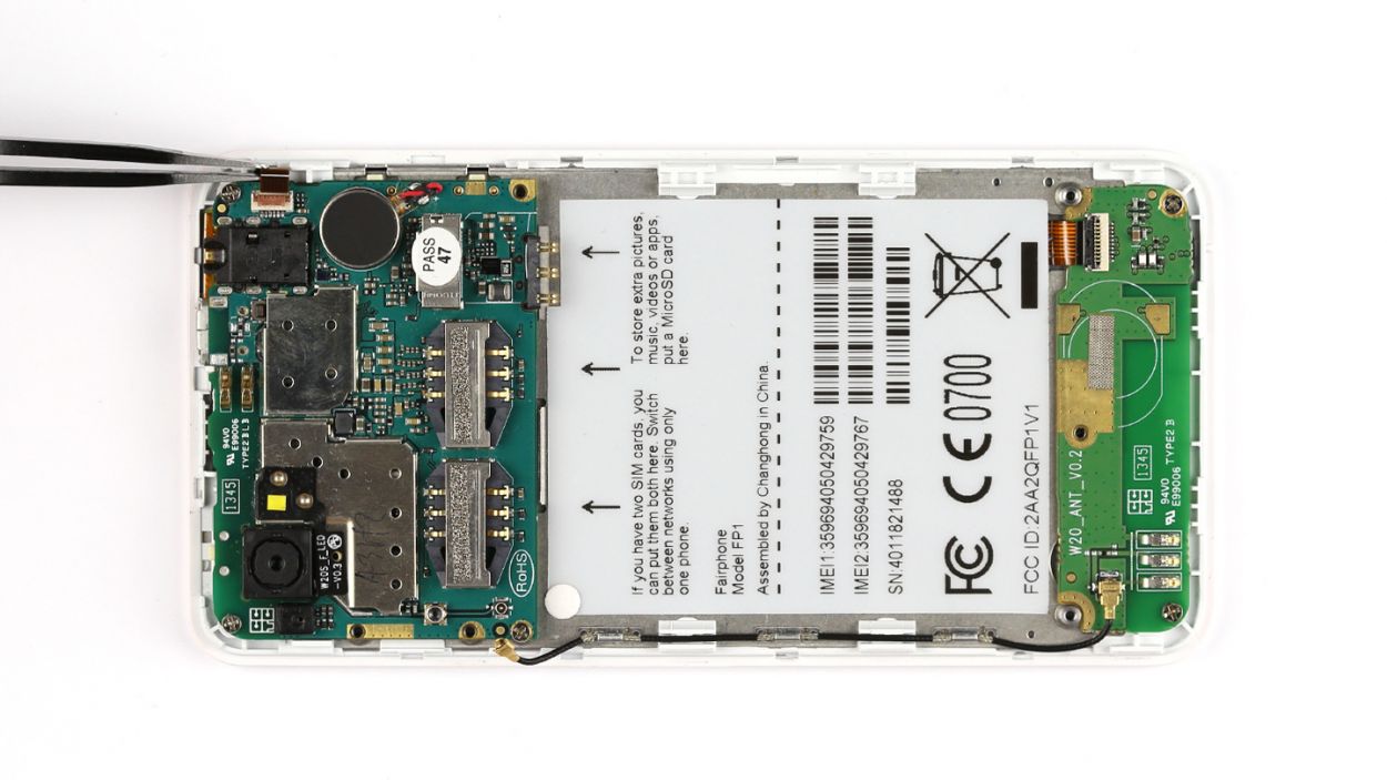
– First things first, gently unplug the antenna cable from the sub-board. You’ve got this!
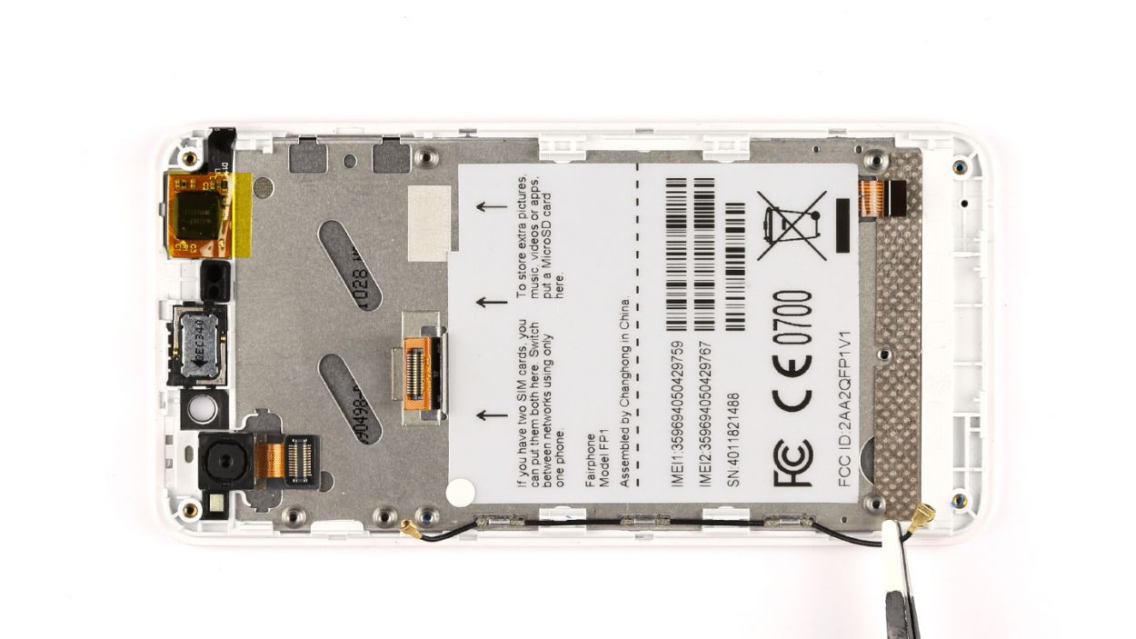
– Next up, grab your trusty spudger and carefully pop open the locking mechanism of the flexible flat cable. Then, with a steady hand, use the tweezers to disconnect that cable from the connector. Easy peasy!
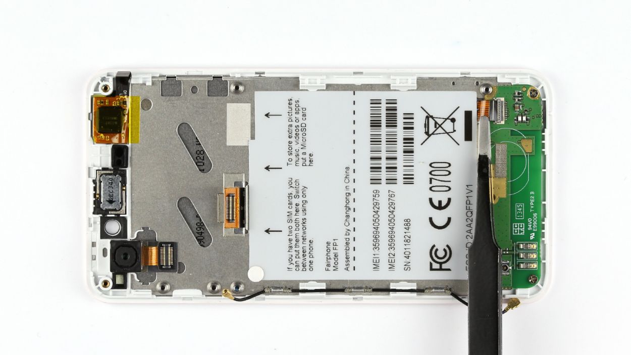
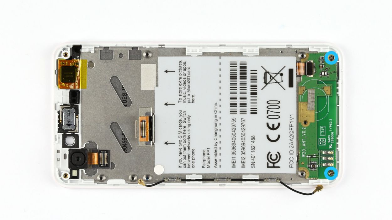
– Now, it’s time to remove those two Phillips screws. We’re talking about 2 x 3.9 mm Phillips screws here. Just a couple of twists and you’re golden!
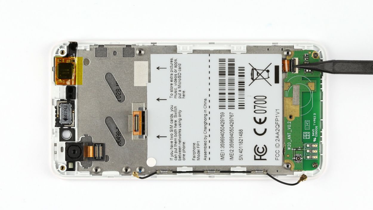
– Finally, lift the sub-board out of the display frame. You’re almost there!


Step 11

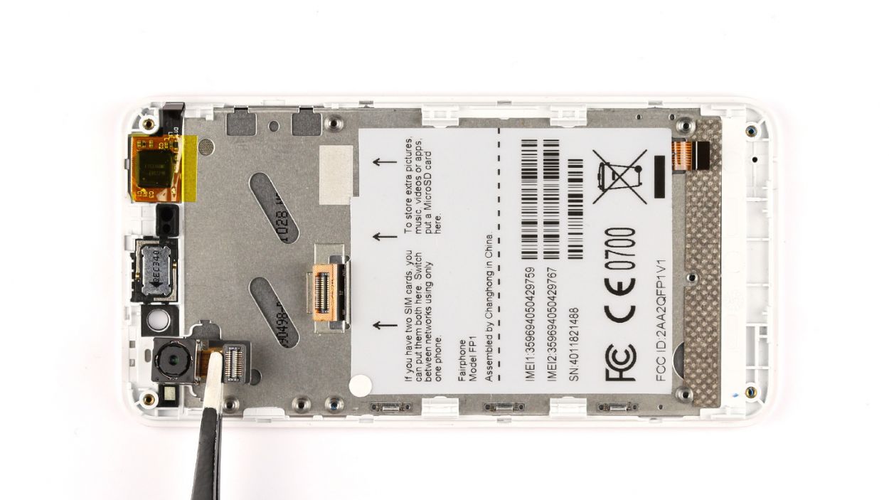
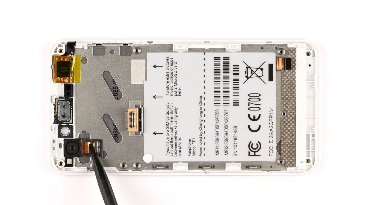
– The rear-facing camera is glued to the display frame. Using the steel spatula, carefully detach the camera.
– Remove the camera.
Step 12

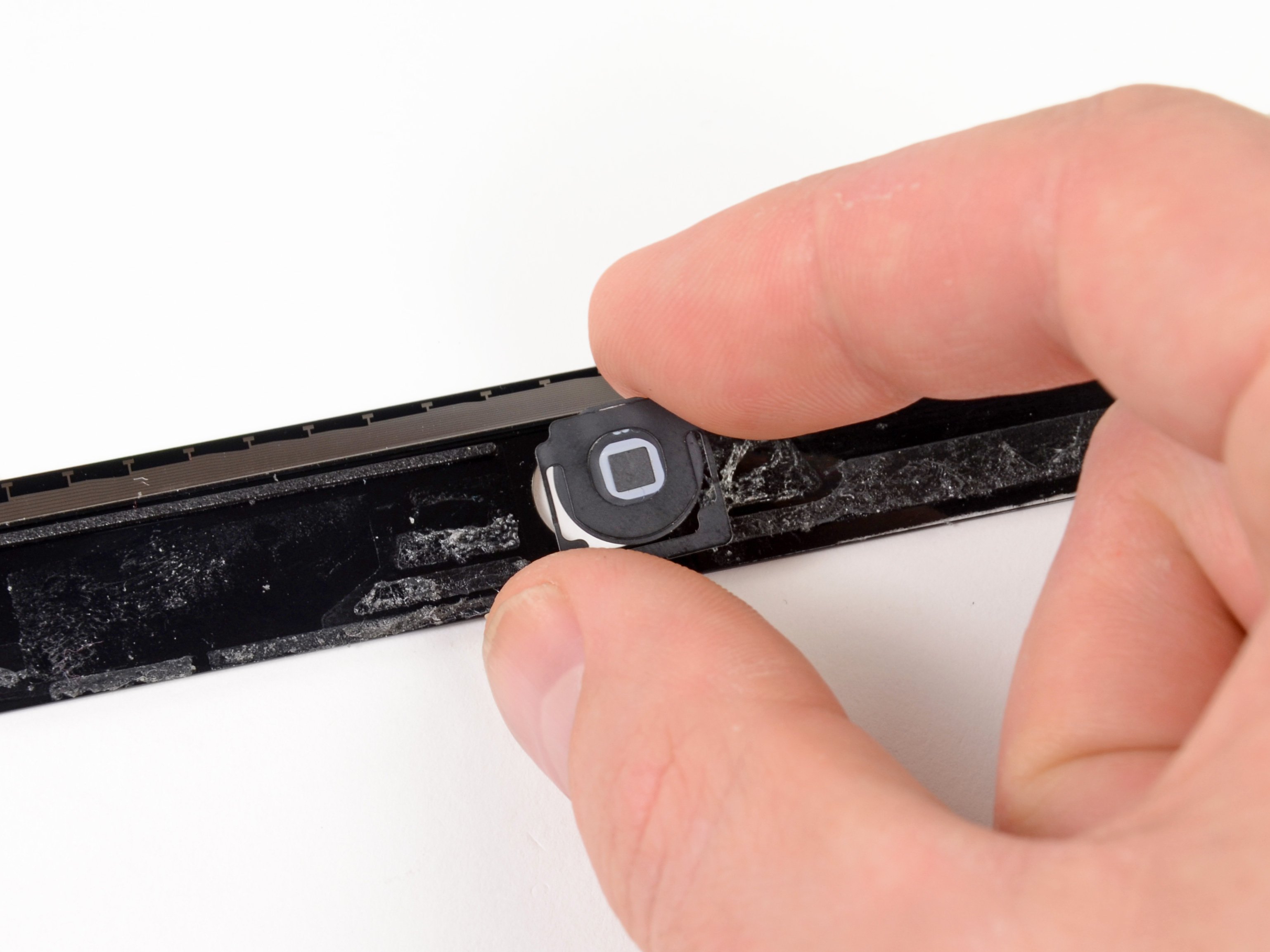
– First up, the earpiece is glued snugly to the display frame. Grab your trusty steel spatula and gently tease the earpiece away.
– Next, lift the earpiece out of its cozy little spot in the display frame.
Step 17


– Let’s start by placing that sub-board right on the display frame like it belongs there.
– Now, grab those two Phillips screws and fasten the sub-board to the display frame—just snug them up, okay? We’re going with 2 x 3.9 mm Phillips screws here.
– Next up, we need to connect the flexible flat cable to the sub-board. Make sure to lock that connector in; we want it secure!
– And don’t forget, it’s time to attach the antenna cable to the sub-board. You got this!
Step 18


– Gently place the logic board at a perfect 90° angle against the display.
– Next, connect the display to the logic board with care.
– Now, position the logic board back into its cozy spot on the display frame.
– Finally, secure it all in place with those three trusty Phillips screws (3 x 2.2 mm Phillips screws).
Step 19


– Attach the flex cable to the logic board – easy peasy!
– Secure the connection. You got this!
– Pop the cover back on. Almost there!
– Connect the antenna cable to the logic board. High five, you’re rocking it!


Step 22

– Fasten the chassis in place using your Phillips screwdriver and five delightful 3.9 mm screws! 😍🎉
– Pop that seal back home! 🏠🖇️
Step 23

– Time to pop those SIM cards and microSD card back in their cozy little homes!

Step 25

– Time to get that back cover back on! Just make sure those two little tabs on the back cover snugly fit into the chassis.
– Give the back cover a gentle press until you hear that satisfying click. You’re almost there!