DIY Guide to Replace Galaxy Note 9 Screen
Duration: 90 min.
Steps: 32 Steps
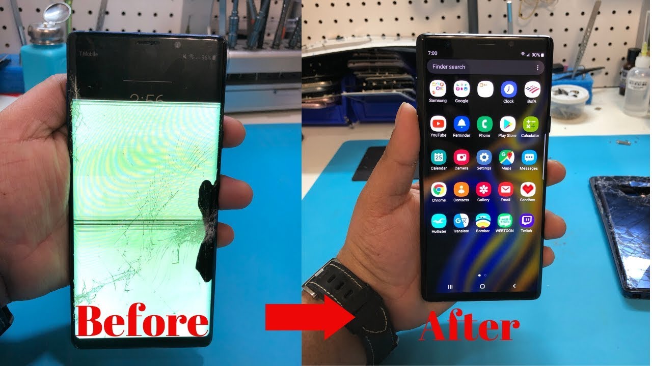
Get ready to tackle your Galaxy Note 9 display replacement with this fun, step-by-step guide! We’re not just swapping out that cracked screen; we’re replacing the whole display unit, frame and all, for a fresh start. Just a heads up, if your new part needs a few bits from the old display, you’ll be taking those over too! Opening the Galaxy Note 9 can be a bit tricky since we have to pop off the glass back cover. So, grab a snack, settle in, and give yourself plenty of time for this one. Don’t forget to back up your data before diving in, and make sure you have a tidy workspace ready to go. If you hit a snag, feel free to reach out via our live chat or drop a comment on the step you’re stuck on. Happy repairing!
Step 1
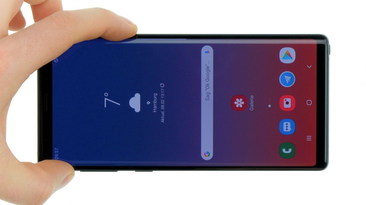
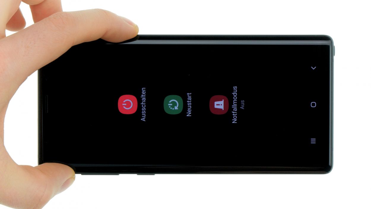
– First things first, let’s give your device a little nap! Press and hold that power button until you see the ‘Power off’ option pop up.
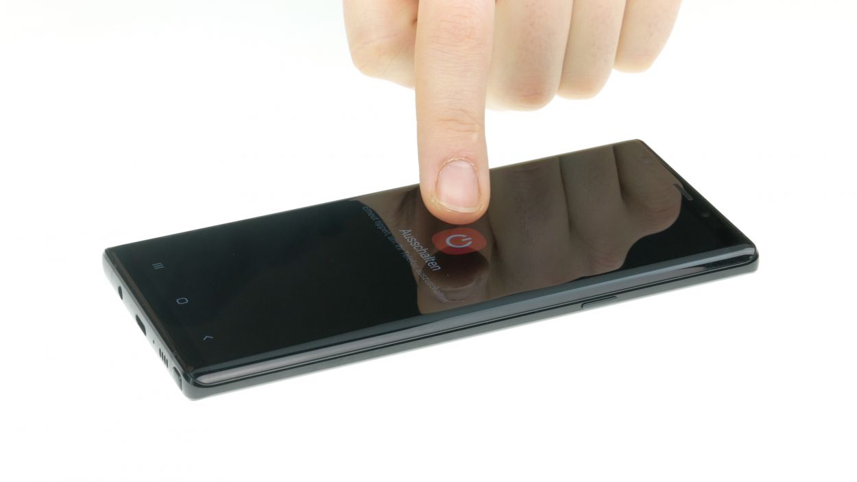
– Now, tap that option with your finger to let your Galaxy Note 9 know it’s time to rest. Hang tight until the screen goes dark!
Step 2
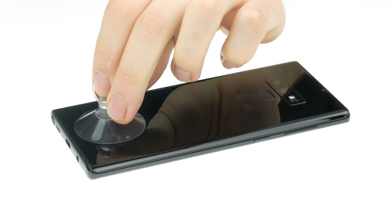
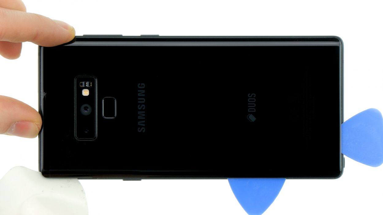
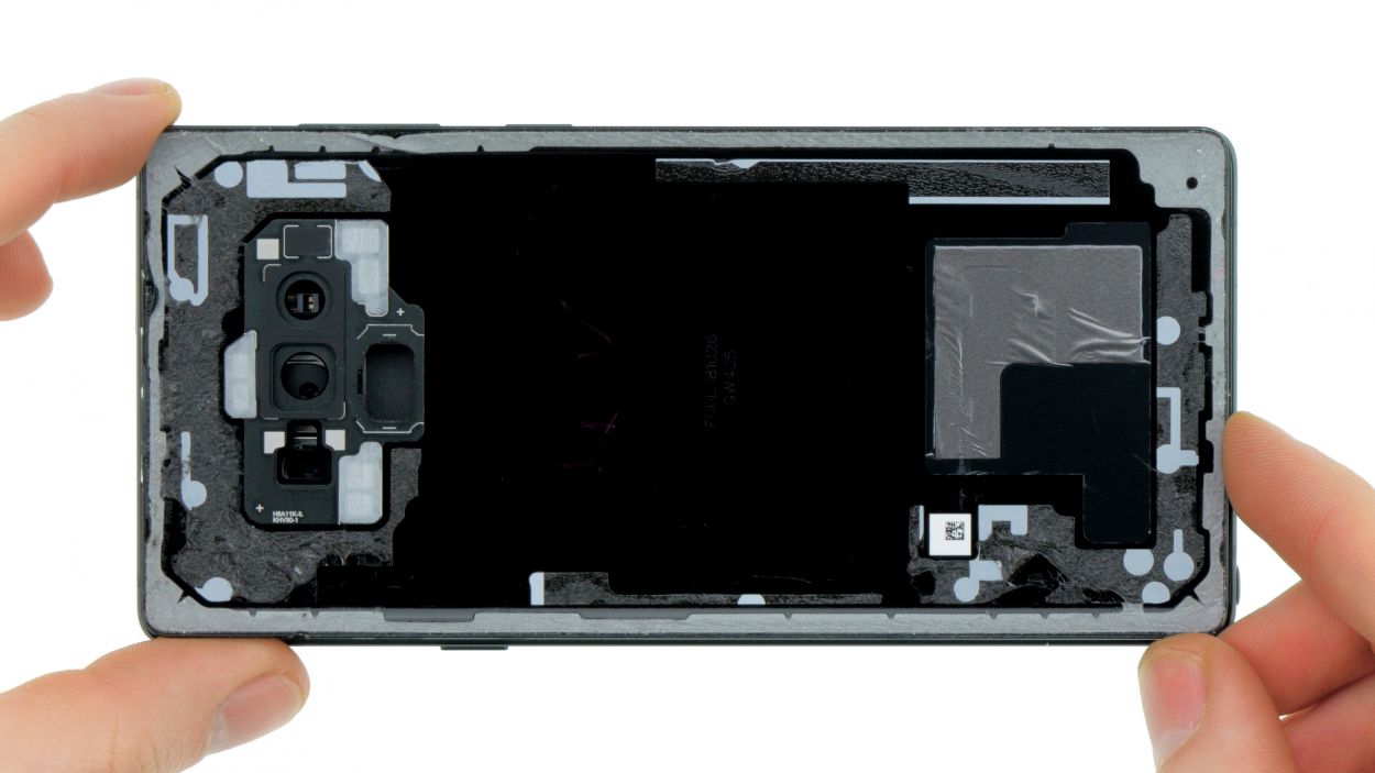
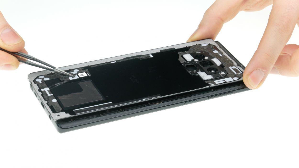
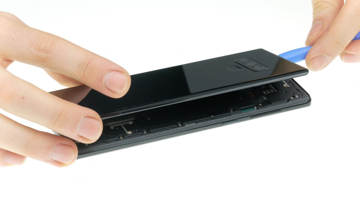
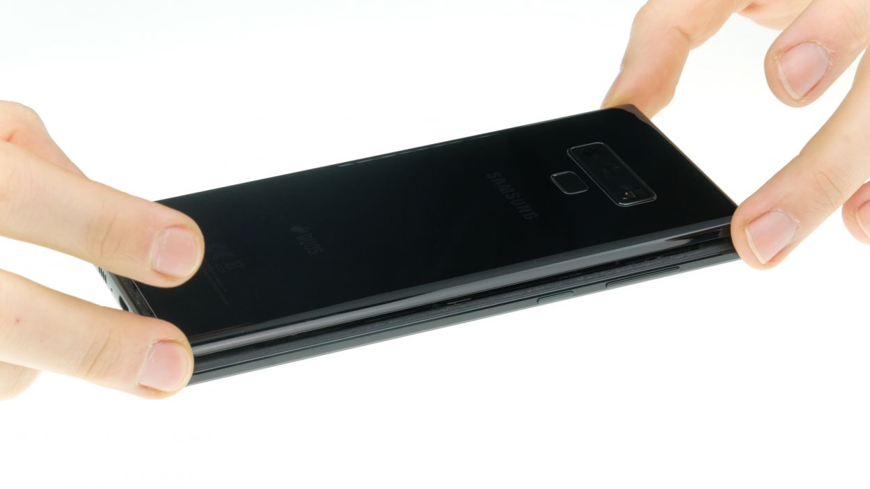
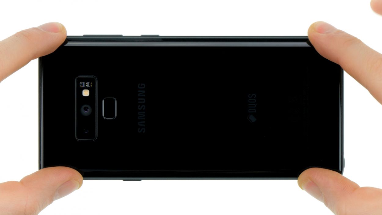
– The back cover is really stuck to the chassis, but don’t worry! Just warm up your device evenly with some hot air to loosen that glue. A cozy temperature of 60 – 80°C should do the trick. Remember, it should still be comfortable to touch!
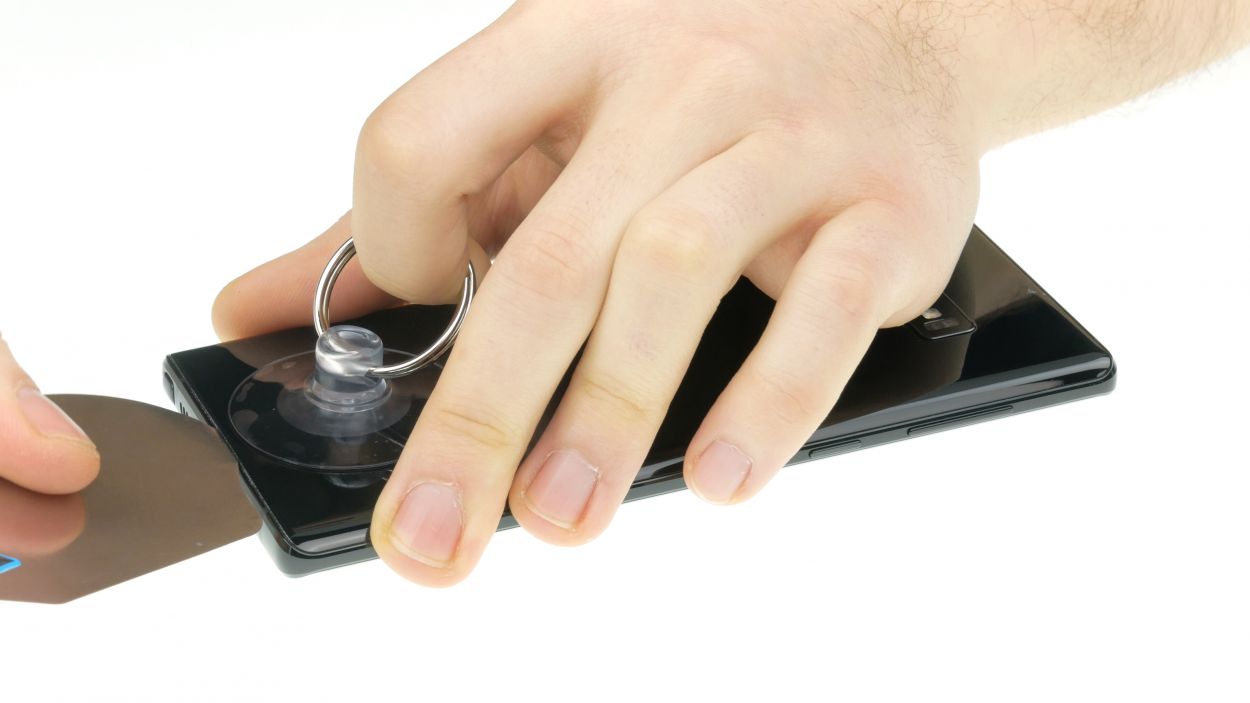
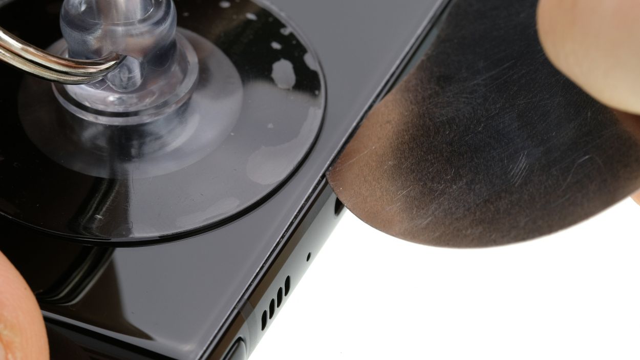
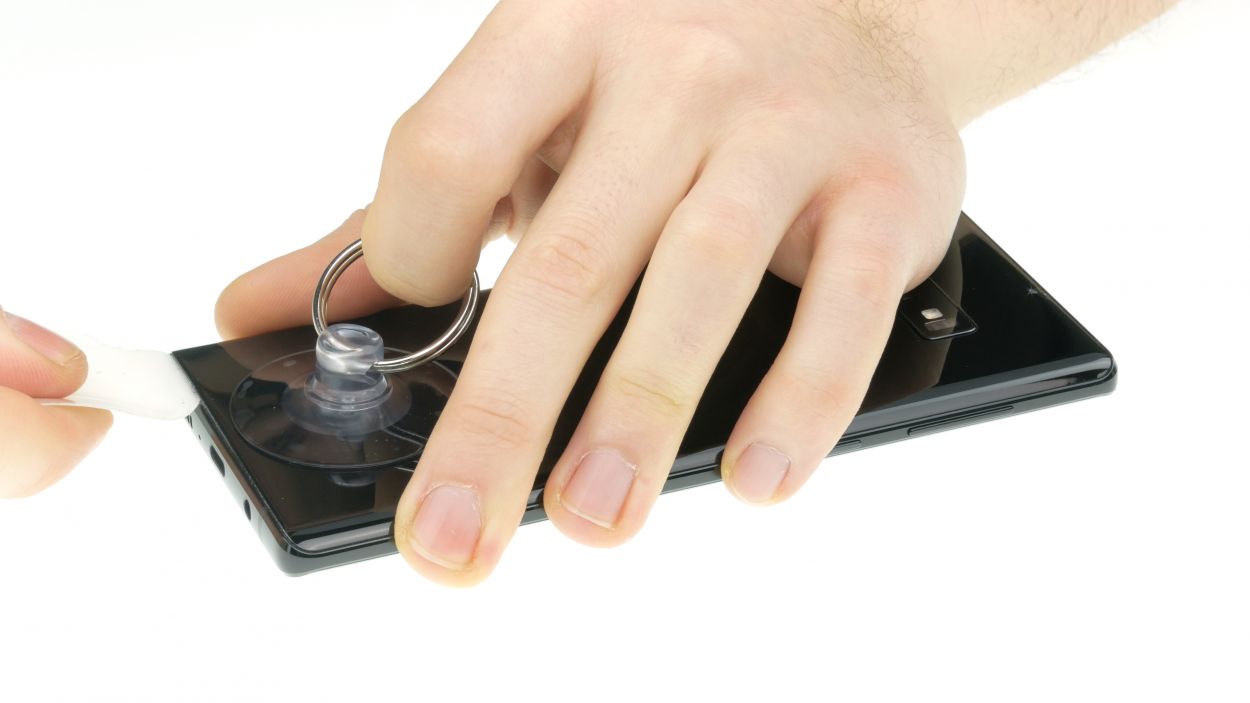
– To easily pop off the back cover, grab a flat and flexible tool like the iPlastix or iFlex. You’ll also want a few picks handy to gently pry it free all around. You’ve got this!
Hey there! Just a friendly reminder to handle that back cover with care—it’s a bit fragile! If it’s giving you a hard time, feel free to warm it up a few times and give it another go. Remember, taking your time is key; it might take around half an hour, but being patient will help you avoid any mishaps. You’ve got this!
The iPlastix is crafted from plastic, so it won’t leave a scratch on your device – no worries there! Just a heads up, though, it’s a bit on the soft side and can be a little finicky when you’re trying to get it in. But hey, you’ve got this! If you need help, you can always schedule a repair.
Tools Used
- heat gun to heat parts that are glued on so they’re easier to remove.
In most cases, you can also use a hairdryer.” rel=”noopener”>Heat gun - screen and the frame. The practical iFlex is made of stainless steel and sits comfortably in the hand. This makes it the perfect assistant for every smartphone repair.” rel=”noopener”>iFlex Opening Tool
- iPlastix Opening Tool
- VAKUPLASTIC Suction Cup
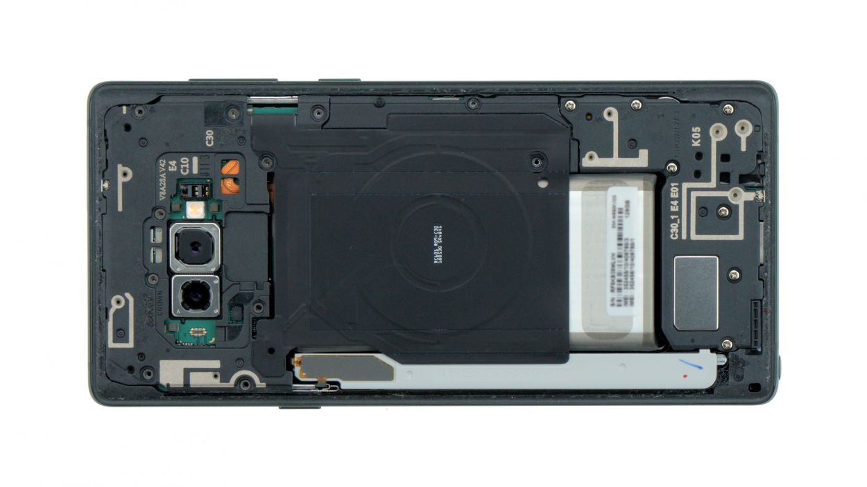
Step 3
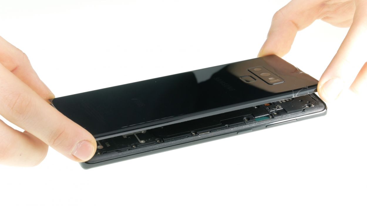
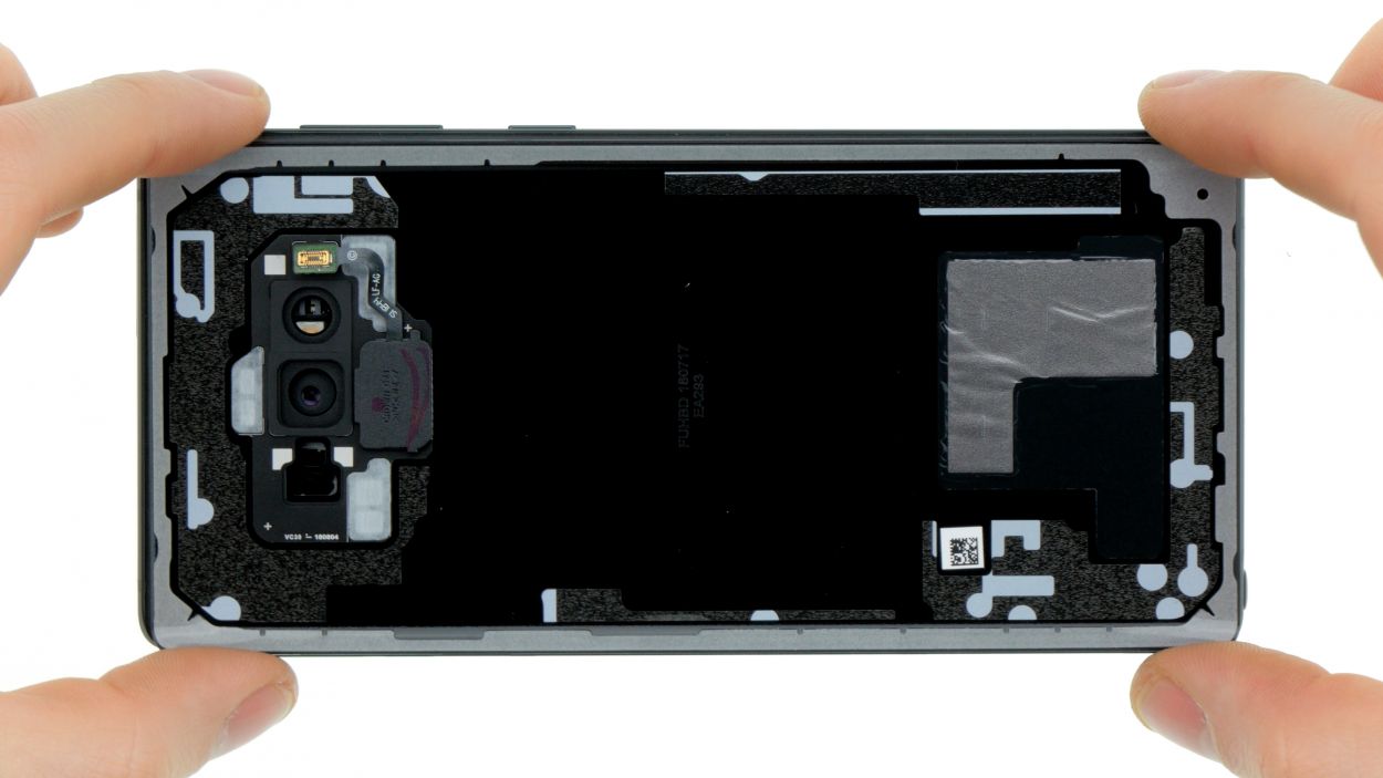
– Once you’ve popped off the back cover, gently lift it up and use that trusty spudger to disconnect the fingerprint sensor.
– Now, go ahead and fully remove the back cover and place it somewhere safe for later!
Tools Used
Step 4
11 × 4,0 mm Phillips
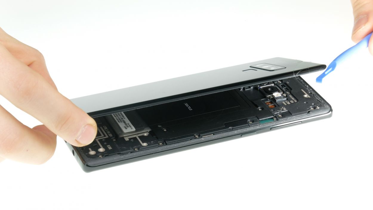
– First things first, let’s tackle those screws holding the upper cover to the display. Time to get them out!
– Next up, the cover is snugly latched onto the case, and the lower part of the antenna has a bit of glue keeping it in place. Grab a flat tool and gently slide it under the latches to free them.
– And now, let’s say goodbye to the antenna. You’ve got this!
Step 5
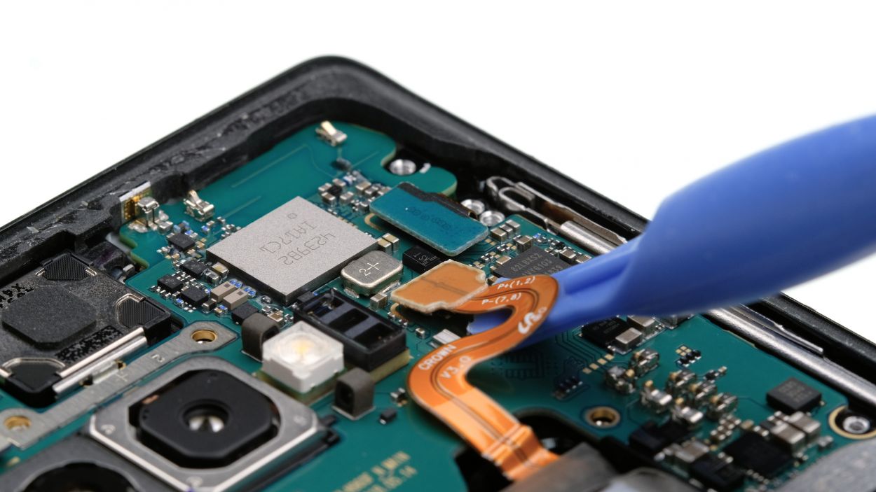
Battery connector
When you’re prying things open, make sure to start from a side without those tiny components on the motherboard. This way, you can keep those delicate capacitors and ICs safe and sound!
– Grab your trusty spudger and gently disconnect the battery contact from the motherboard. You’ve got this!
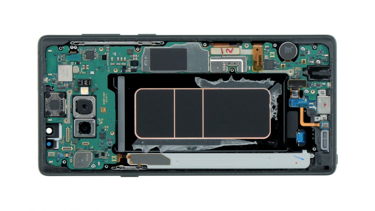
Step 6
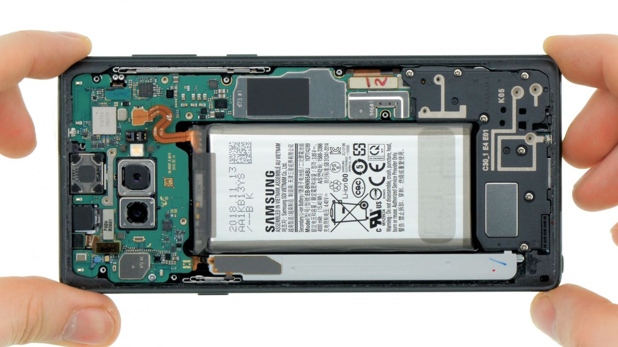
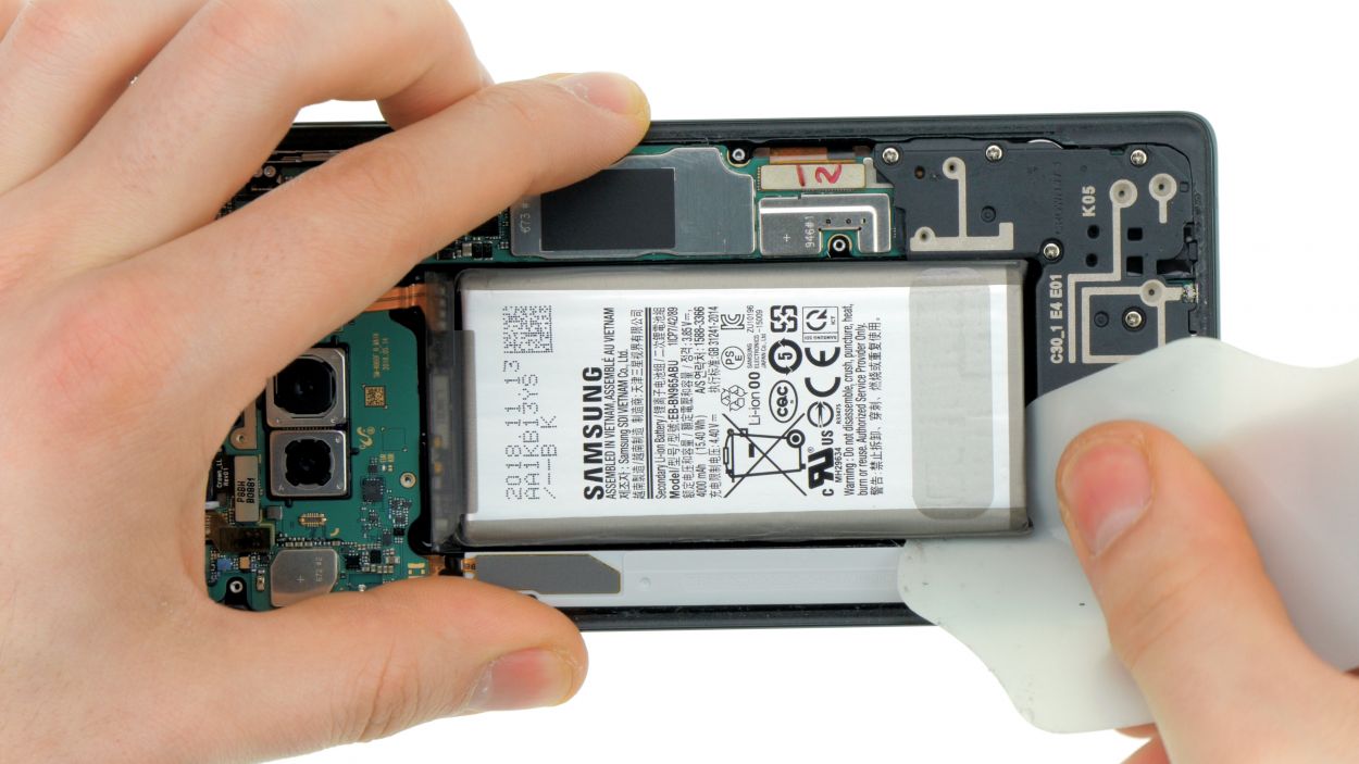

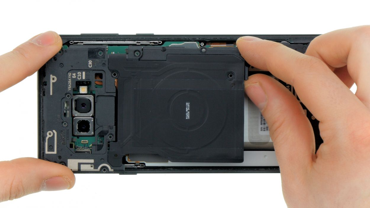
Avoid giving your battery a sauna session or trying to twist it into a pretzel. Keep it cool and straight!
Check out the video (just hit that play button in the upper right corner of the first image) to watch how to release the battery like a pro!
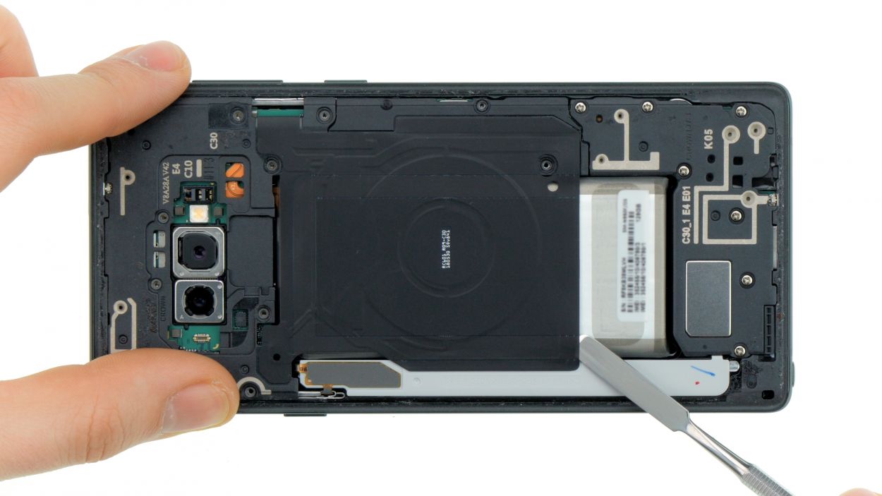
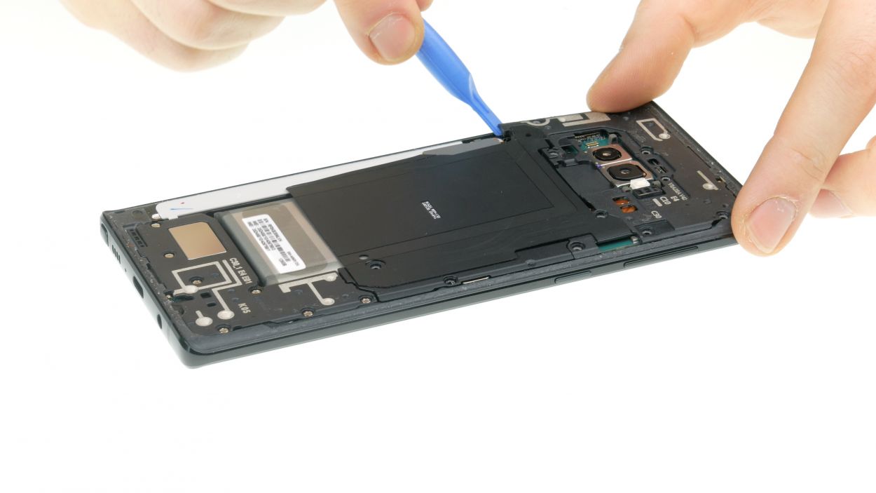
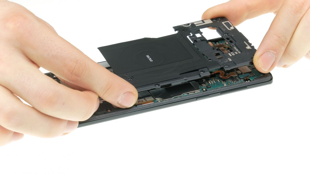
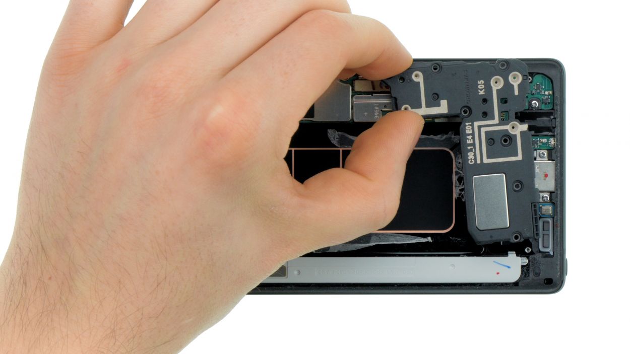
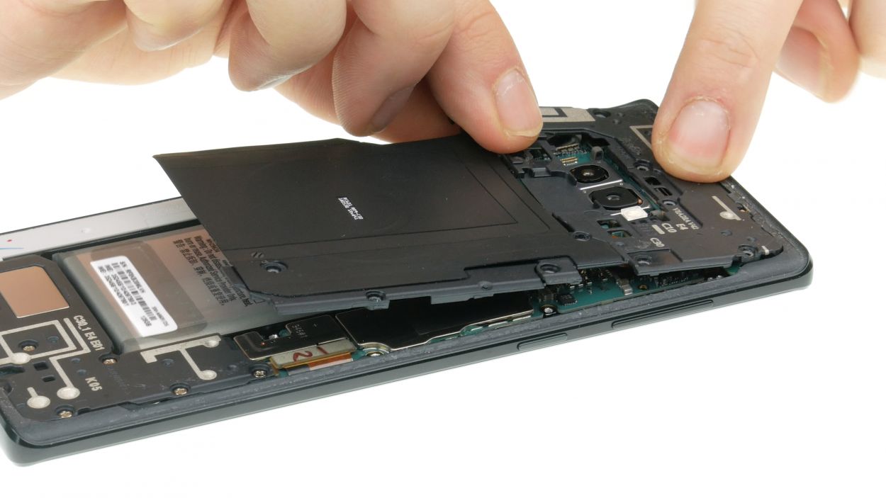
– Let’s get the heat rolling! Direct your hot air on the display side to soften that adhesive up.
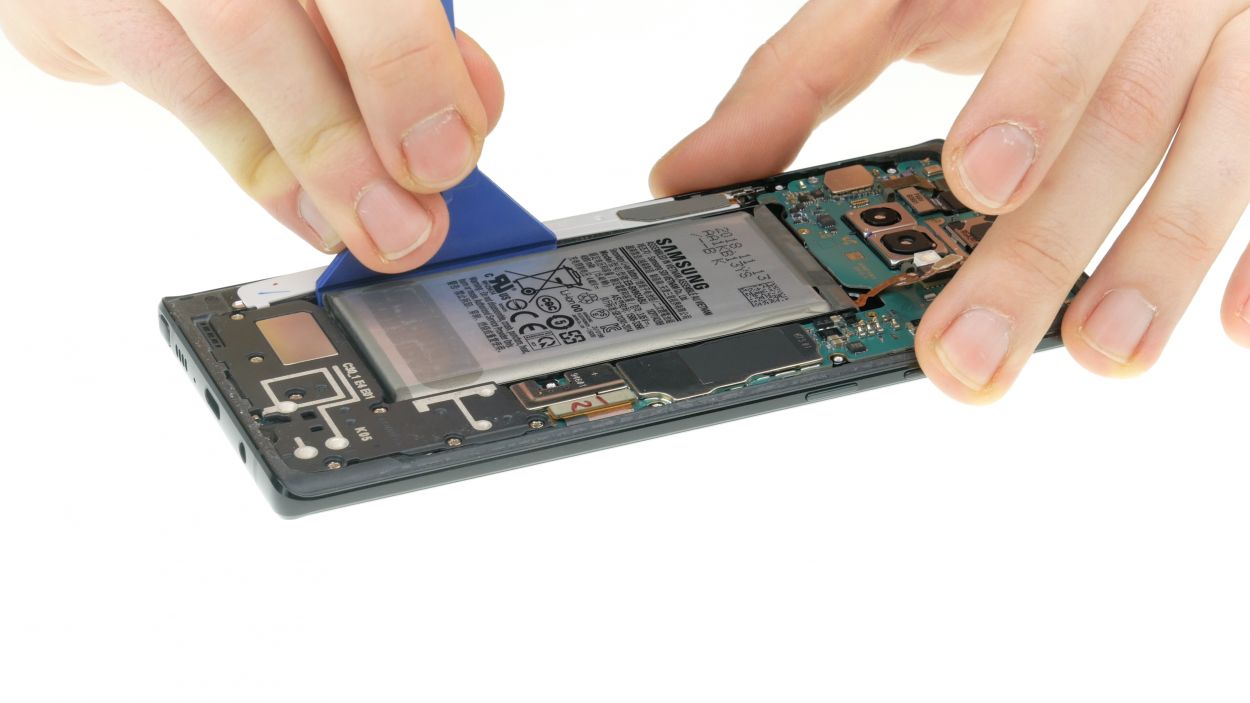
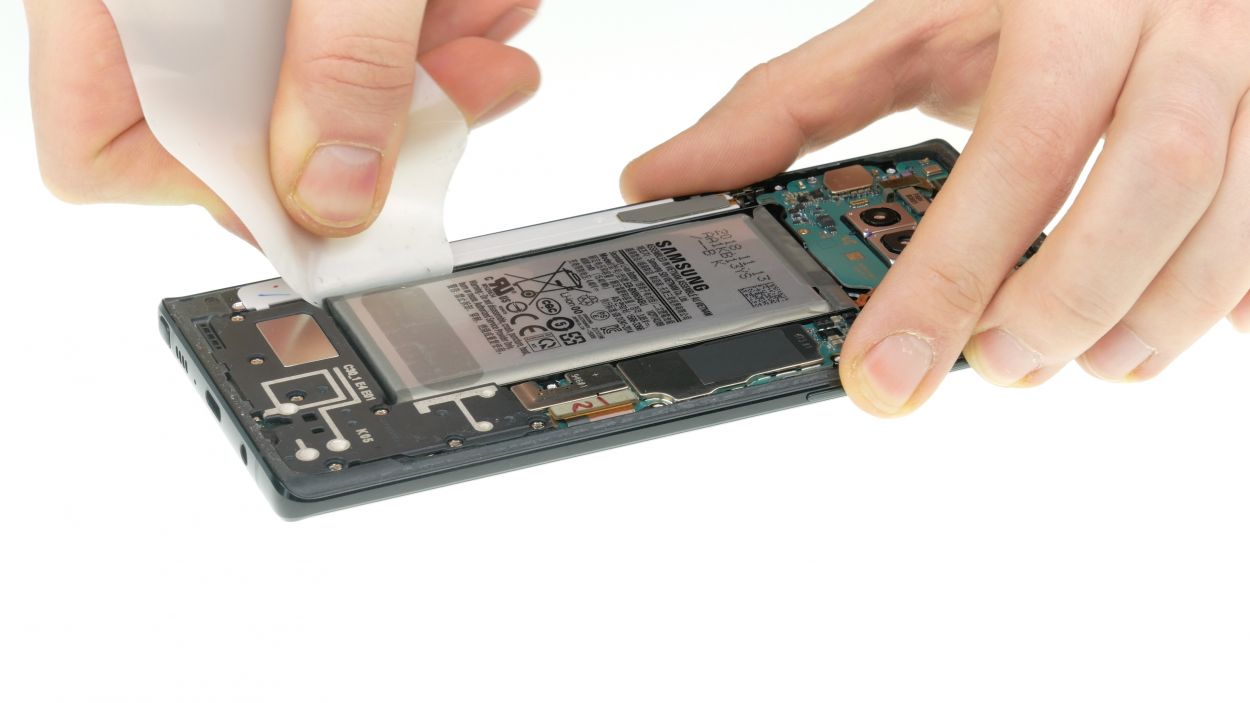
– Grab your flat tool, like the iFlex, and gently glide it around the battery to loosen things up.
– If the iPlastix isn’t quite cutting it, feel free to bring out the wide battery spudger for some extra muscle.
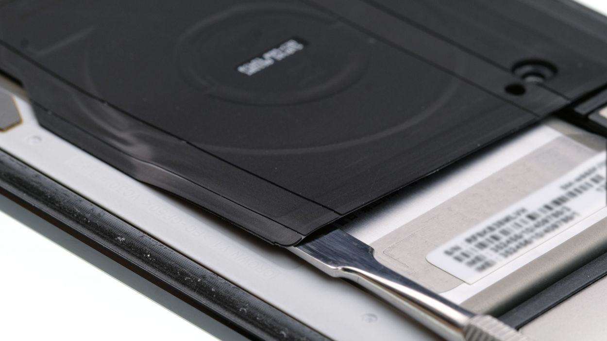
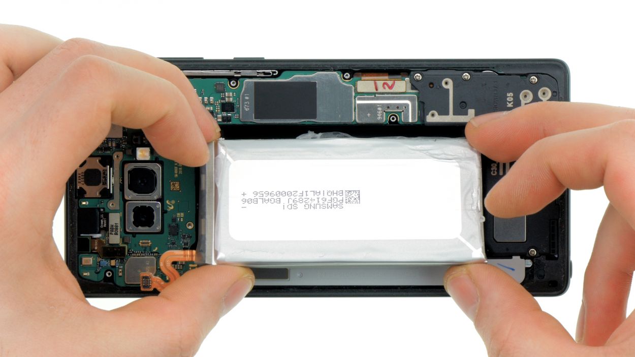
– Carefully slide a flat tool underneath the battery—just a gentle touch to gradually release the adhesive. Remember, don’t poke too deep; we wouldn’t want to accidentally tickle the display from below!
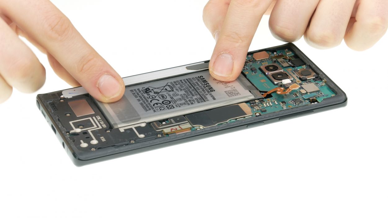
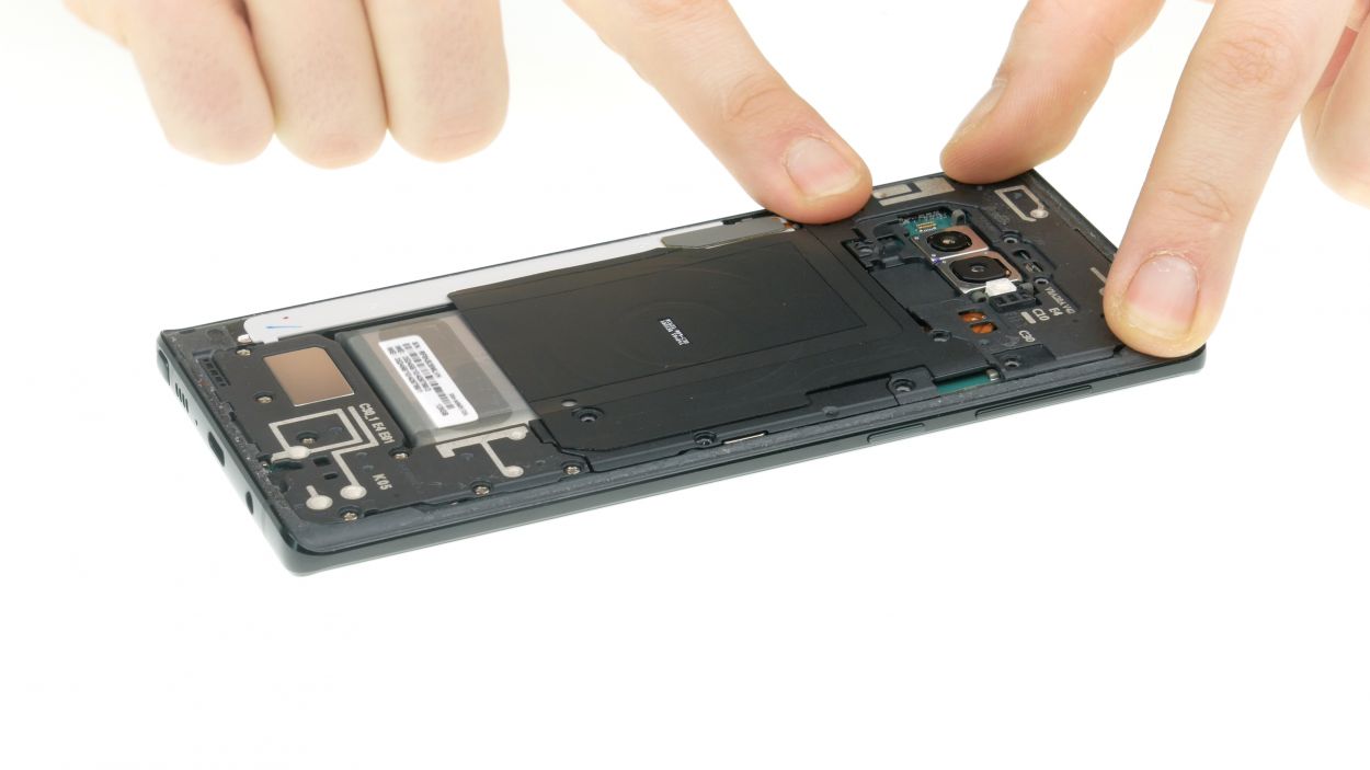
– Once you’ve loosened it up, lift that battery out and set it free from your device!
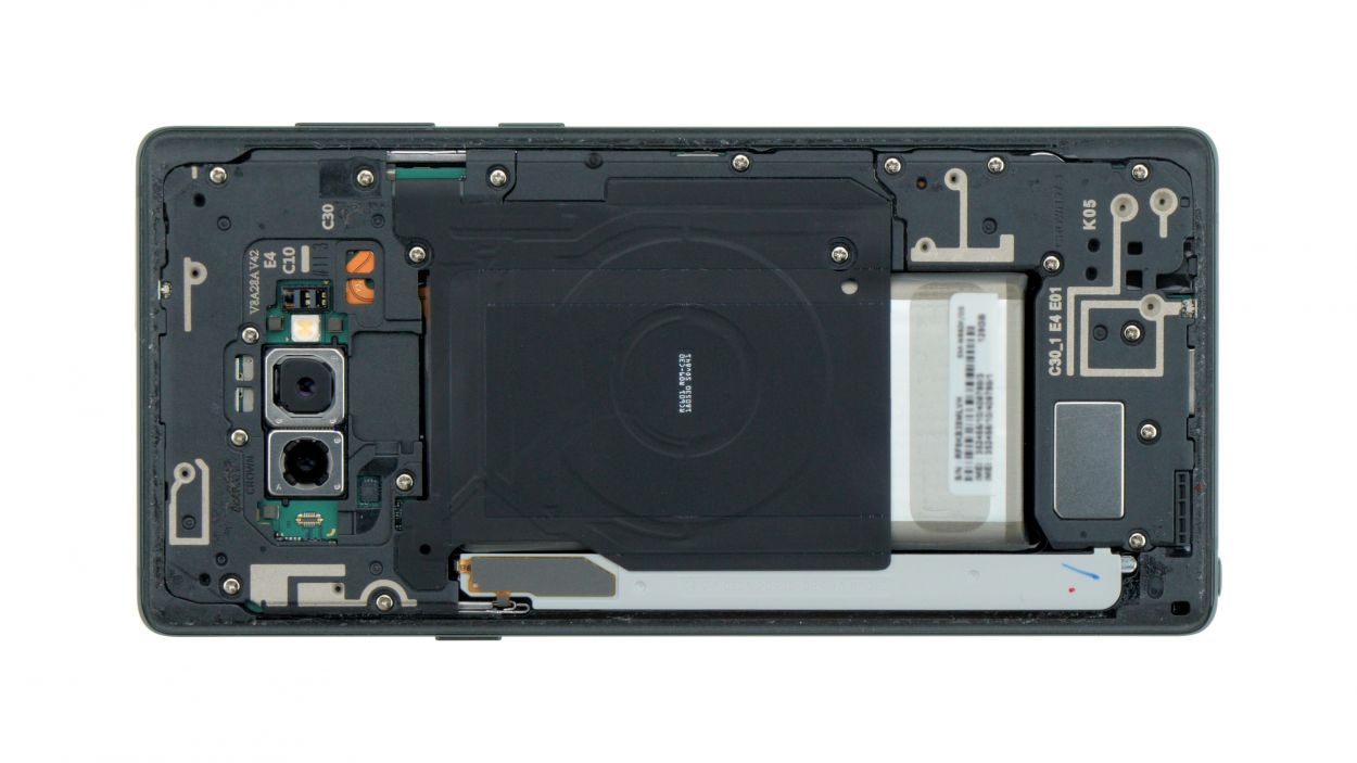
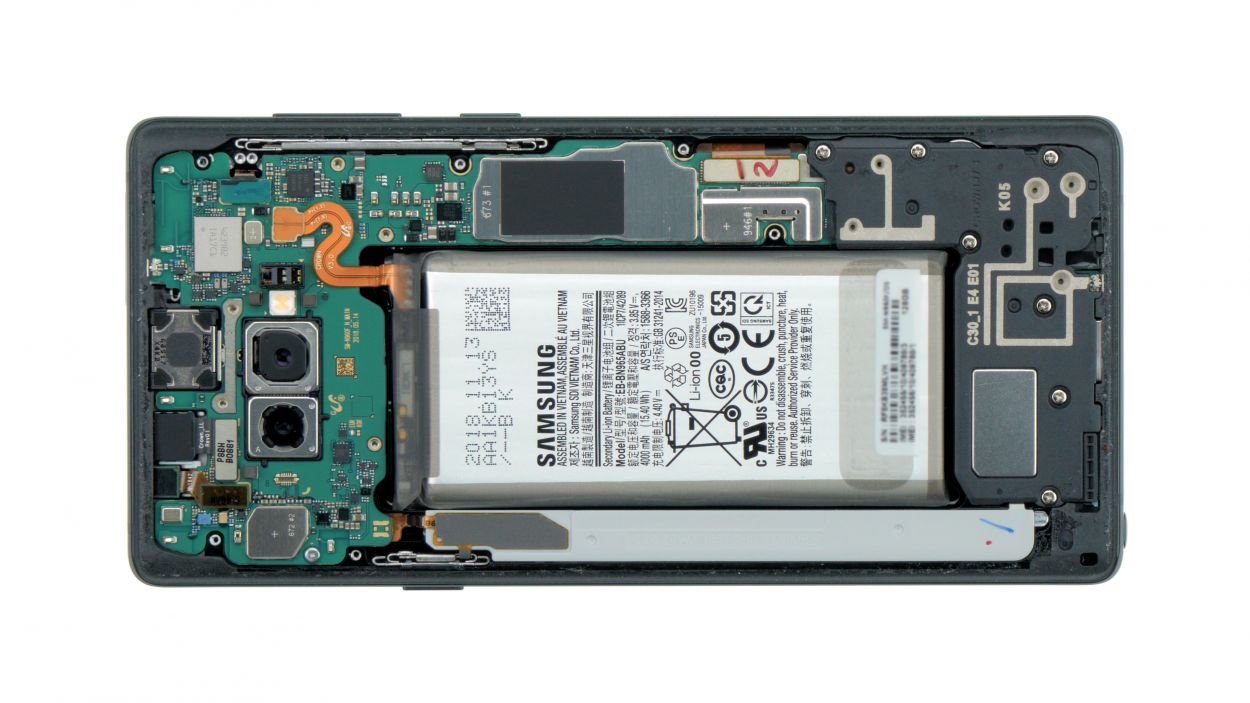
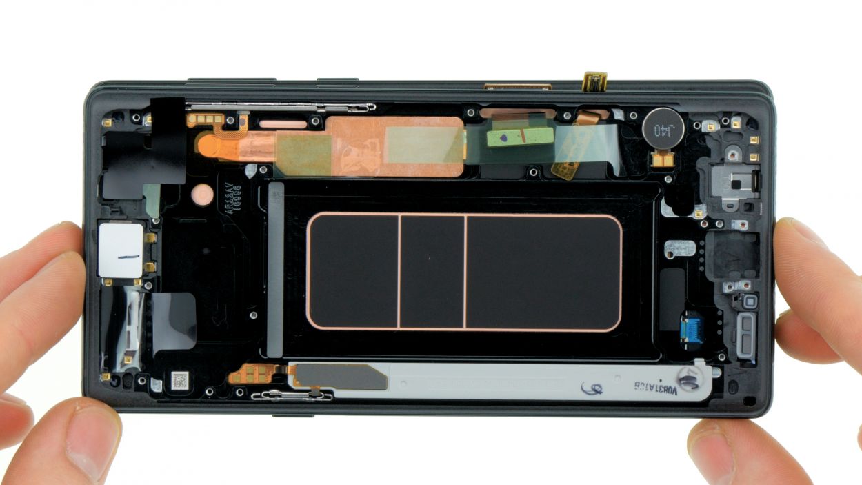
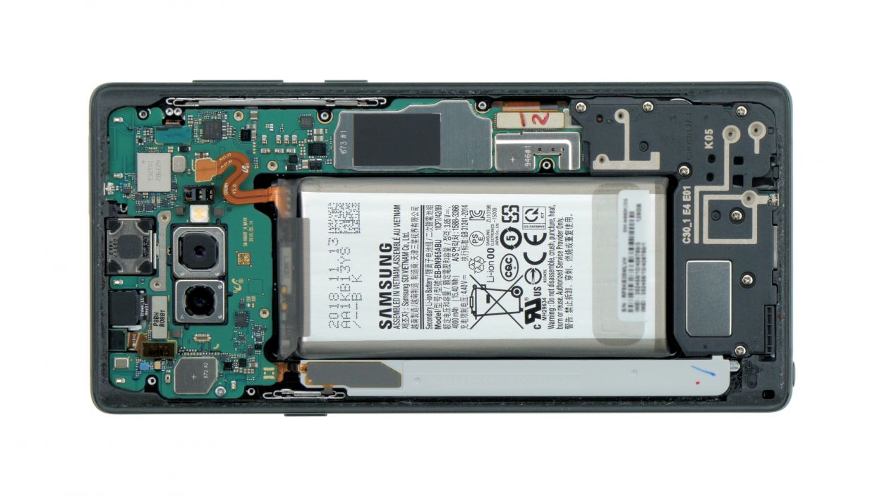
Step 7
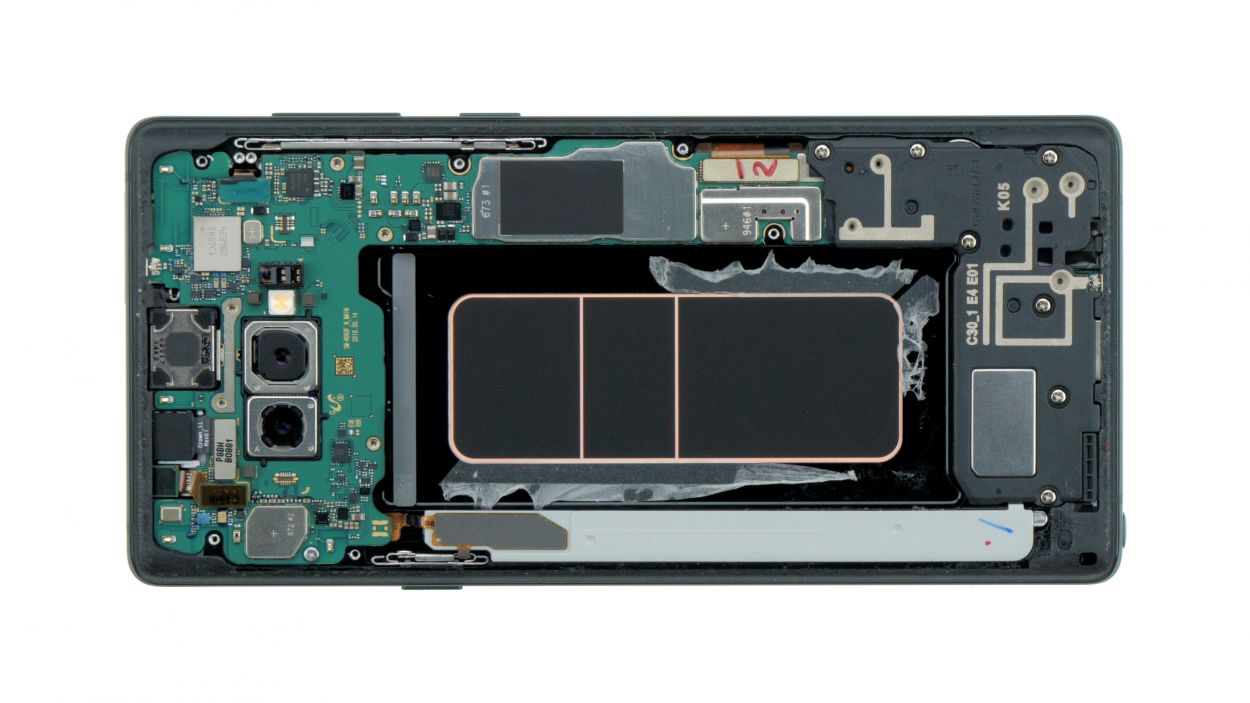
7 × 4,0 mm Phillips
All the screws are the same length, so there’s no need to worry about mixing them up. Keep it simple and organized!
– Unscrew the little bolts holding the speaker to the display, and then gently take it out. Don’t worry, all the screws are the same length, so you won’t mix them up!
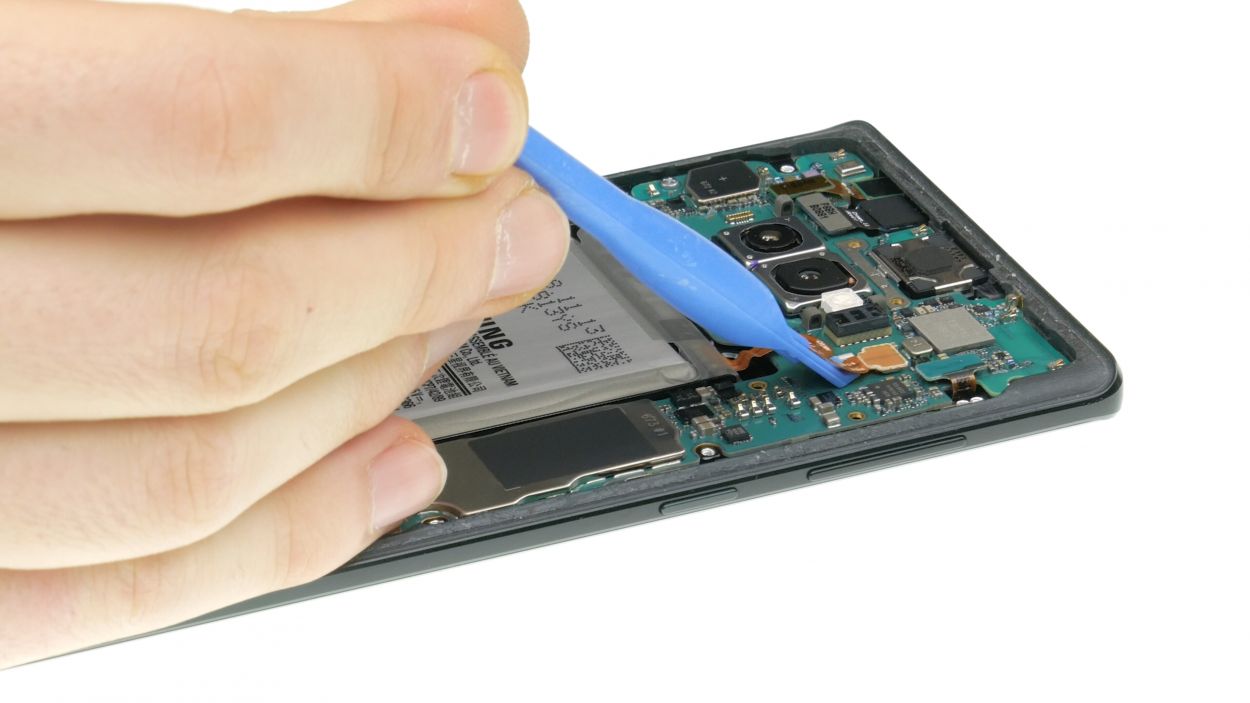
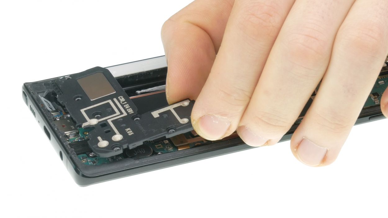
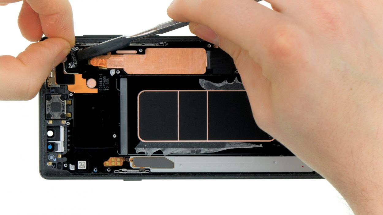
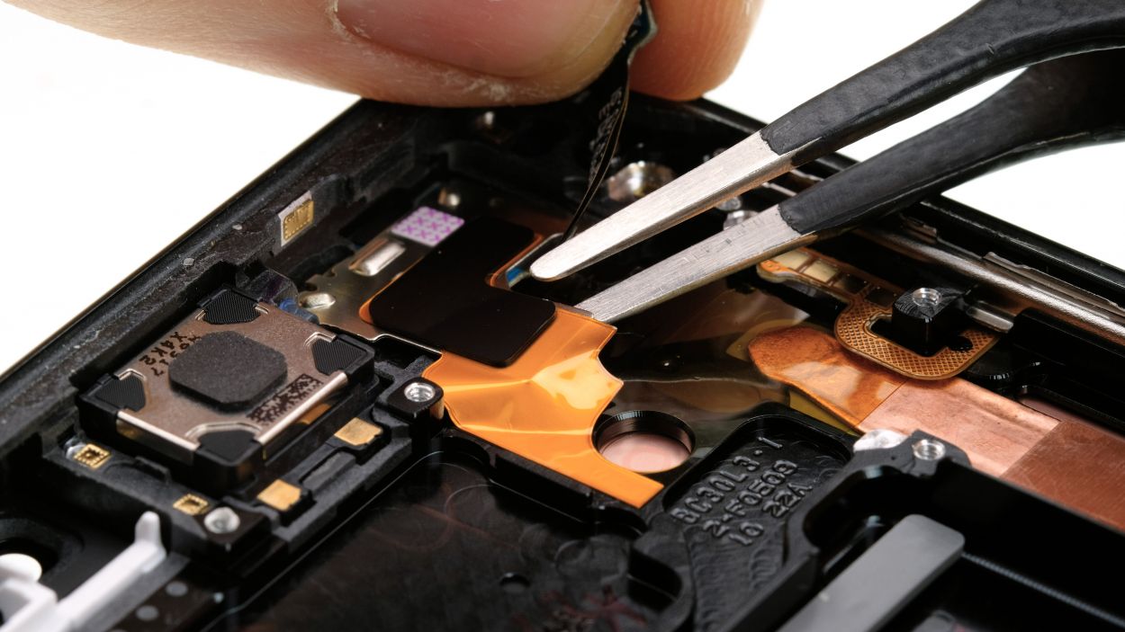
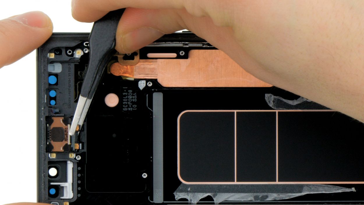
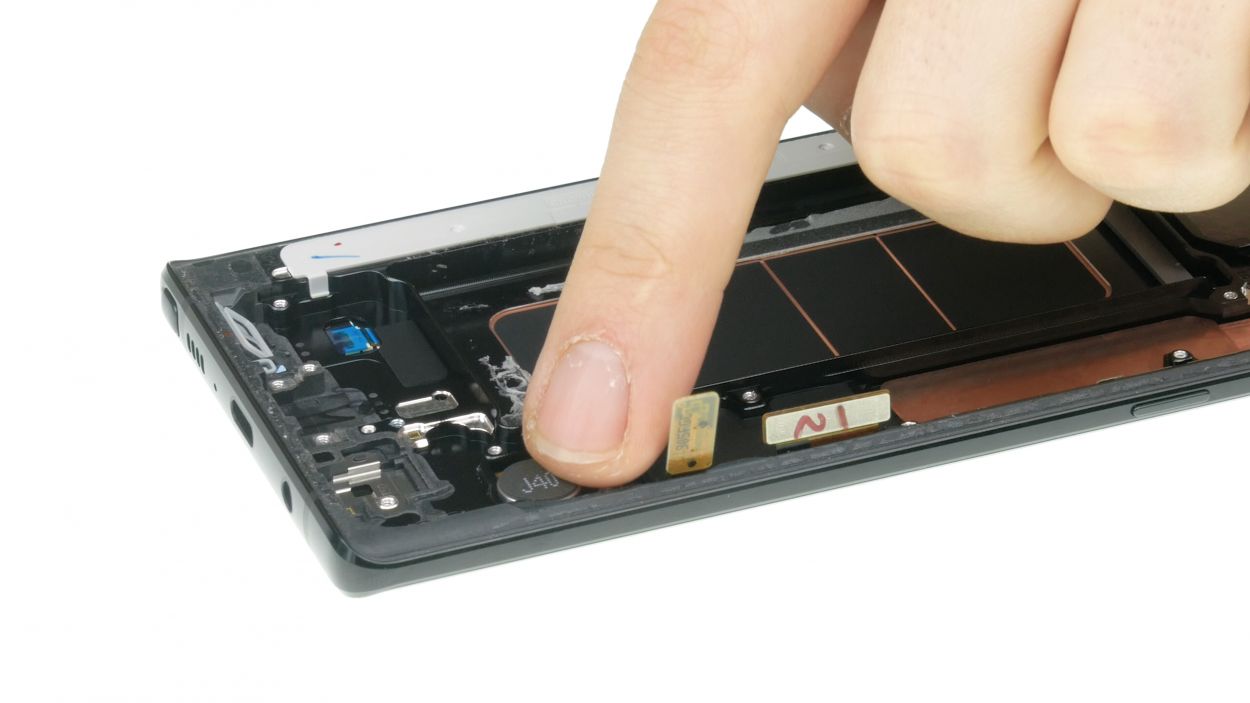
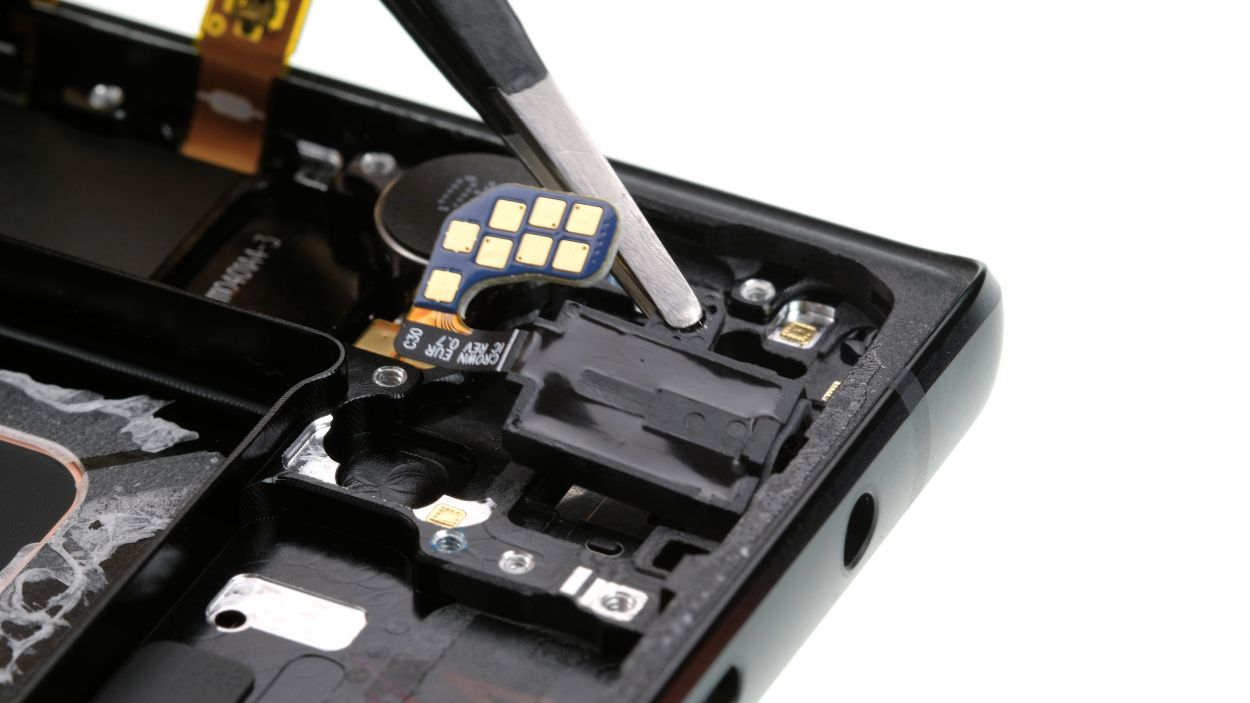
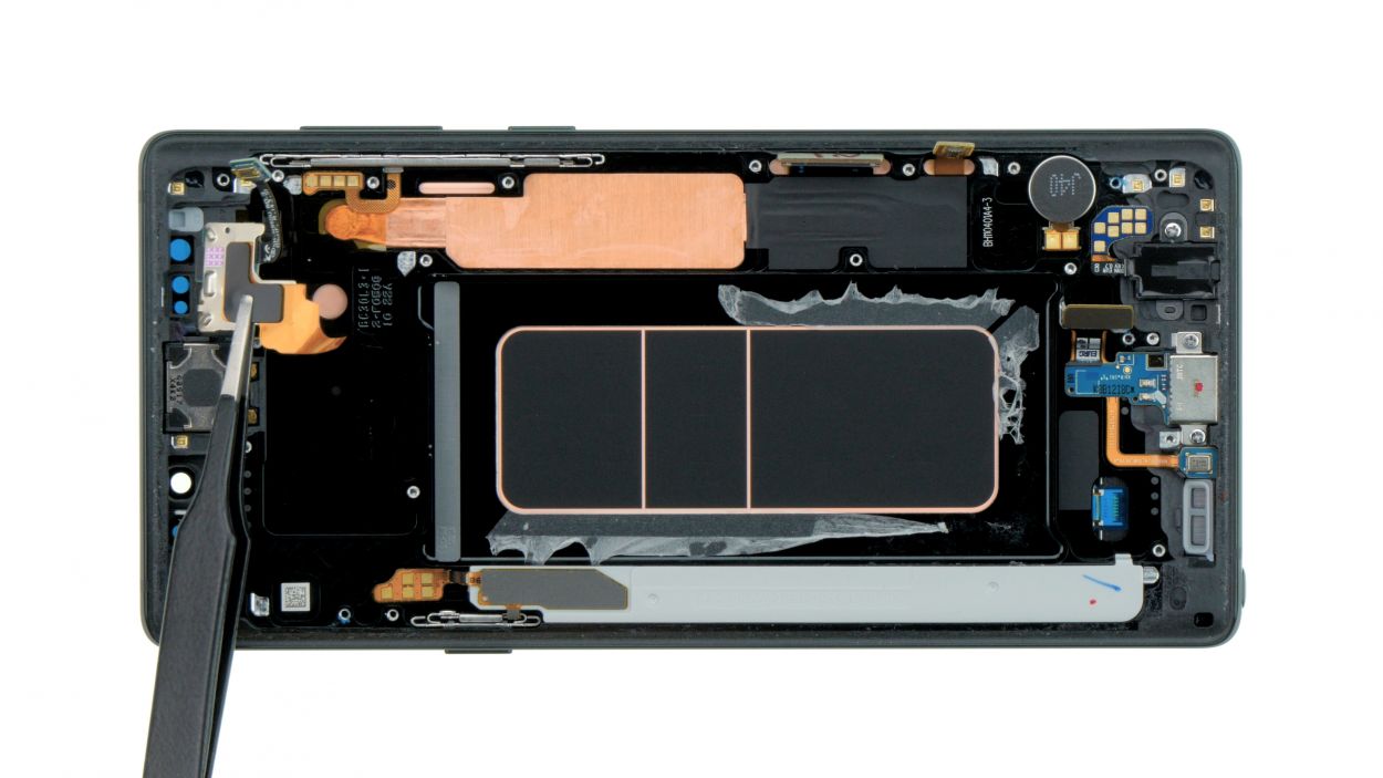
Step 8


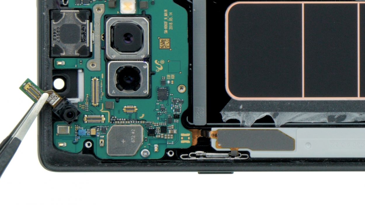
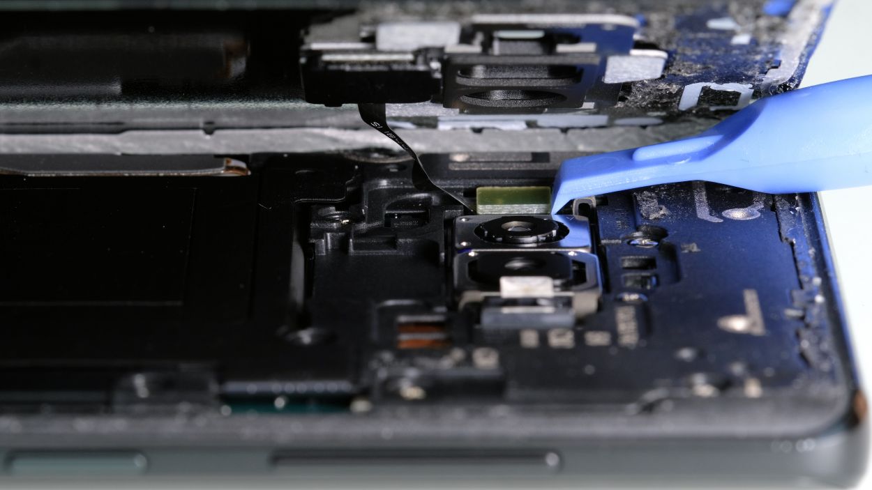
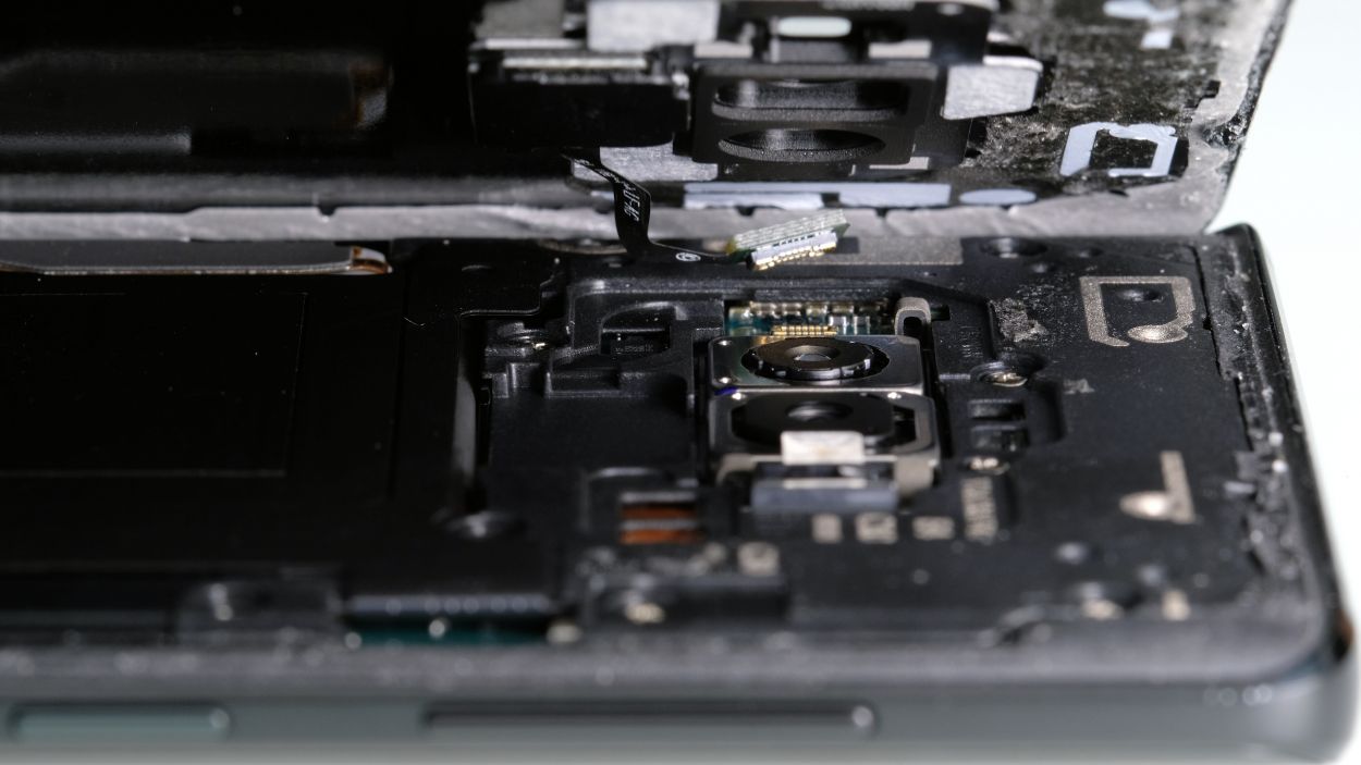
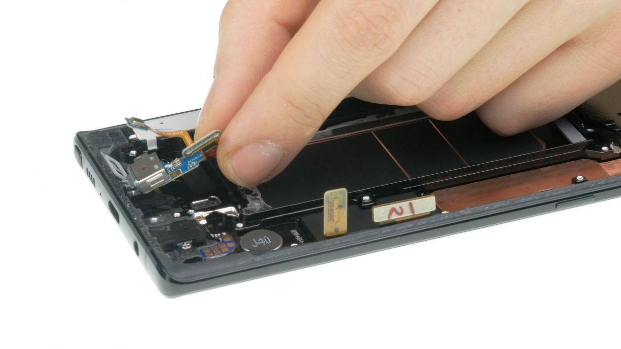
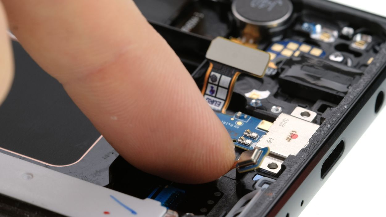
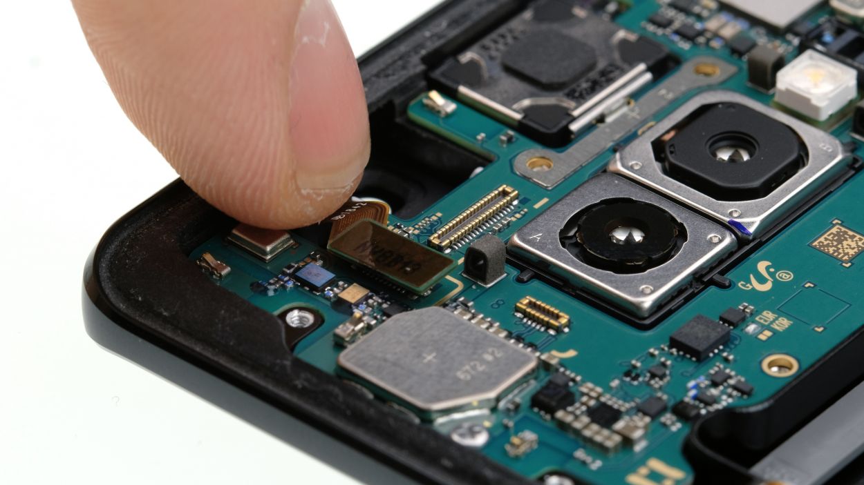
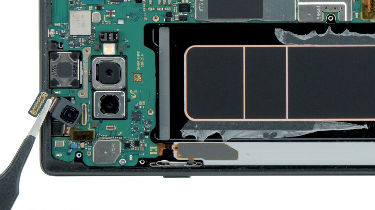
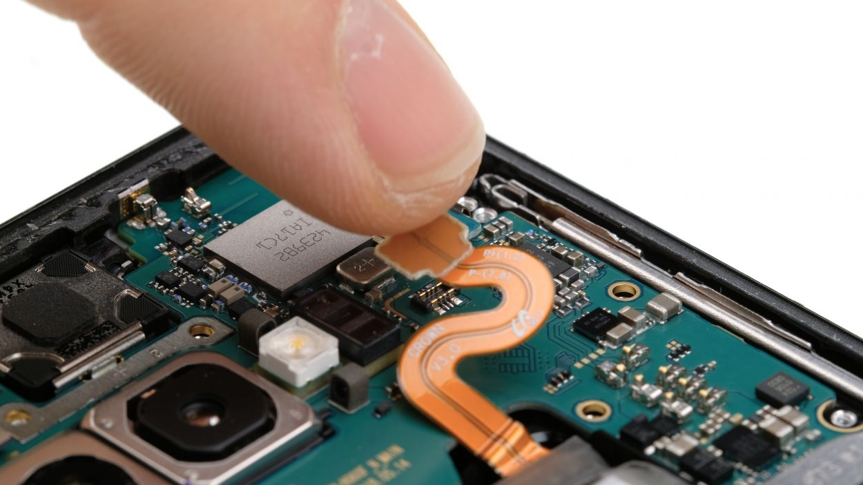
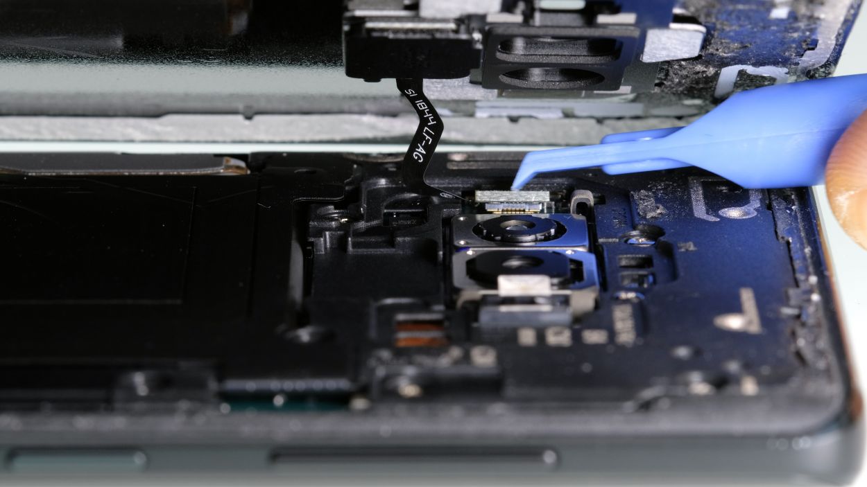
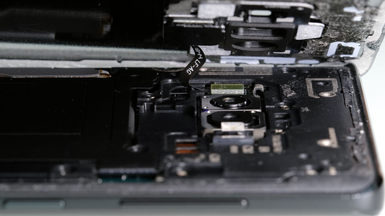
Camera connector
Sensor connector
Just a friendly reminder to be gentle with those tiny components on the motherboard! Always pry from the free side of the connector to keep everything safe and sound.
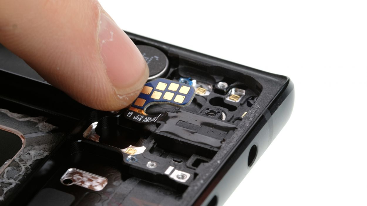
– First up, gently disconnect the connectors for the front camera and the sensor. No need to rush, take your time!
– Once that’s done, you can carefully pry the front camera and sensor out of the chassis. Give them a little wiggle and they’ll come right out!
Step 9

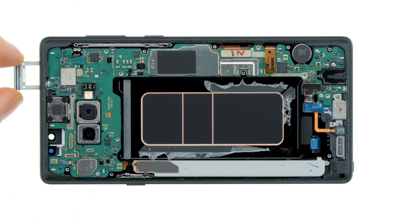
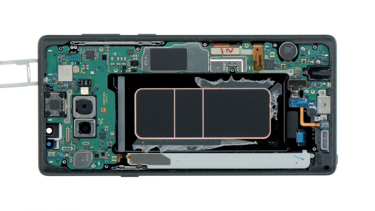
– Grab your trusty SIM tool and gently pop out that SIM card tray from your device. Once it’s free, use your fingers to carefully pull the tray out. Easy peasy!
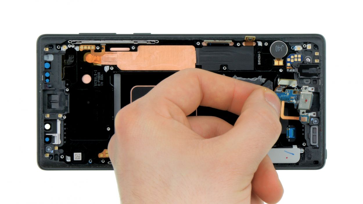
Step 10
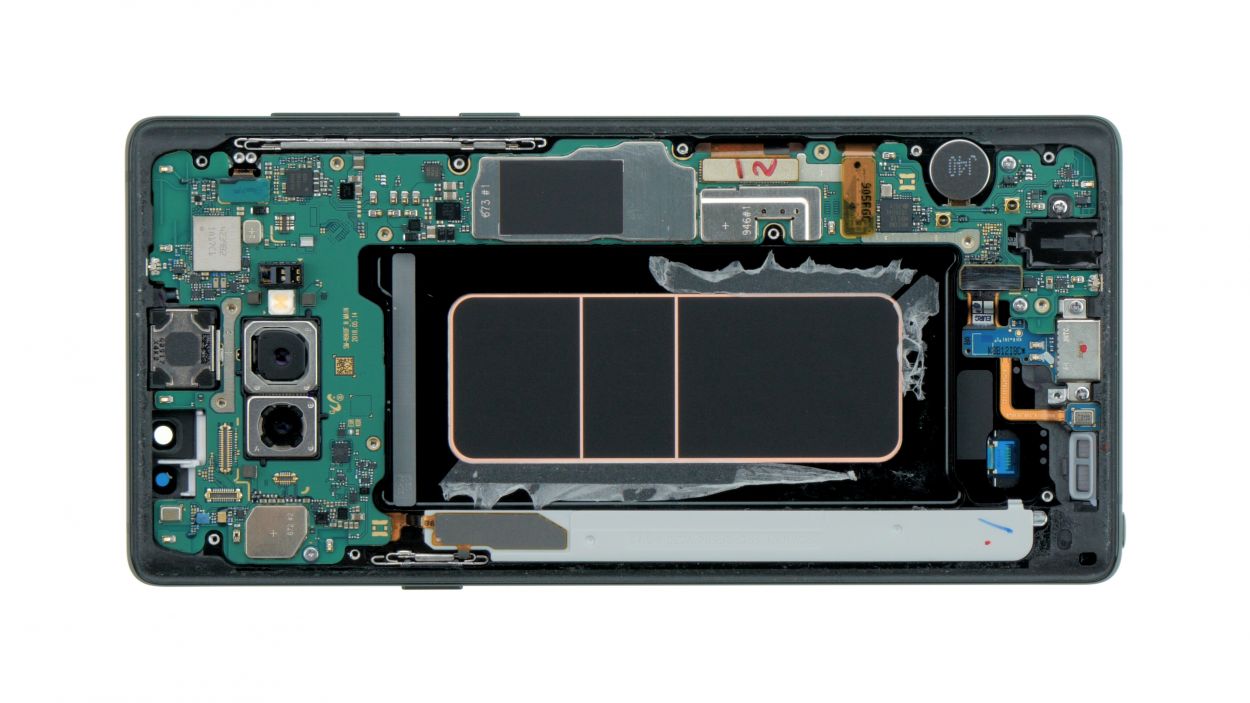
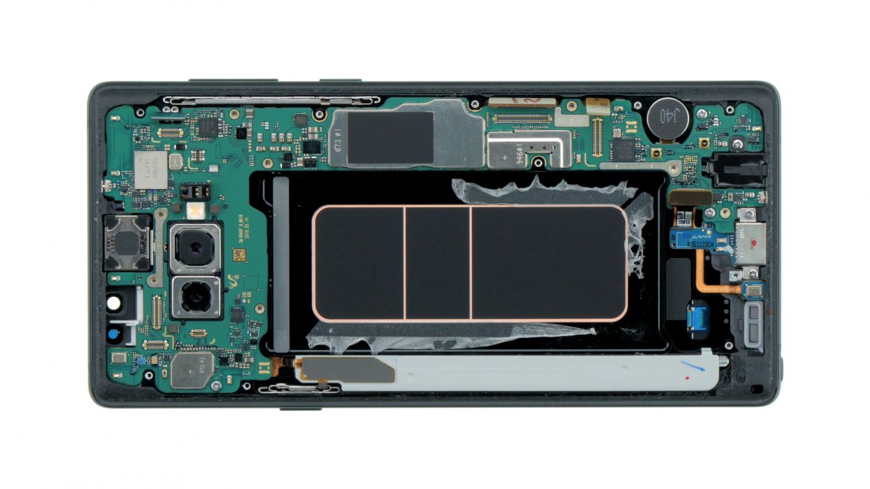
Display connector
USB connector
Button connector
3 × 3,3 mm Phillips
Hey there! Just a heads up: there’s a tiny plastic pin hanging out in the SIM tray opening. Keep an eye on it so it doesn’t take a little tumble!
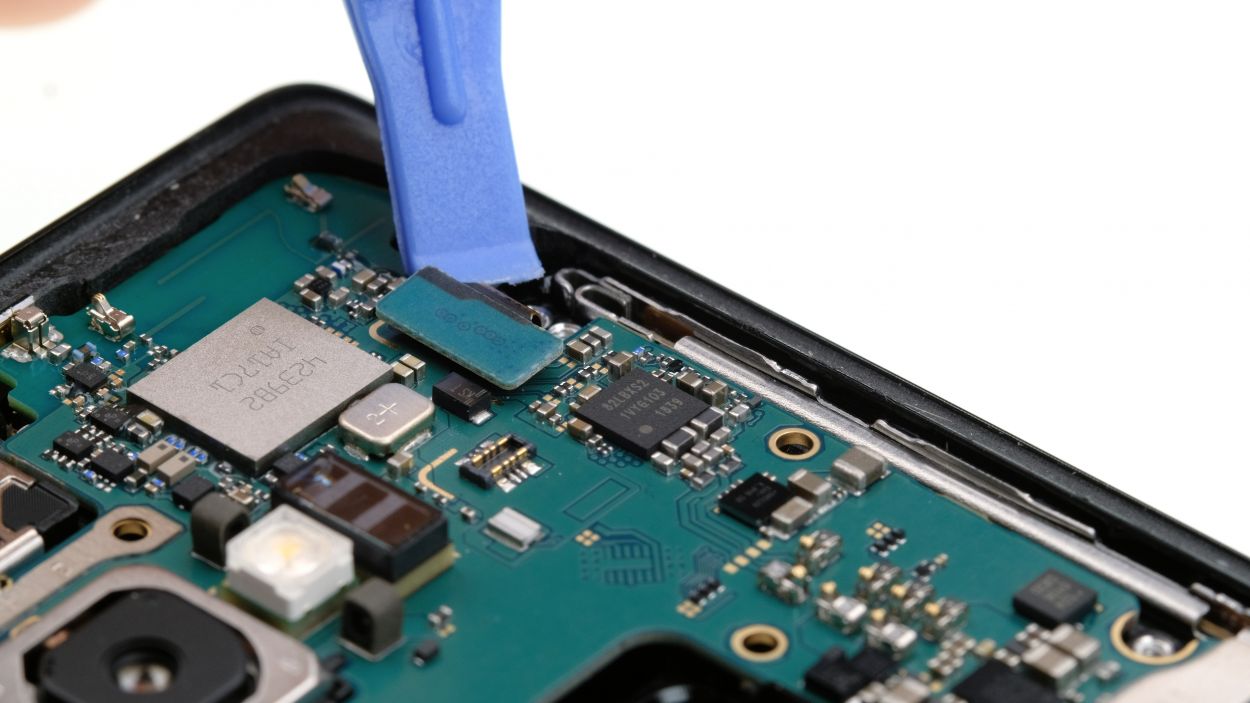
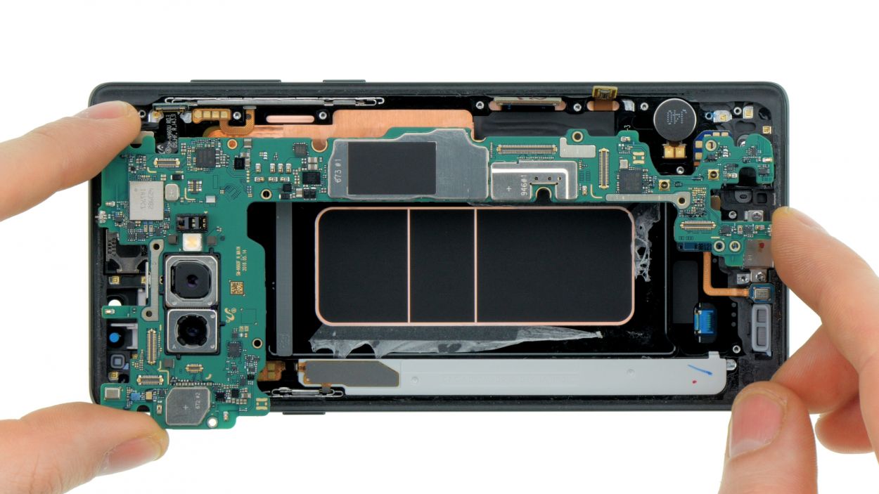
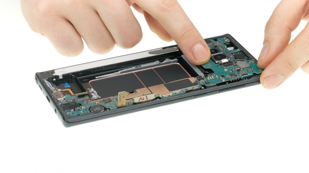
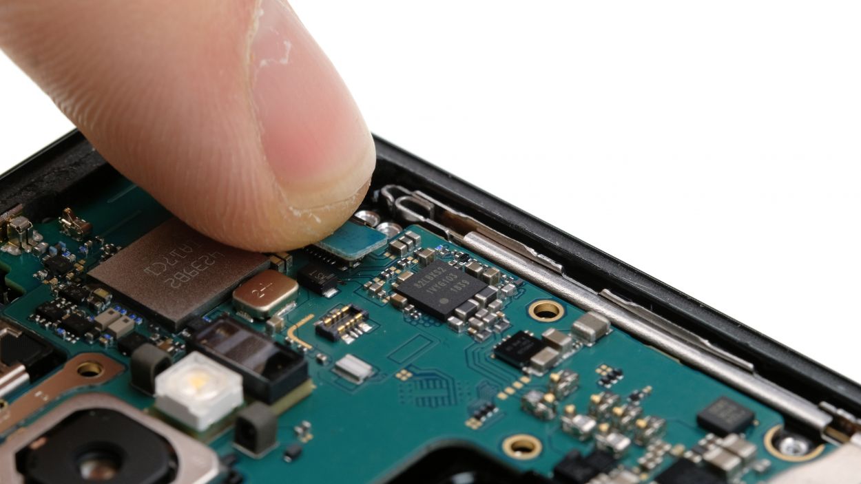
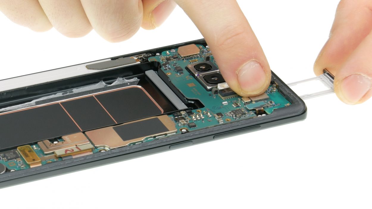
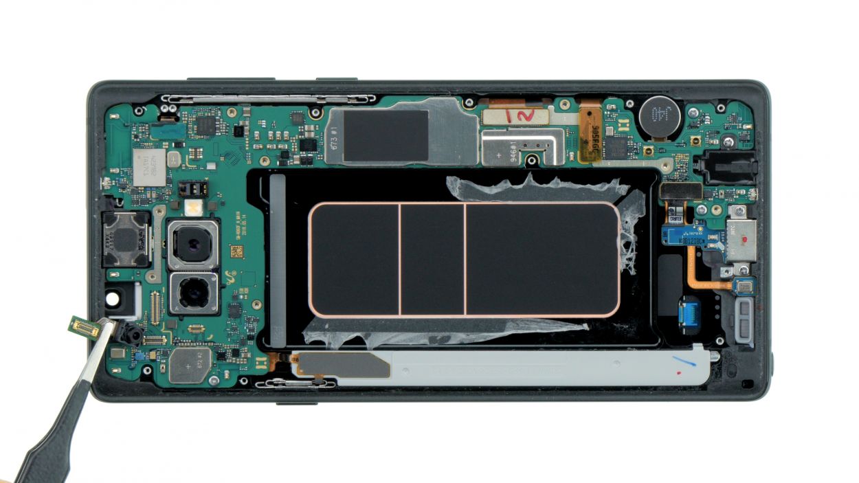
– Grab your trusty spudger and gently disconnect those highlighted contacts from the mainboard. You’ve got this!
– Next up, let’s tackle those marked screws. Unscrew them with care!
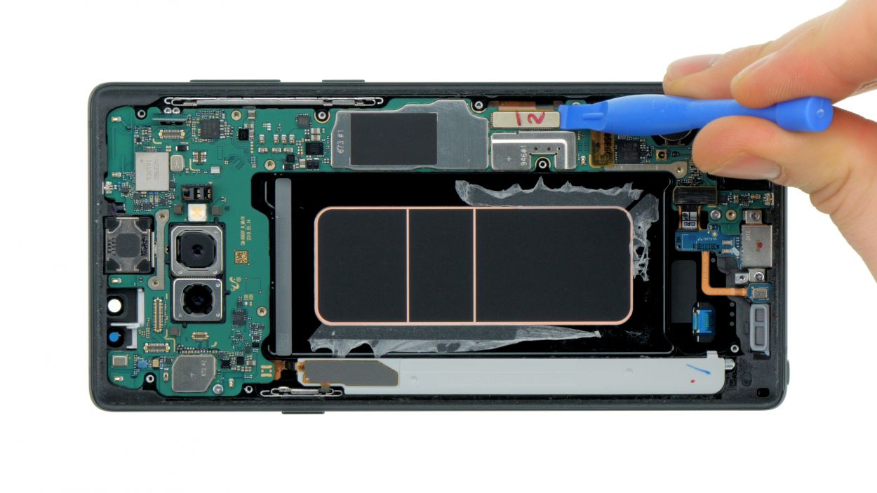
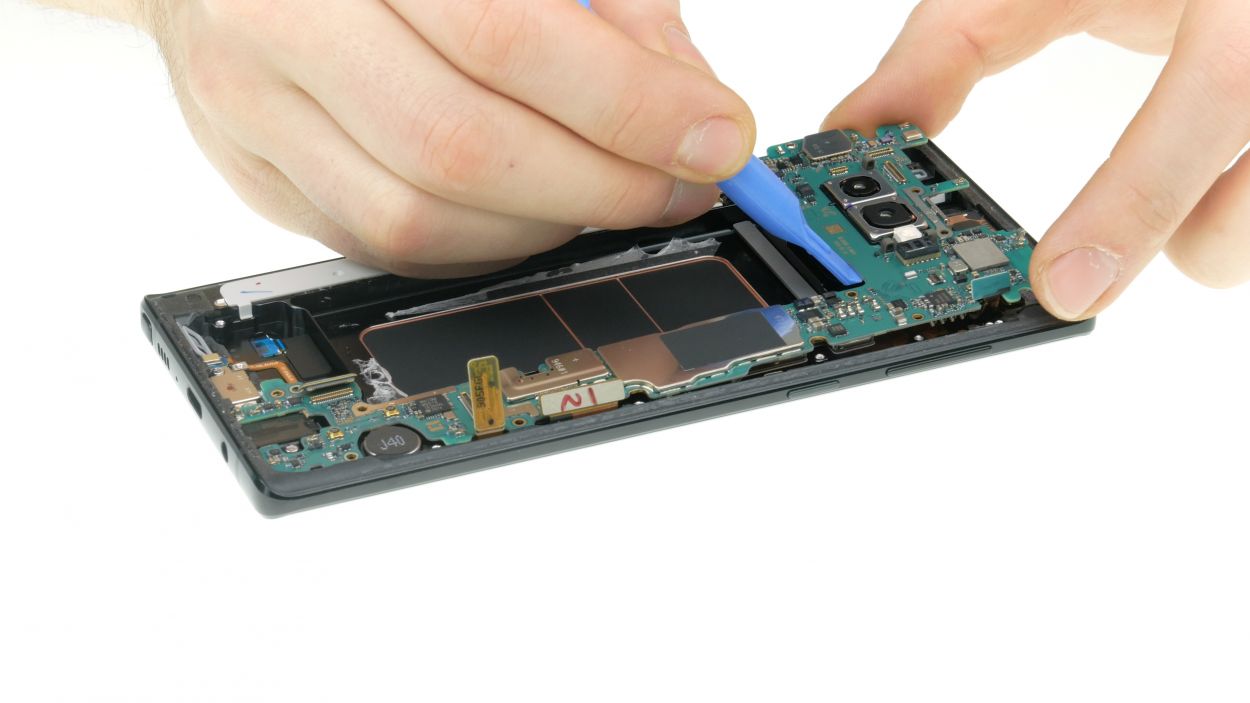
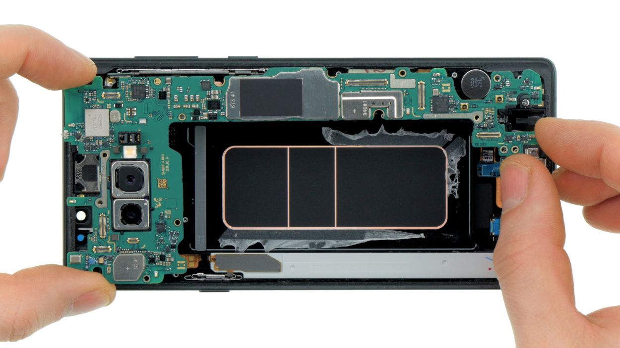
– Now it’s time to carefully lift out the motherboard. Just be mindful not to snag it on any connectors you’ve already detached.
– Once it’s free, place the motherboard in a safe spot to keep it out of harm’s way.
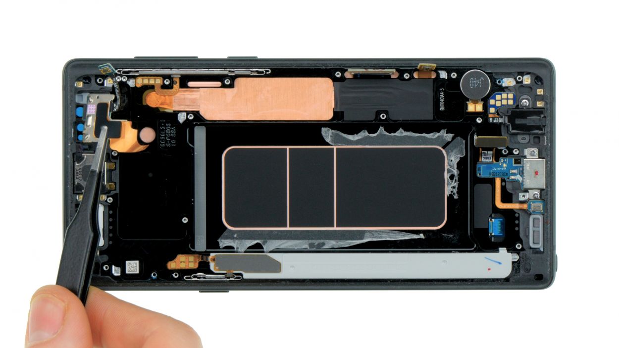
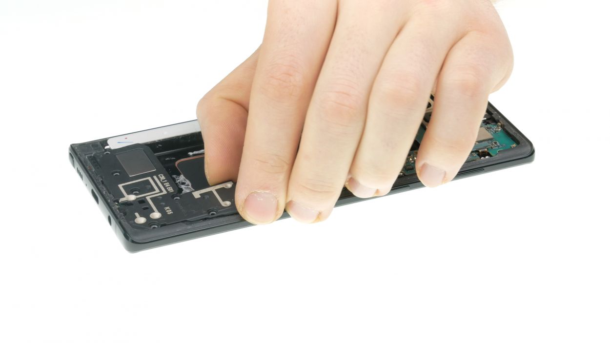
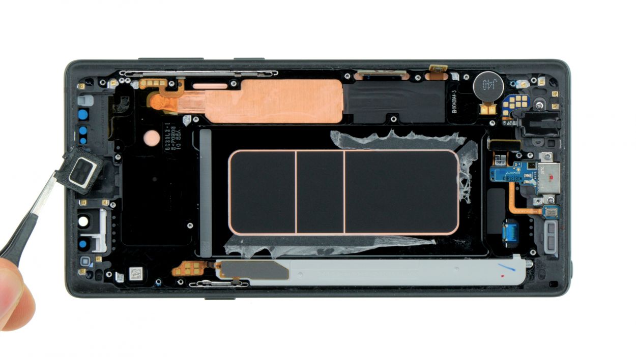
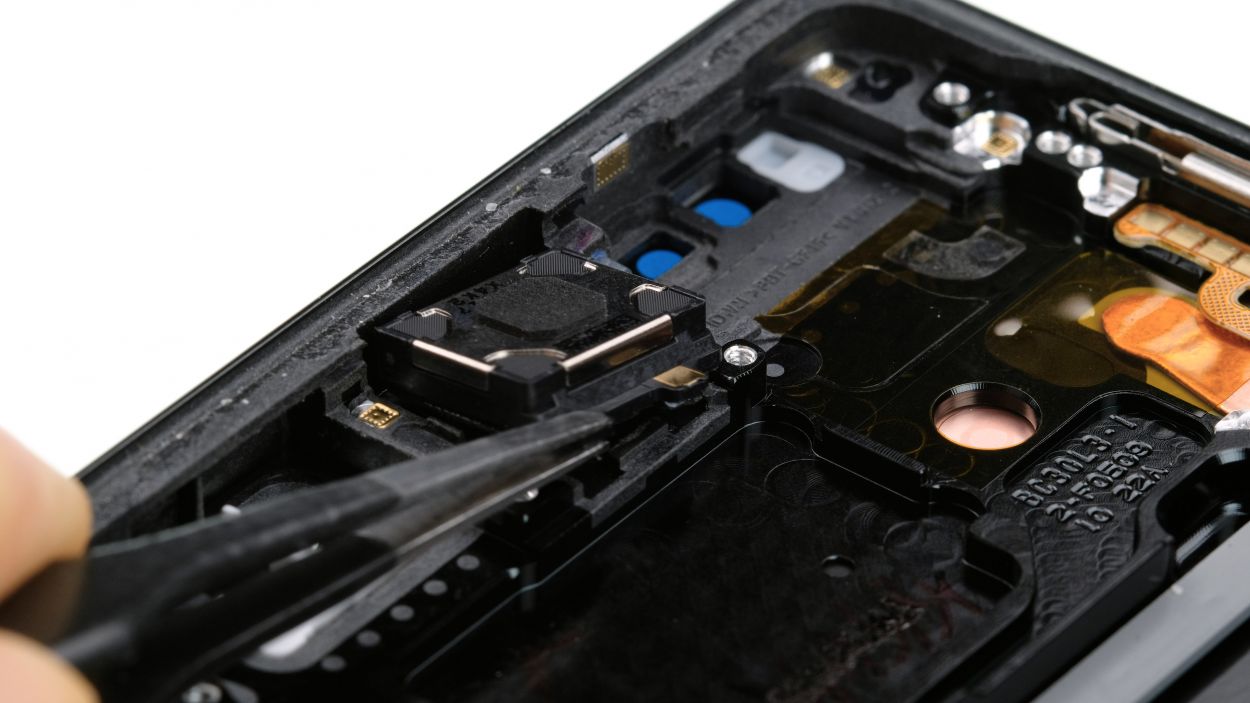
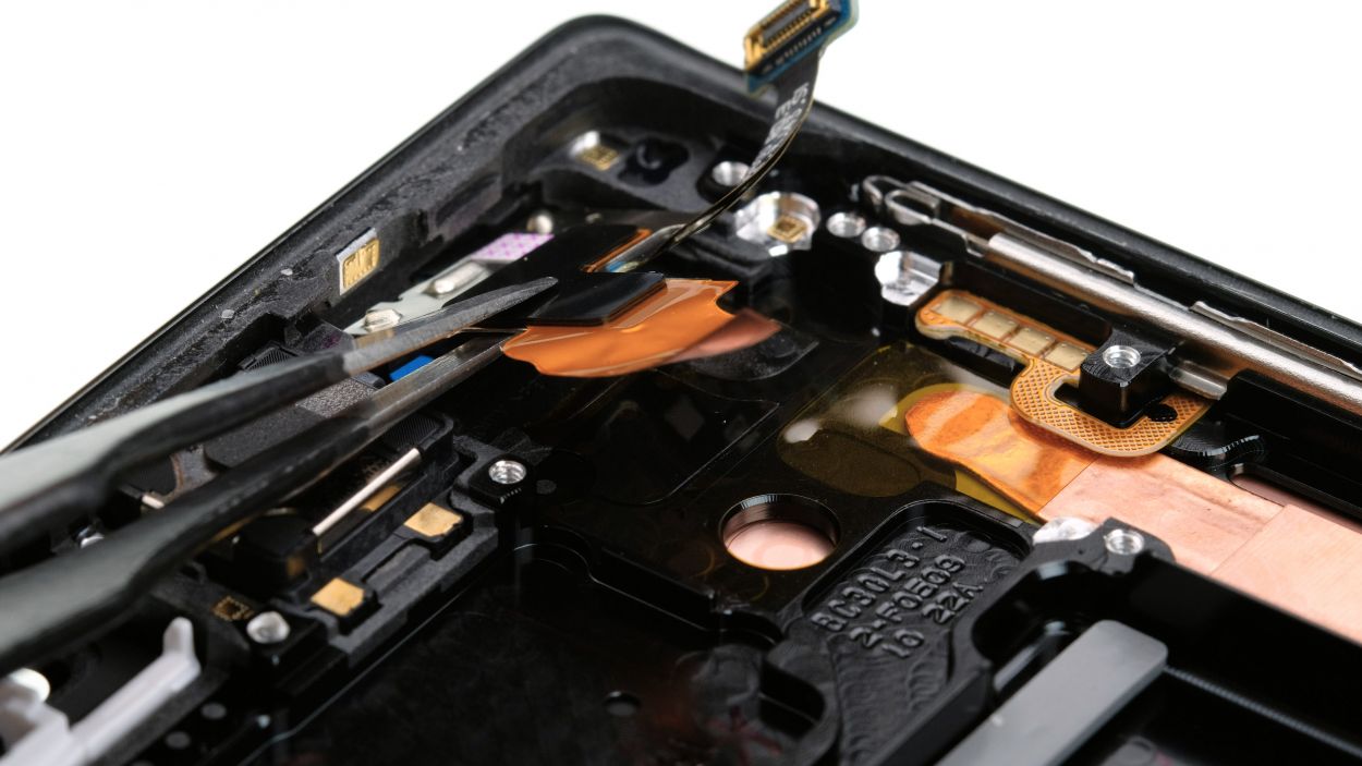
Step 12
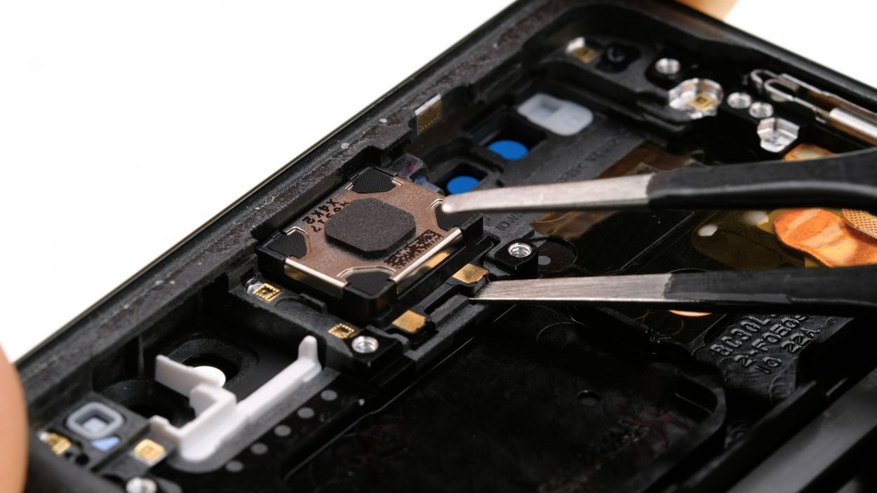

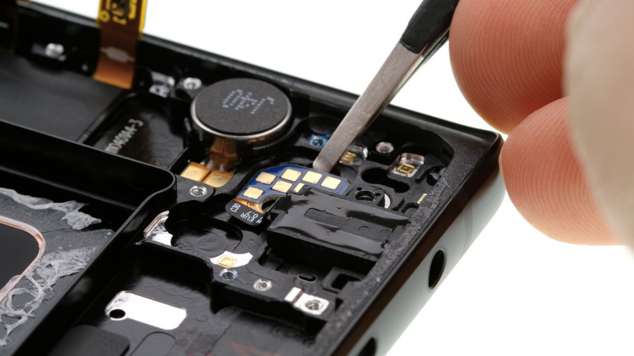
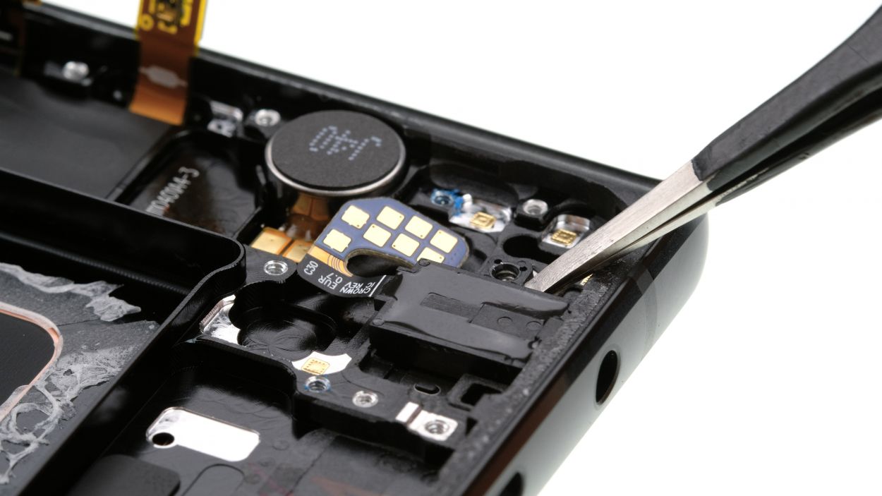
– The earpiece is snugly glued to the enclosure. Gently pry it off using a flat tool like a steel spatula. If you find yourself in a pickle, remember, you can always schedule a repair.
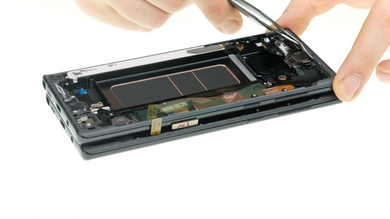
Step 13
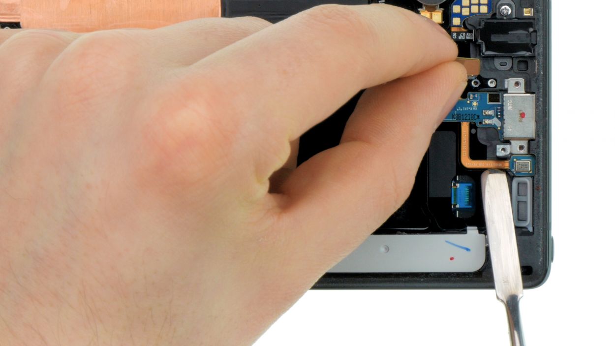
2 × 3,3 mm Phillips
– Let’s kick things off by unscrewing those marked screws! You’ve got this!
– Next up, gently loosen that thin glued flex cable for the microphone. Take your time, it’s a delicate dance!
– Now, give the USB socket a little nudge to pop it out just a tad, and then you can go ahead and remove it completely. Easy peasy!
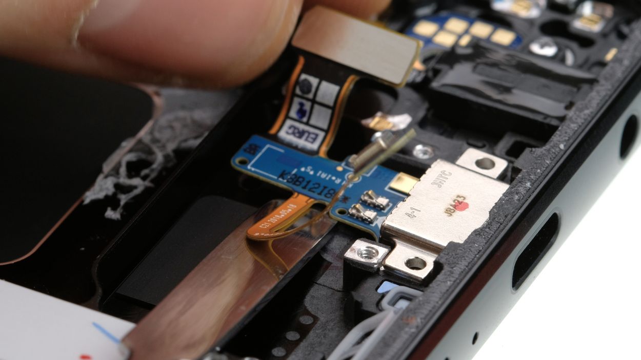
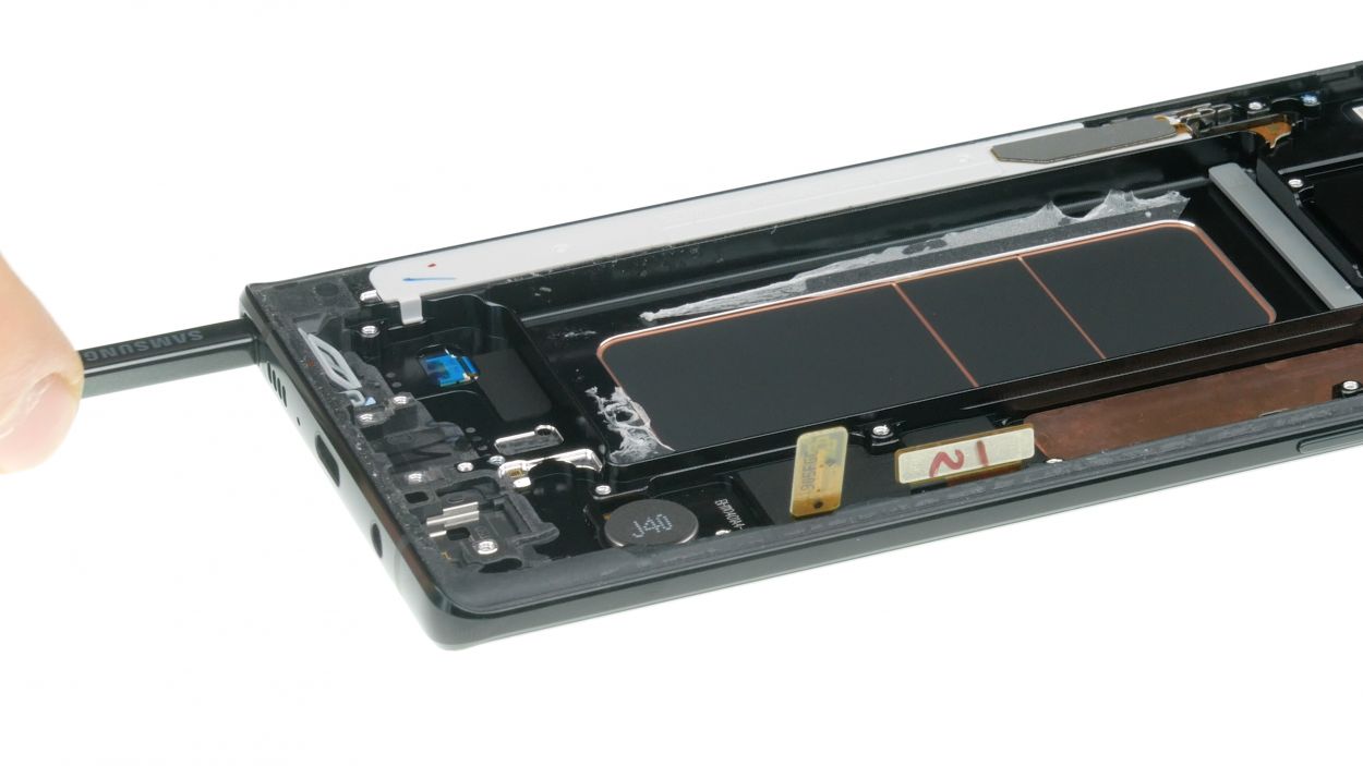
Step 14
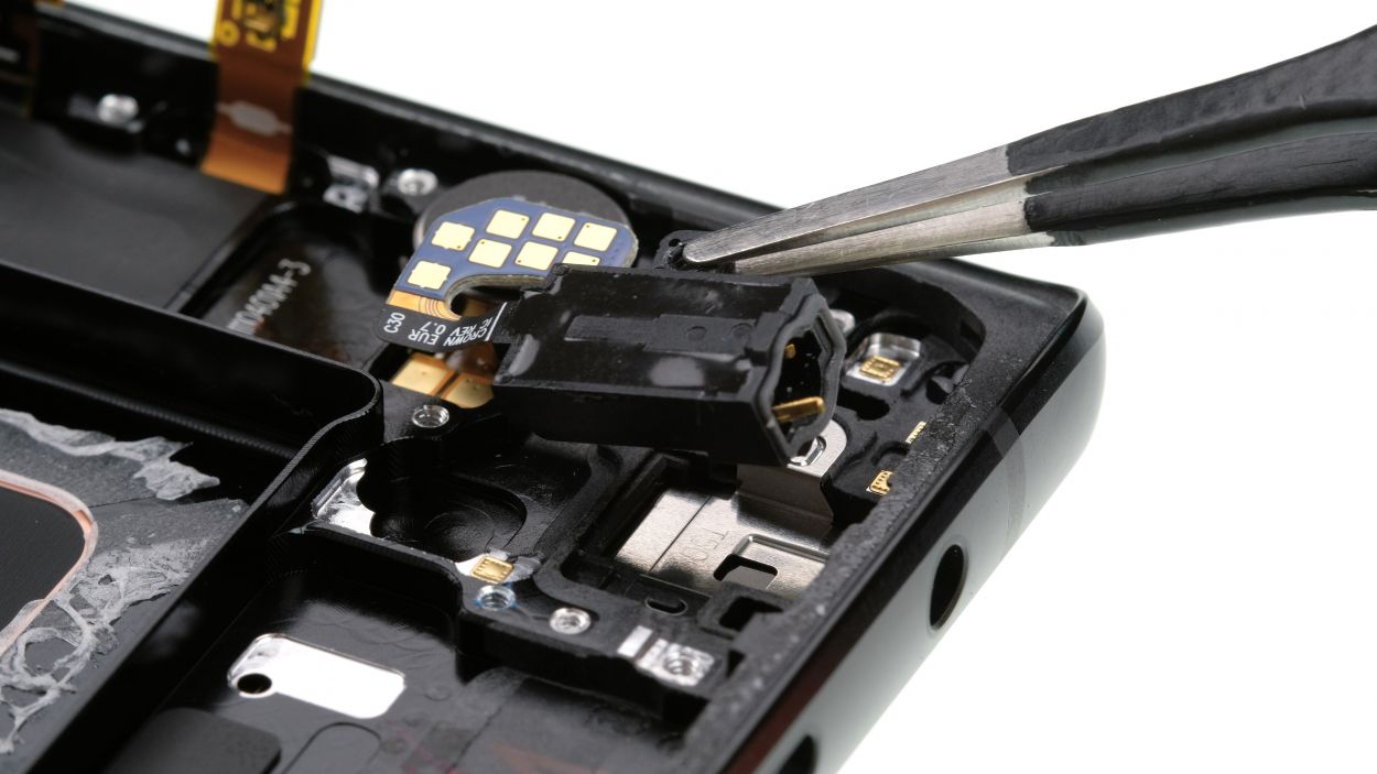
1 × 3,3 mm Phillips
– Time to get your screwdriver out! Start by loosening the screw that holds the headphone jack in place.
– Next, gently detach the thin flex cable connected to the jack. A little heat will help melt that adhesive away, making it a breeze to work with.
– Now, give the headphone jack a little lift and carefully remove it from the case. You’re doing great!
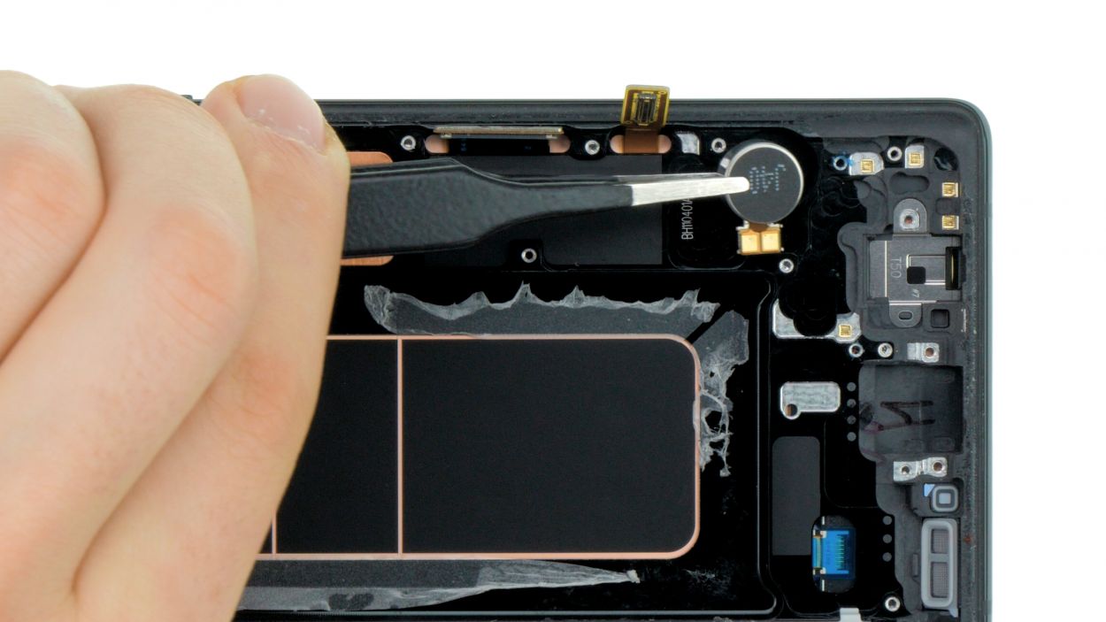
Step 15
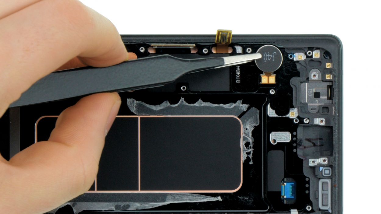
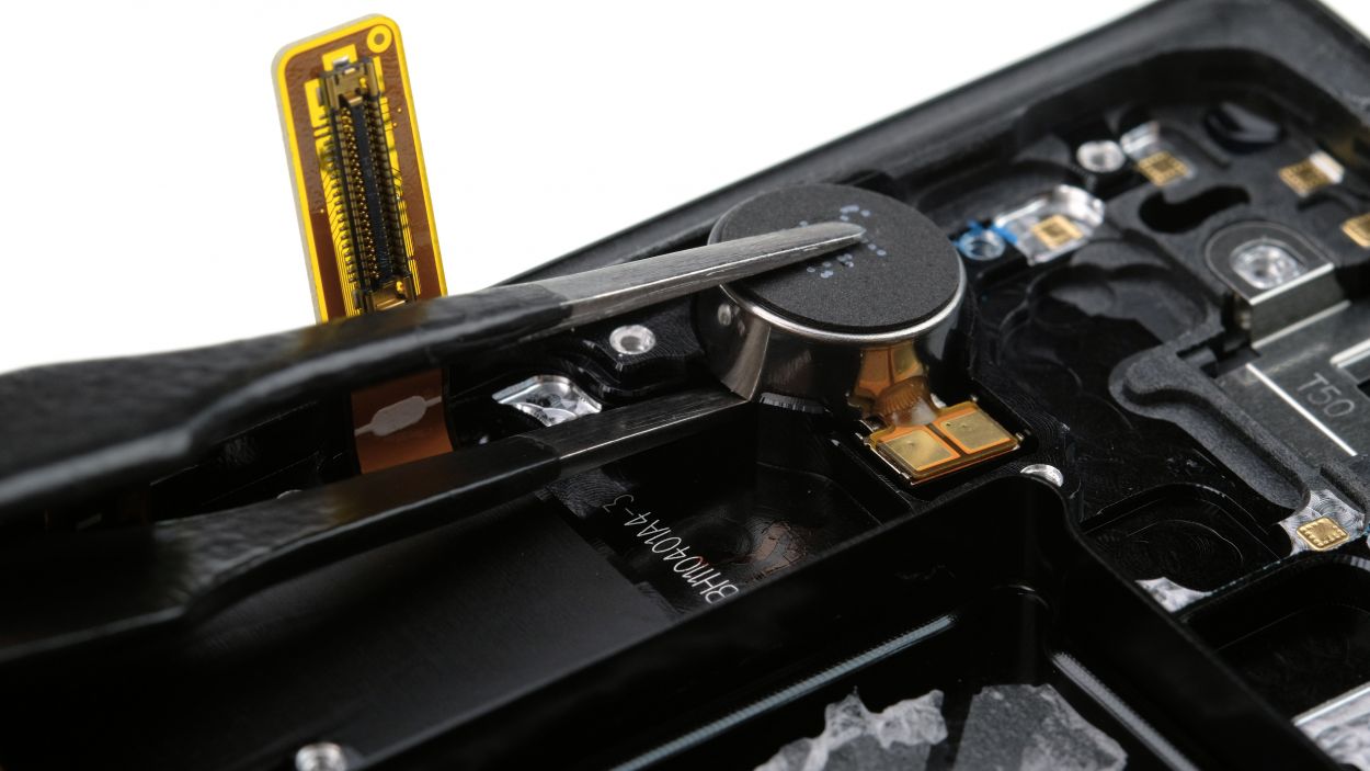
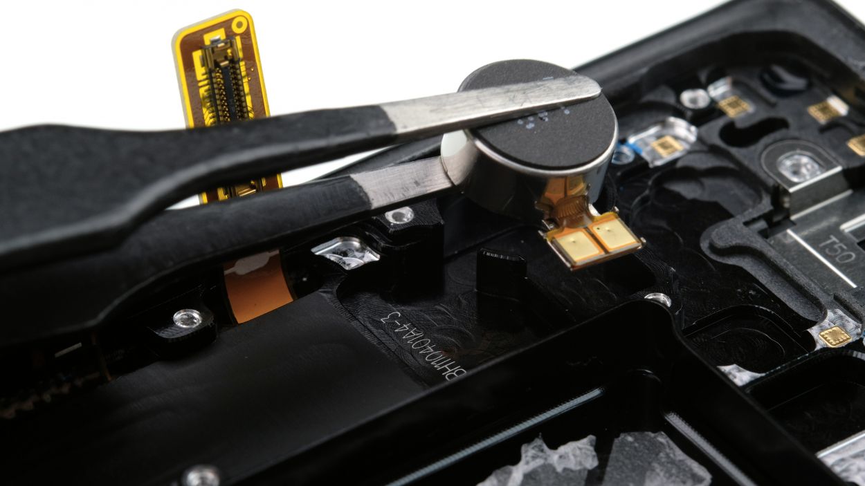
– Alright, let’s get that vibration motor out! It’s stuck on there with some glue, so gently slide your tool between the motor and the enclosure to free it up. Take your time and be careful!
– Now, go ahead and lift that motor out. You’re doing great!
Step 16
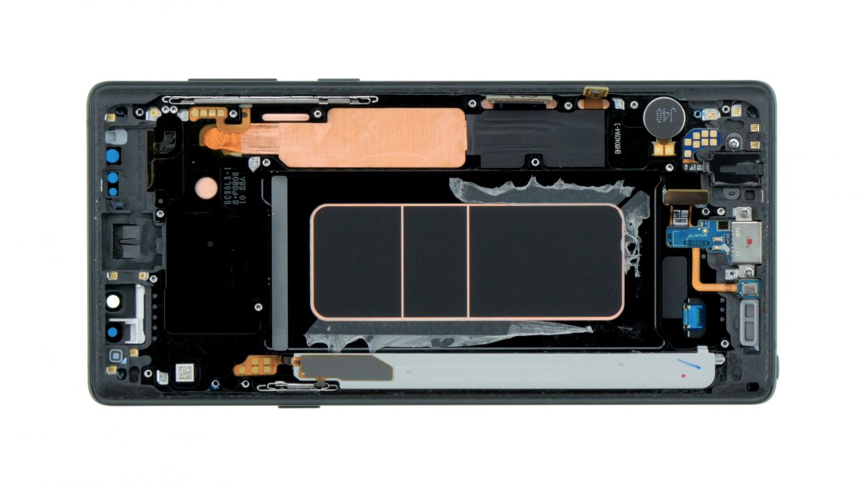
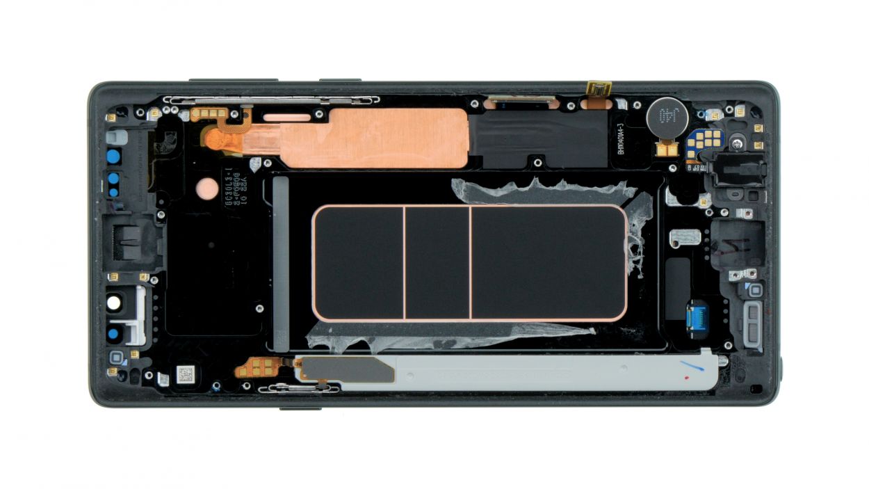
– Before diving into assembly, make sure to peel off the transparent protective film covering the adhesive surfaces and thermal pads on your new display’s enclosure. Those little films are just hanging out, waiting for their moment to shine!
– Oh, and don’t forget to rescue the S-Pen from the old display. It deserves a second chance!
Step 17
– Nestle that vibration motor snugly into the little round spot on the left side of the enclosure.
– Give it a gentle but firm press with your fingers to make sure it’s cozy in its new home.
Step 18

1 × 3,3 mm Phillips
– Let’s get that jack nestled right into the bottom of the housing.
– Give it a good press until you hear that satisfying click.
– Now, secure it with the screw and connect the flex cable to finish the job!
Step 19

2 × 3,3 mm Phillips
Ensure that the component sits flush with the housing for a seamless finish.
– Pop that USB board back in place!
Step 20
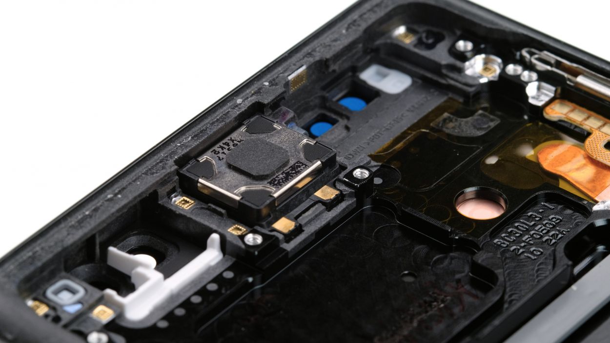
– Carefully place the earpiece back into its cozy little home.
– Give it a gentle press to help the glue do its magic and stick like a champ.
Step 21
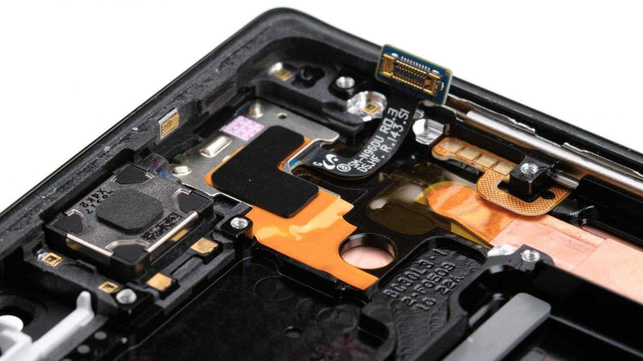
– Gently slide the sensor cable into its cozy little spot at the top edge of the enclosure.
– Give the sensor and the orange layer a friendly press with your finger to help the glue bond once more.
Step 22
Display connector
USB connector
Button connector
3 × 3,3 mm Phillips
– Place the board snugly in the device, like tucking in a cozy blanket.
– Double-check that no cables or connectors are hiding underneath the board – we want everyone to be comfy!
– Secure the board in place with those two screws, just like fastening your seatbelt for safety.
– Now, it’s time to reconnect the marked contacts to the board. Let’s make those connections happen!
Step 23
If your SIM holder is feeling a bit stubborn and isn’t sliding in just right, it might be a sign that the mainboard isn’t snugly in place yet. No worries, just give it a little check!
– Insert the SIM card tray back into your device. Make sure the tray is positioned properly.If the SIM holder is stuck and cannot be inserted properly the mainboard is probably not yet seated correctly.
Step 24
Camera connector
Sensor connector
– Carefully slide the front camera and sensor into the slot at the top of the enclosure, and make sure to reconnect those little connectors snugly.
Step 25


7 × 4,0 mm Phillips
– Alright, let’s get that speaker snug at the bottom of the enclosure.
– Give it a gentle press with your fingers until you hear that satisfying click as it locks into place.
– Now, it’s time to bring back those marked screws and secure everything in place.
Step 26

Step 27
Battery connector
– Attach the battery to the motherboard. Firmly press the connector onto the motherboard until you hear that satisfying click, letting you know it’s snug and secure.
Step 28
11 × 4,0 mm Phillips
– Carefully place the cover with the antenna back into the enclosure, making sure to hook it onto the top first.
– Now, give that cover a gentle press with your fingers until you hear a satisfying click all around.
– Time to secure those Phillips screws and make everything nice and snug!
Step 29
– Before you snap that back cover into place, take a moment to check out the adhesive. It should be sitting nice and even along the edge, allowing the back cover to fit snugly. If there’s any extra glue hanging around, go ahead and clean that up!
Step 30
Fingerprint connector
– First things first! Before you seal up that back cover, make sure to connect the fingerprint sensor. It’s a little step that makes a big difference!
– Grab a plastic tool to help you reach that connector. You’ve got this!
Step 31
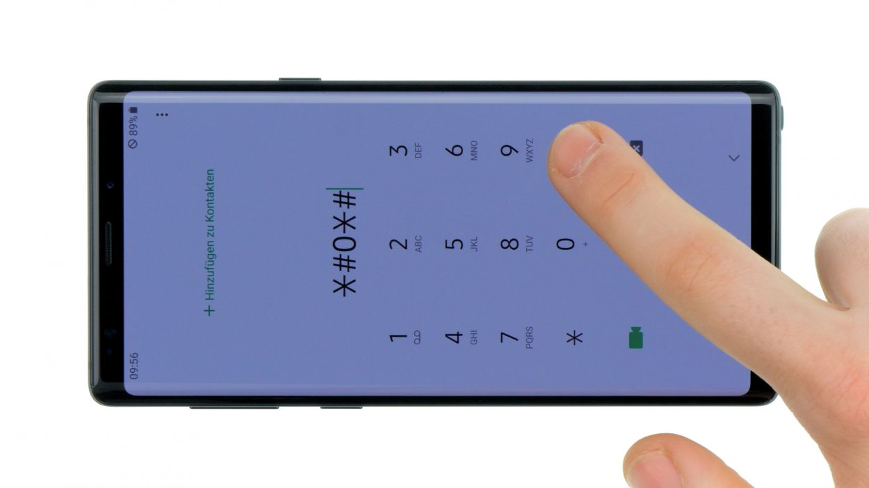
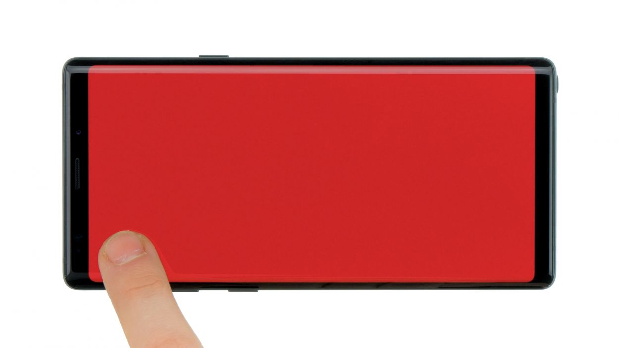
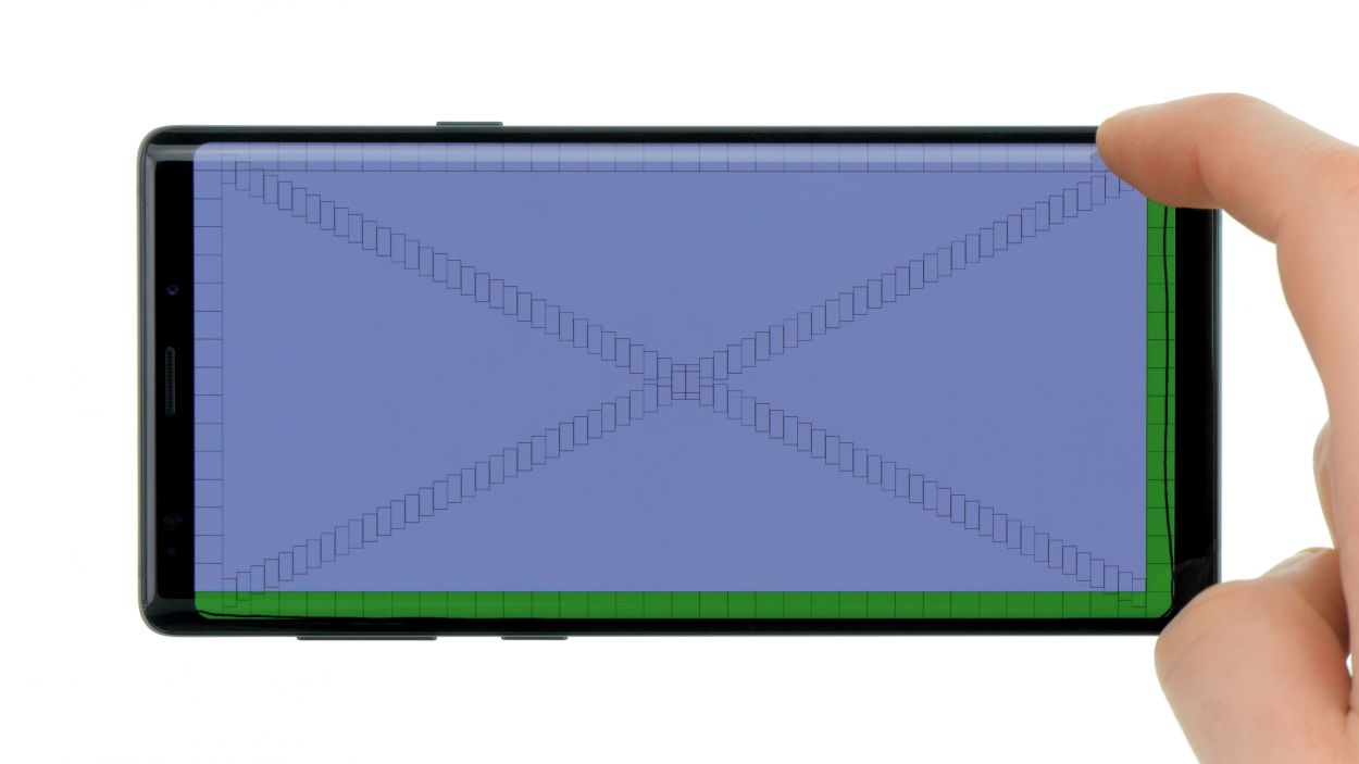
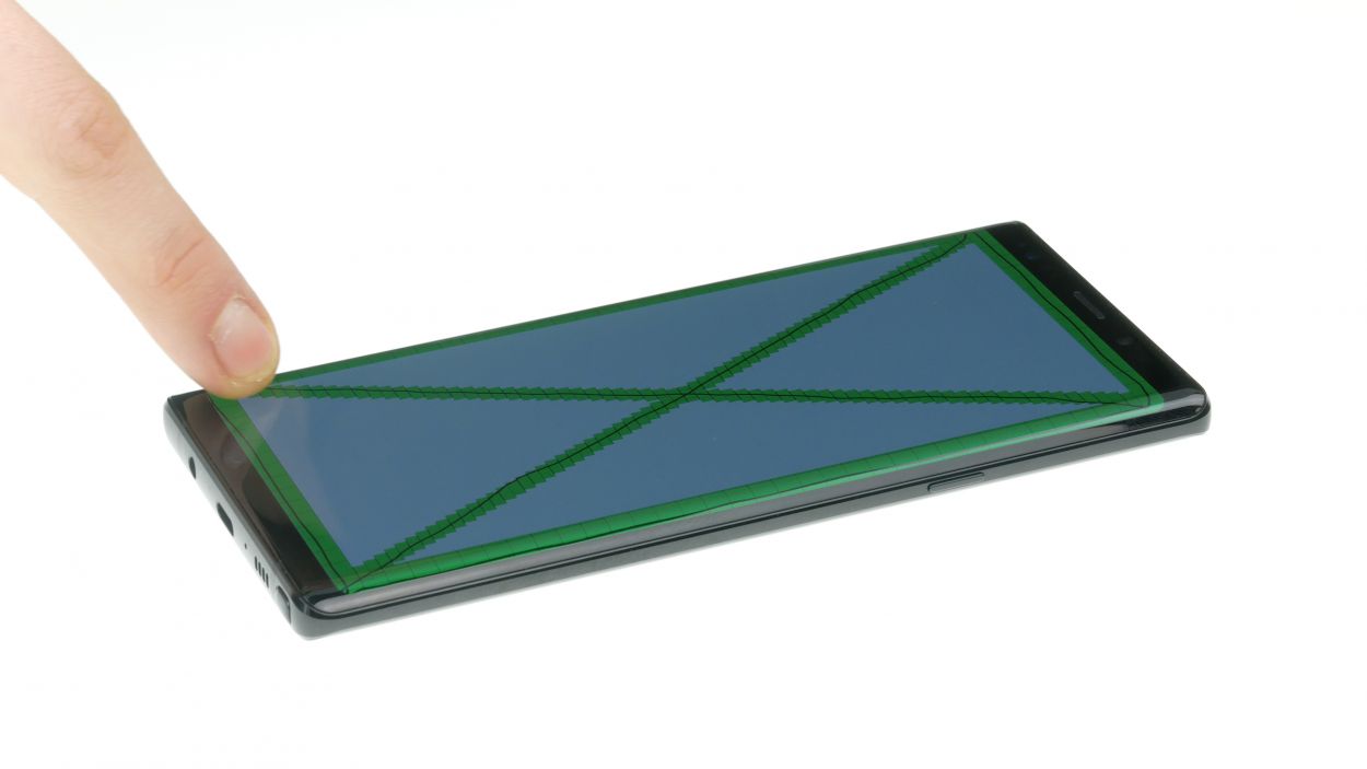
– Fire up your Galaxy Note 9 and dive into the built-in test mode for a little troubleshooting fun!
– To enter the test mode, just dial *#0*# and get ready to roll.
– Follow the prompts and give the screen, cameras, and sensors a good test drive!
Step 32
Feeling crafty? Give your device a little warmth with some hot air! After that, grab a couple of books and let them sit on top to help the glue bond like best friends. It’s a simple trick to make sure everything sticks together nicely!
– Carefully place the back cover back where it belongs, just like a puzzle piece fitting into its spot.
– Give the back cover a gentle press all around to help that glue do its job and stick like a champ!