DIY Guide to Replace Huawei P8 Lite Screen
Duration: 75 min.
Steps: 24 Steps
In this guide, we’re here to help you tackle the task of replacing the display unit on your Huawei P8 lite. If you’re dealing with a cracked screen, an unresponsive touchscreen, or an LCD that’s decided to play hide and seek, this repair is just what you need. Let’s get started and bring your device back to life!
Step 2
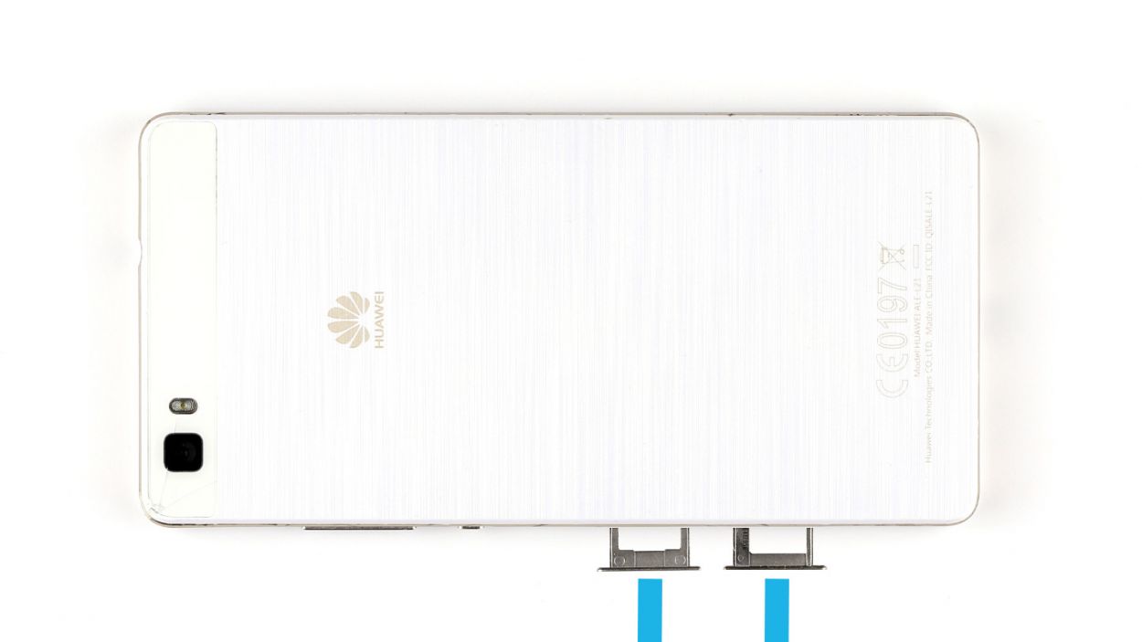
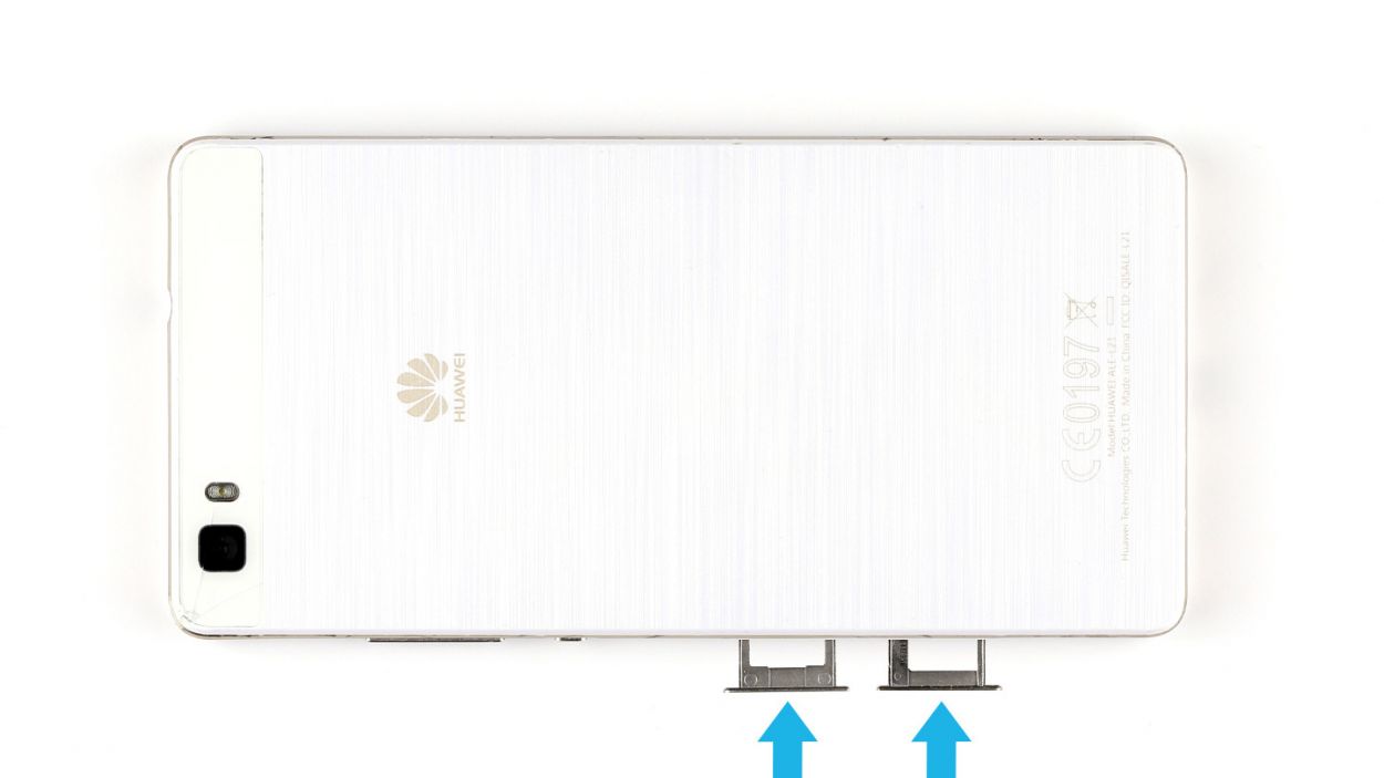
– Remove the two trays for the SIM and microSD cards from the enclosure by pressing a SIM Tool or paperclip into the little hole until the tray comes out. Then remove both trays and the cards.
Step 3
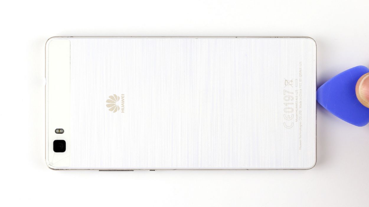
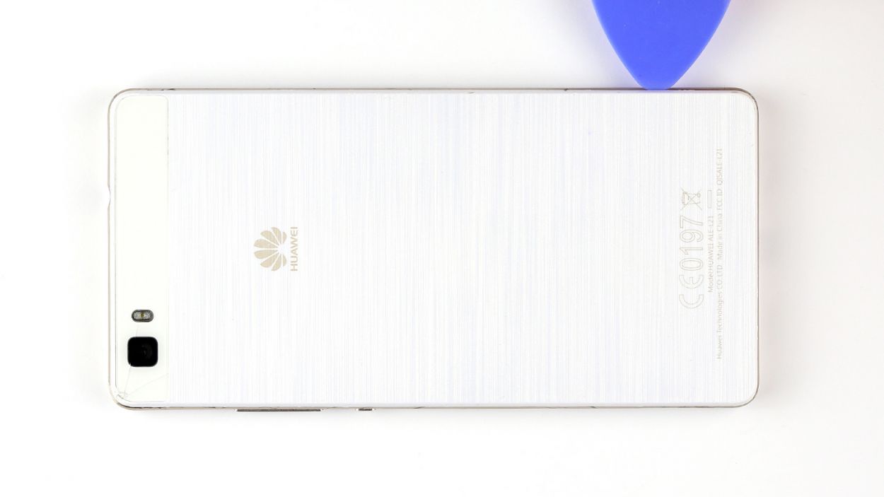
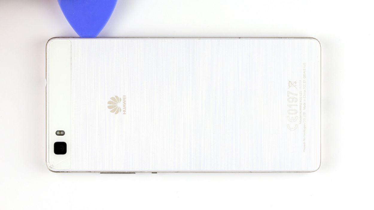
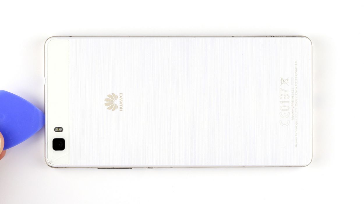
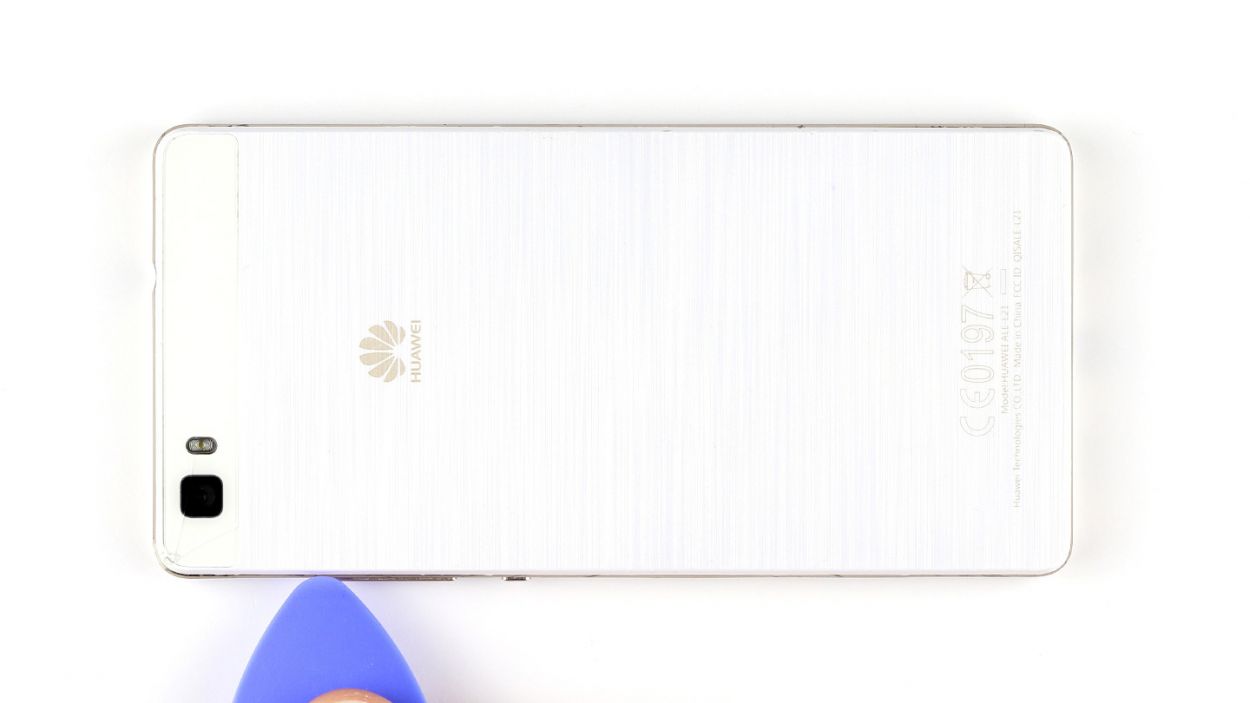
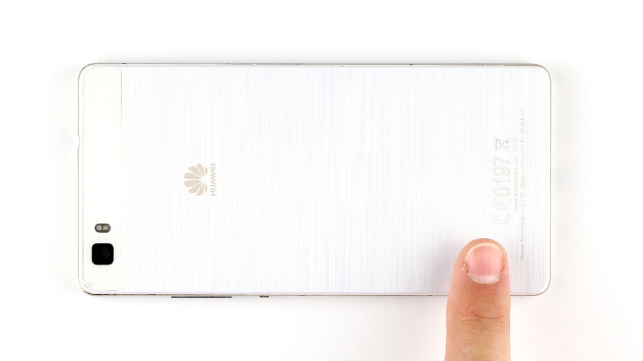
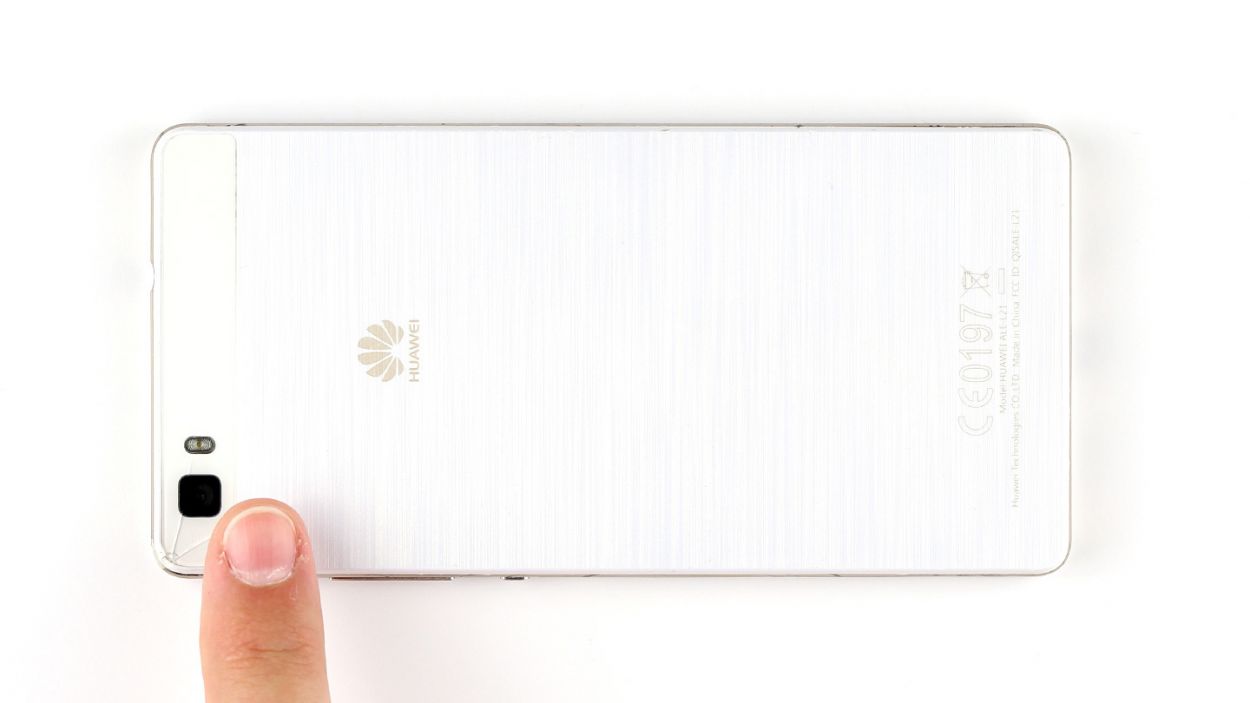
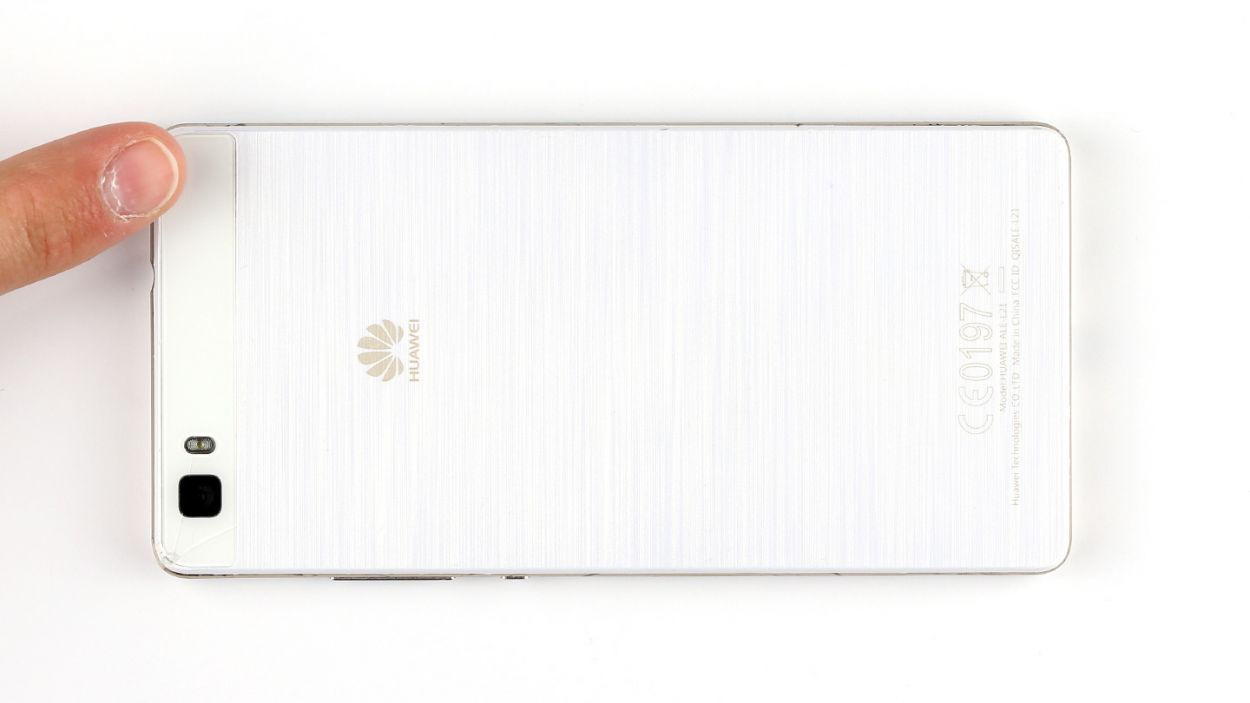
– Gently pry off the back cover from the enclosure frame. It’s secured at several points, so you’ll need to work those hooks loose. Grab a pick and slide it between the back cover and the frame, and keep going until you’ve released it all the way around the device.
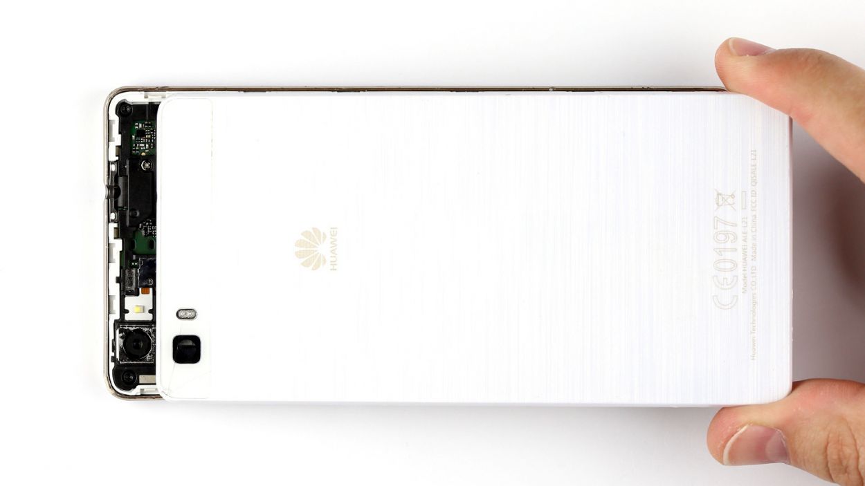
– Now, lift the back cover off your device with care.
Step 4
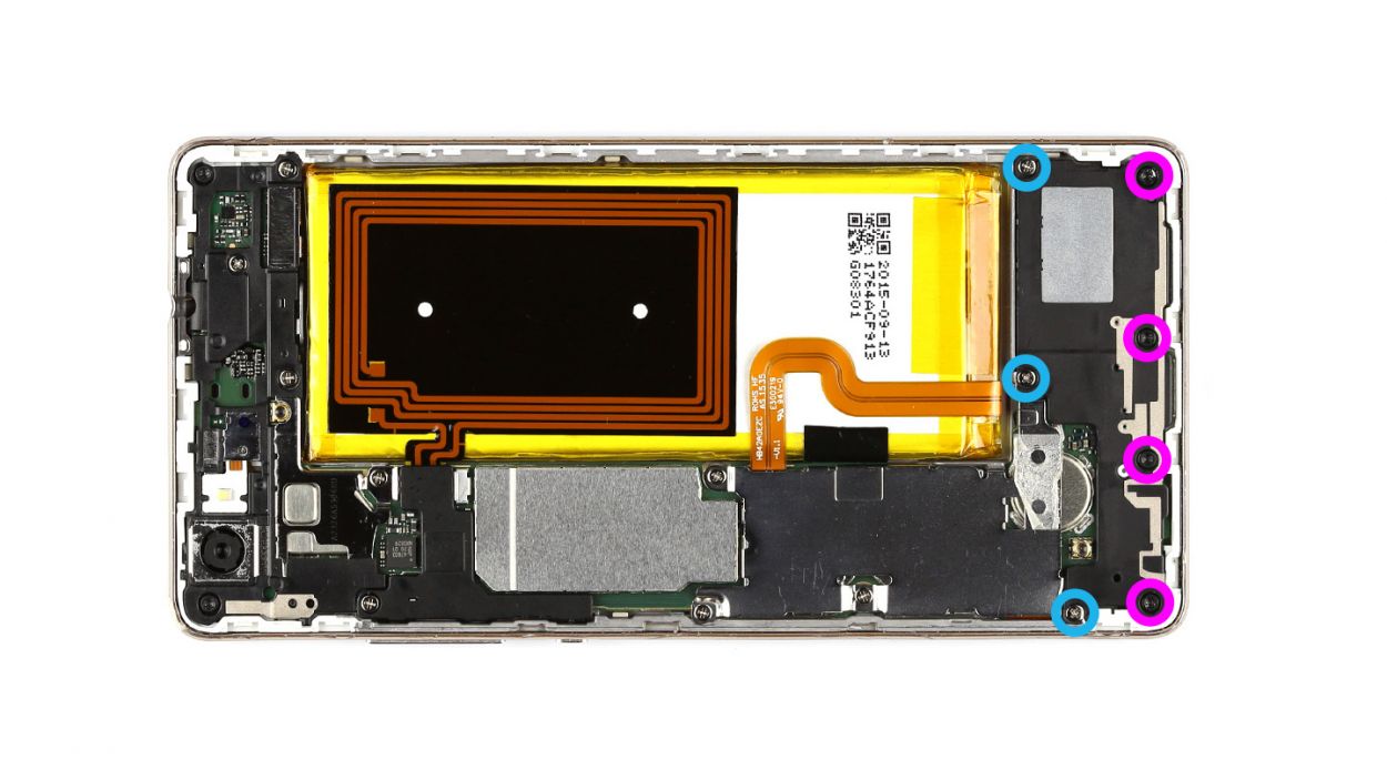

– Let’s kick things off by unscrewing those seven little screws that are keeping the speaker snug in its spot. You’ll need 3 of those 2.7 mm PH00 Phillips screws and 4 of those 3.7 mm T5 Torx screws. Easy peasy!
– Once those screws are out of the way, gently lift the speaker out of your device. You’ve got this!
Step 5

– First up, let’s tackle those three screws. Grab your trusty PH00 Phillips screwdriver and remove those 3 x 2.7 mm screws like a pro.
– Next, gently take off the silver cover from your device. It’s like peeling back the layers to reveal the magic inside!
– Now, it’s time to disconnect the battery contact from the PCB. Carefully slide your tool underneath the contact and lift it up. Remember, we want to keep everything intact, so be gentle and avoid any damage to the board.
– Finally, let’s disconnect the display contact in the same smooth manner. You’ve got this!
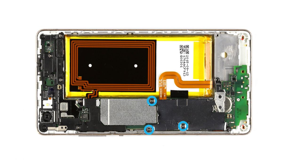
Step 6


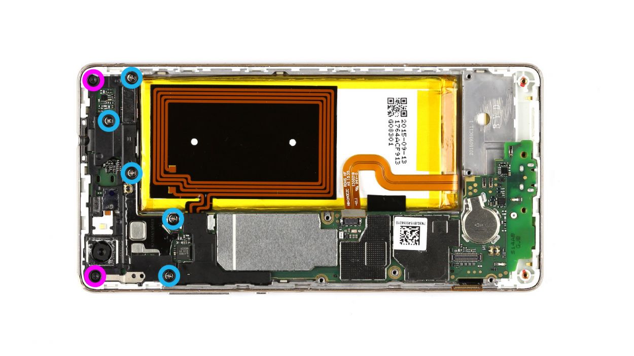
– First things first, let’s tackle those seven screws holding the cover in place! You’ll need a 5 x 2.7 mm PH00 Phillips screw and a couple of 2 x 3.7 mm T5 Torx screws to get started.
– The cover is a two-part wonder! Gently lift off the larger upper cover using a trusty pair of tweezers.
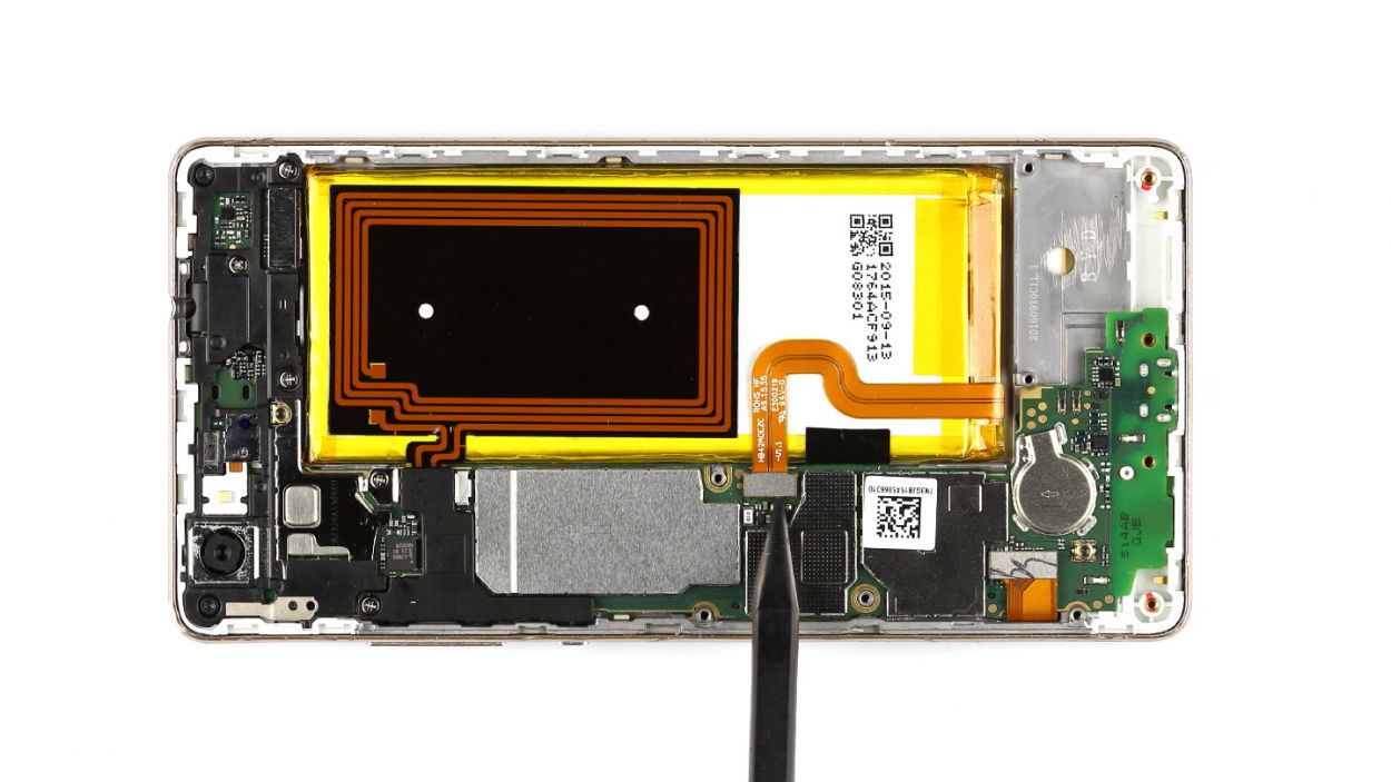
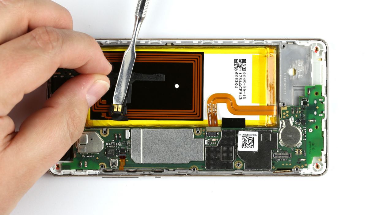
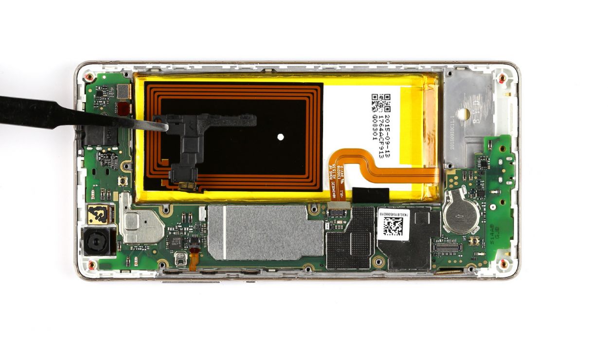
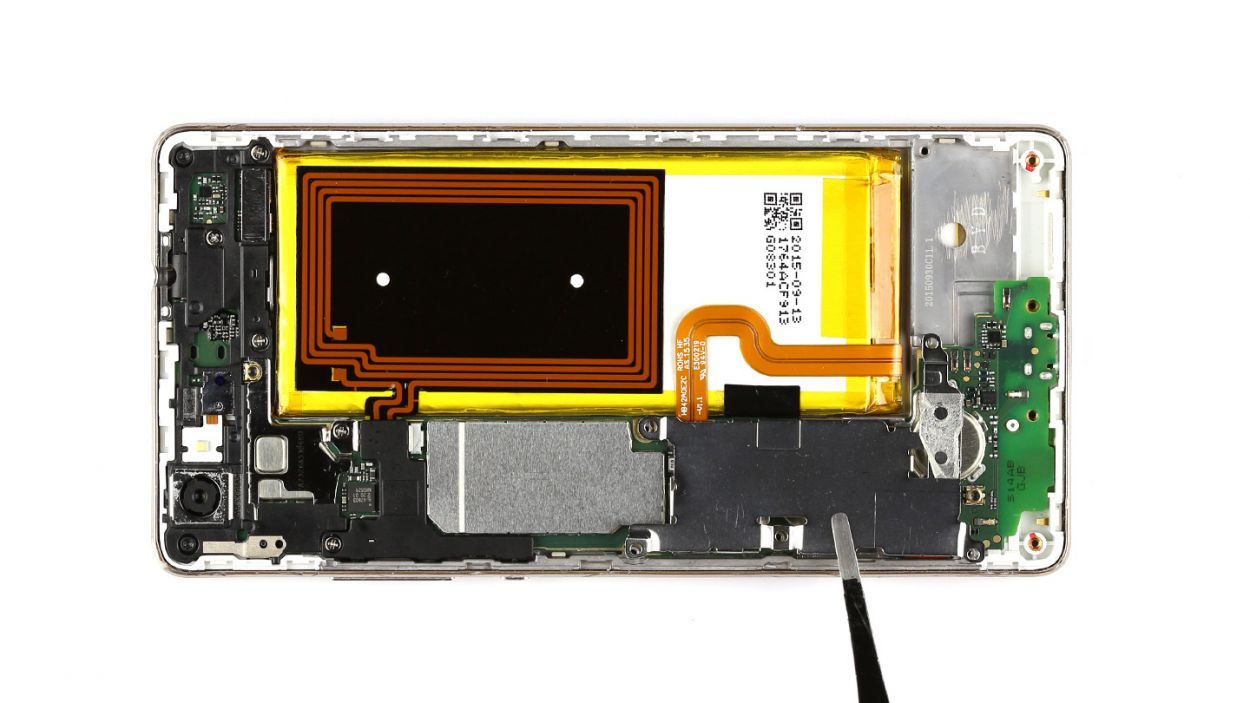
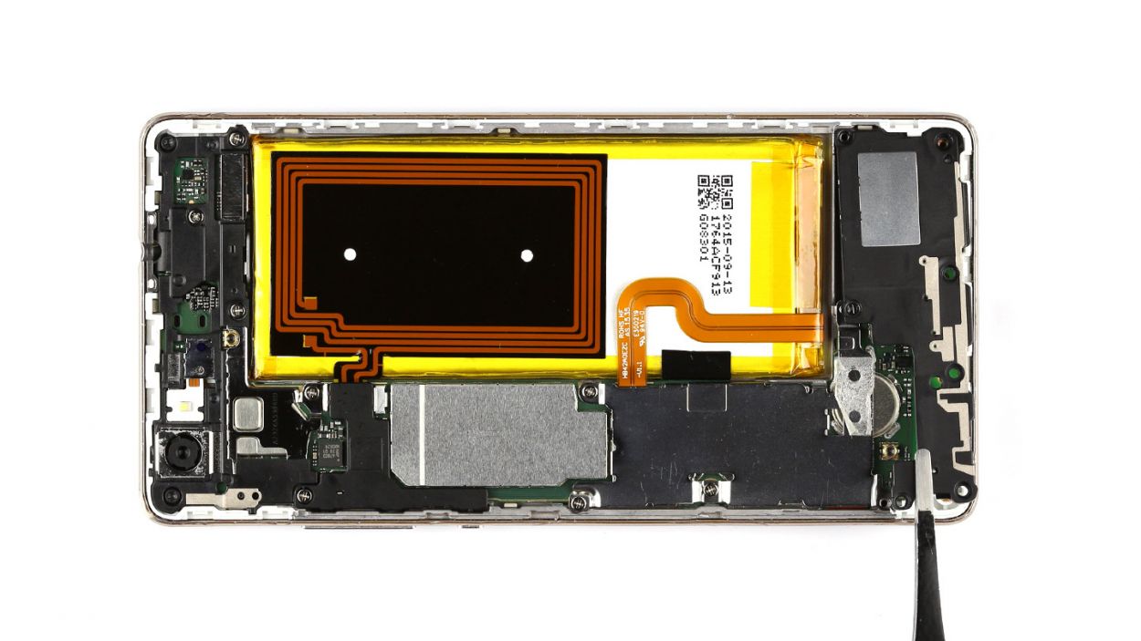
– Now, flip that cover over! The NFC antenna’s contact is glued to the bottom of the smaller cover, and it’s time to disconnect it.
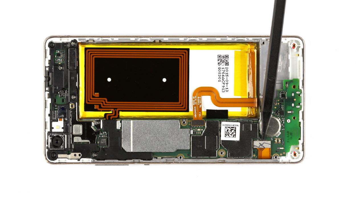
– With a little finesse, use a steel laboratory spatula to carefully pry the contact away from the cover. Easy does it!
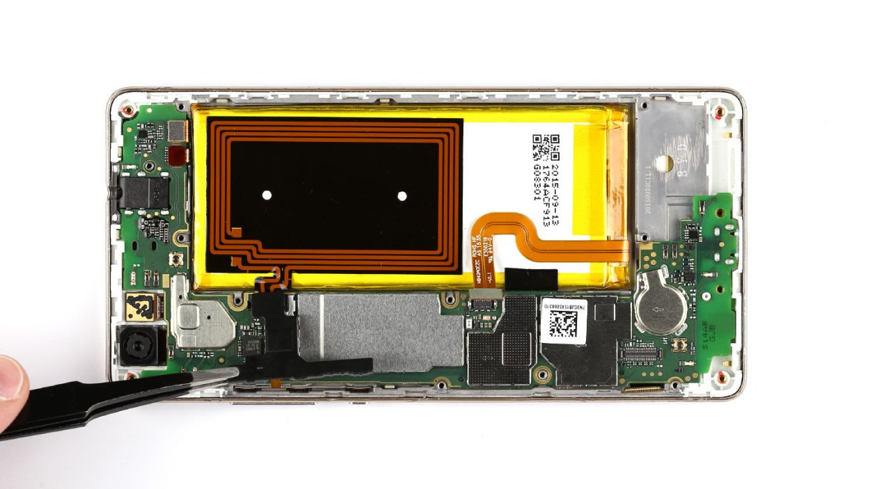
– Don’t forget to remove the little cover too!
Step 7
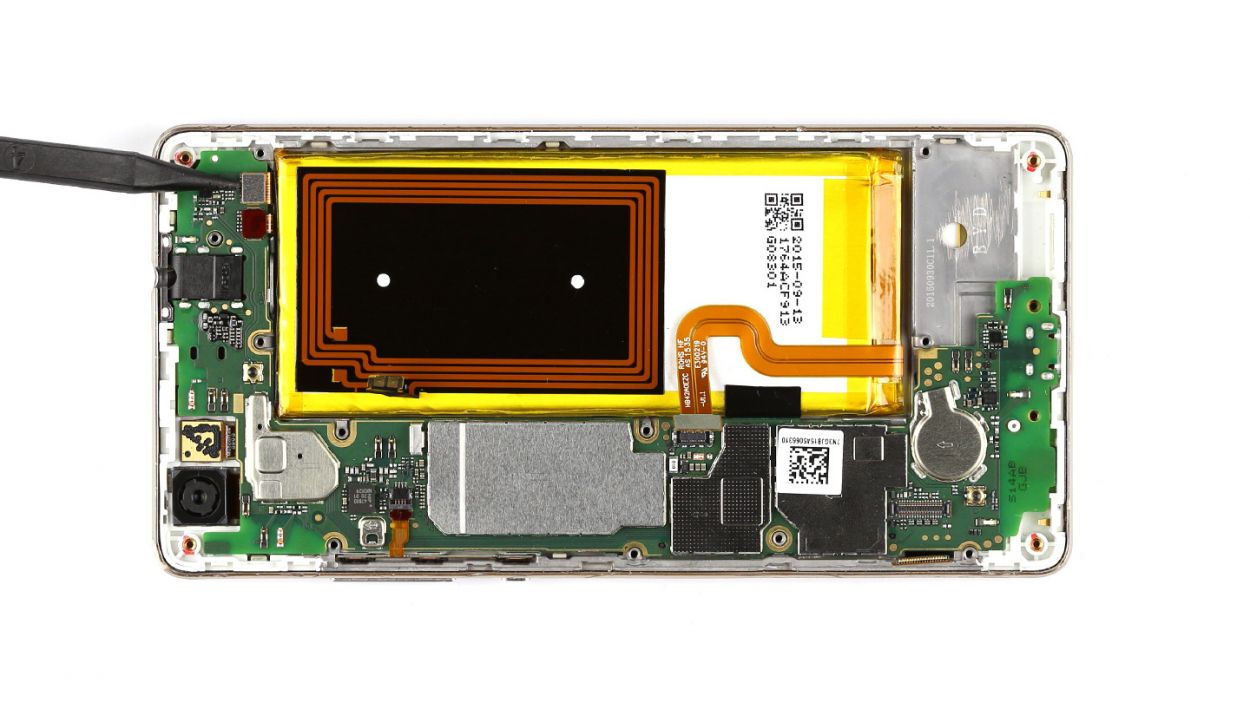

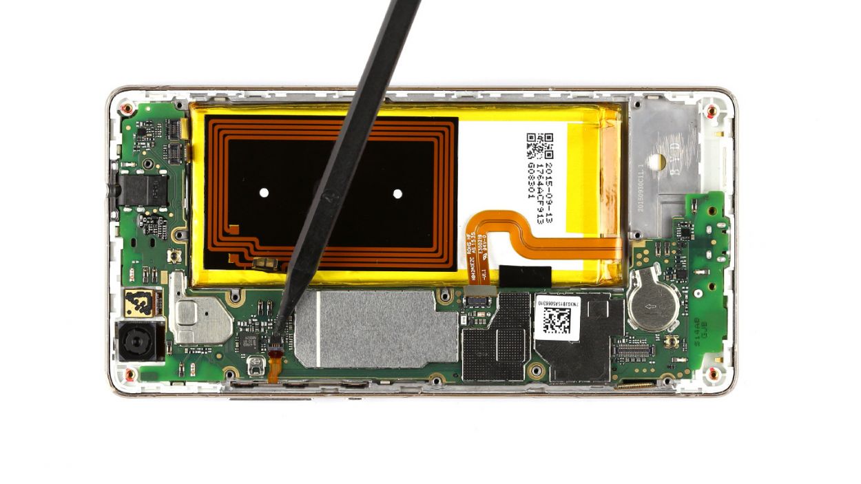


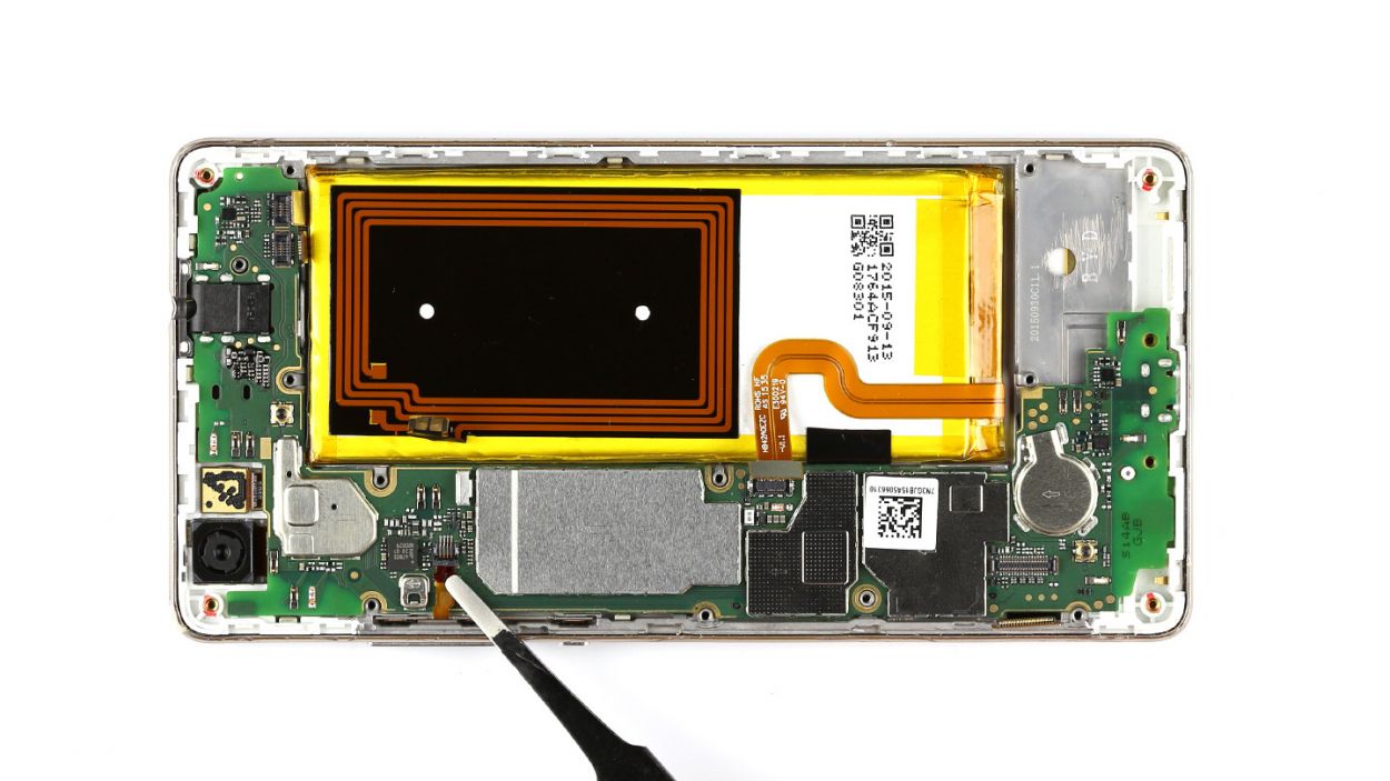
– First things first, let’s disconnect that touchscreen contact from the motherboard. Slide your tool underneath and give it a gentle lift. You’ve got this!
– Next up, it’s time to disconnect the sensor cable in the same smooth manner. Keep it easy and breezy!
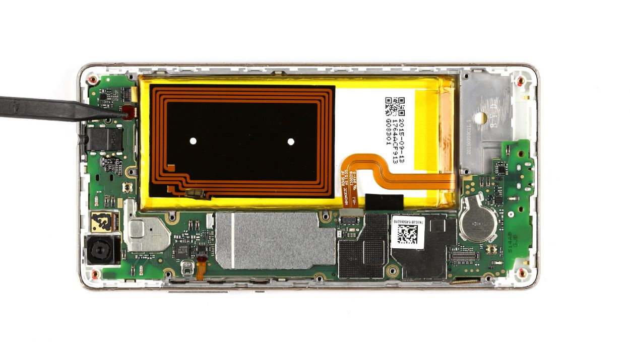
– The control button contact is held down by a tiny bracket. Lift that little guy up to free the contact, then carefully pull out the cable. Remember, be gentle—no tug-of-war here!
– Now, let’s remove those control buttons from the device. You’re doing great!
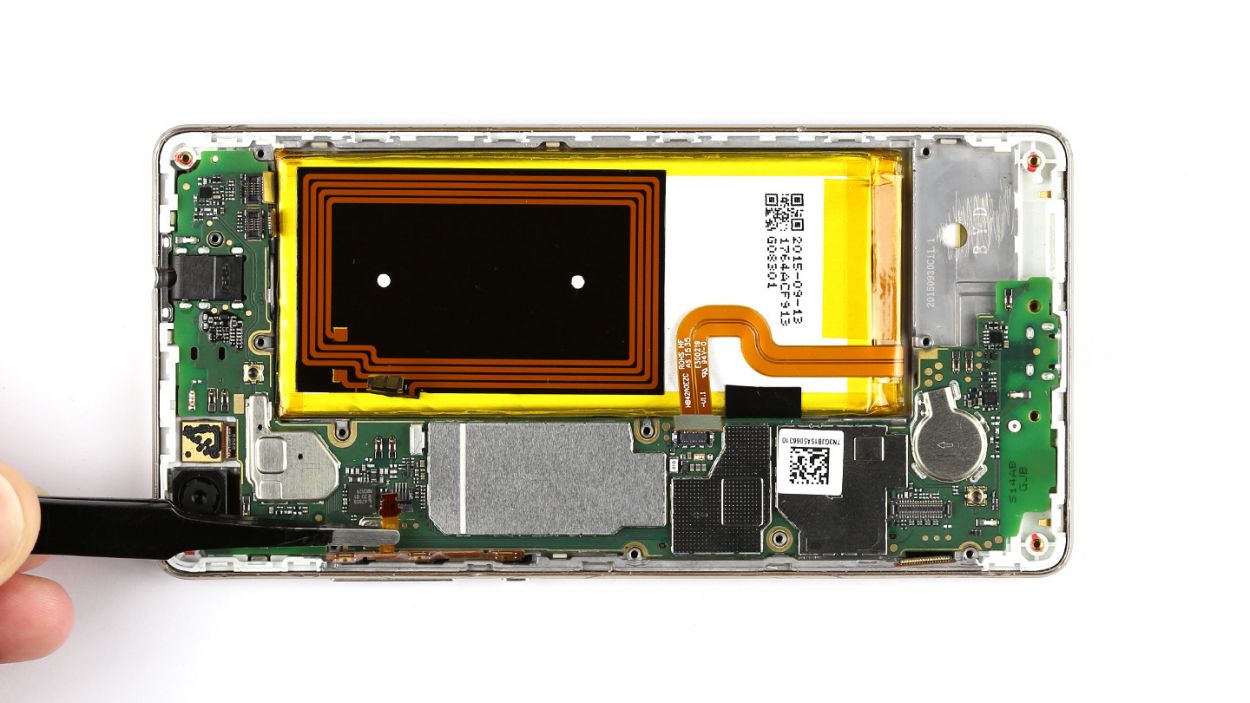
Step 8
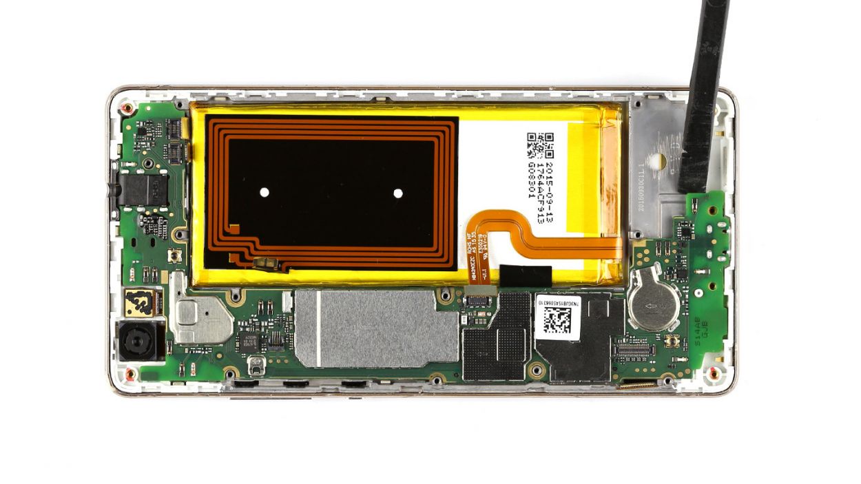
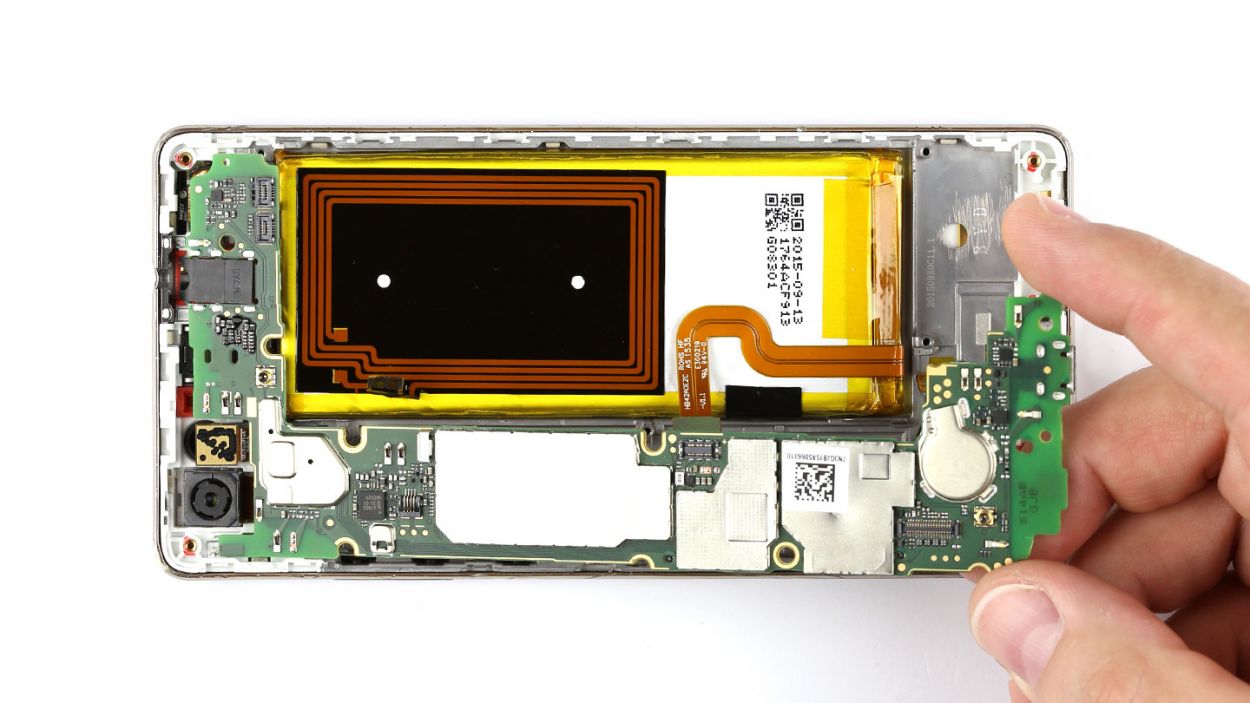
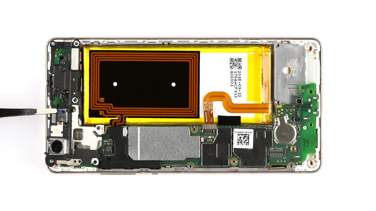
– Gently lift the PCB out of your device. Slide a spudger or a similar tool underneath the board and give it a little nudge upwards.
– With a firm grip, hold the PCB between your thumb and finger, and carefully pull it out.
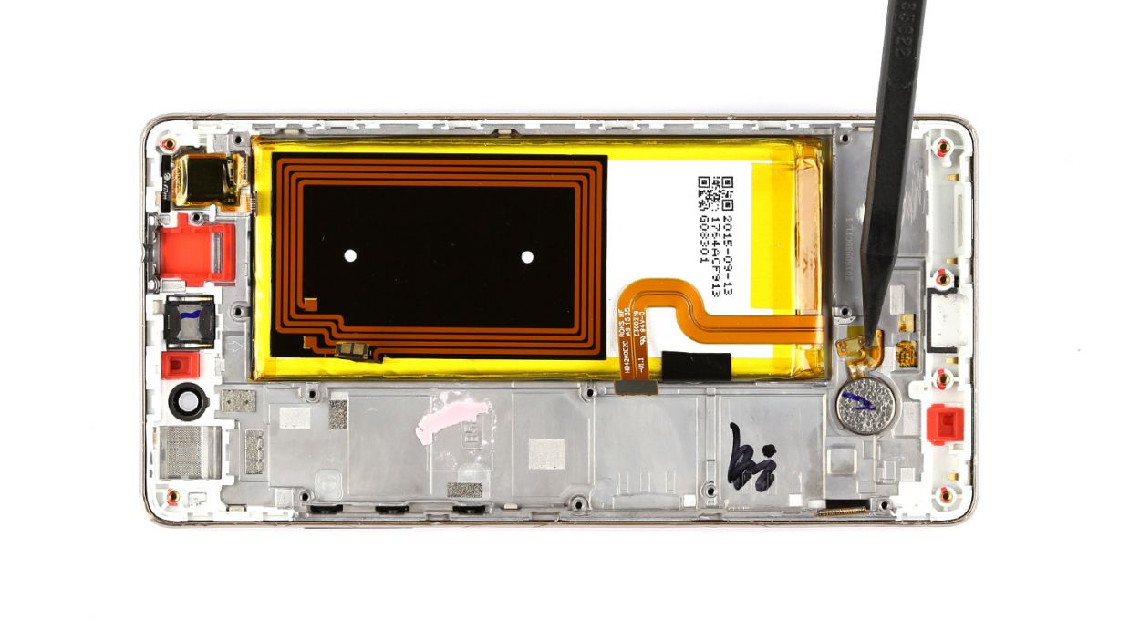
Step 9

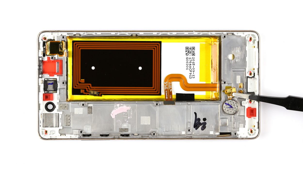
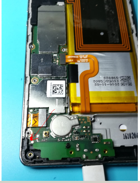
– The vibrator motor is snugly glued to the enclosure. Grab your trusty steel laboratory spatula and gently wiggle it free from its adhesive home.
– Now, go ahead and lift that motor out of your device with care!
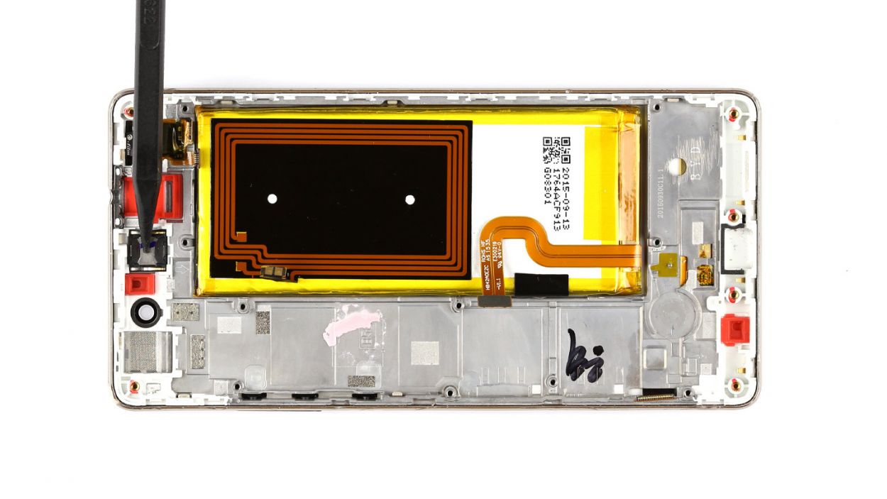
Step 10

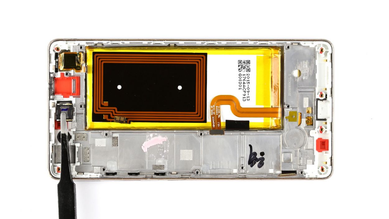
– The earpiece is snugly glued into its cozy little home. Grab your trusty steel spatula and gently pry the earpiece away from the device, then lift it out with care.
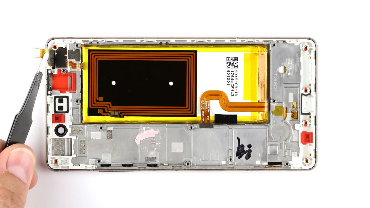
Step 11


– Alright, let’s get those sensors out! First, you’ll find that the two sensors are snugly tucked away in one neat little package under the touchscreen connector. Gently fold back the touchscreen connector to reveal those sneaky sensors waiting to be freed.
– Next up, these sensors are cozy in their recess, firmly glued to the enclosure. Grab a steel laboratory spatula and carefully slide it between the enclosure and the sensors to give them a little nudge and disconnect them.
– Now, it’s time to say goodbye to the sensors. Go ahead and remove them with care!
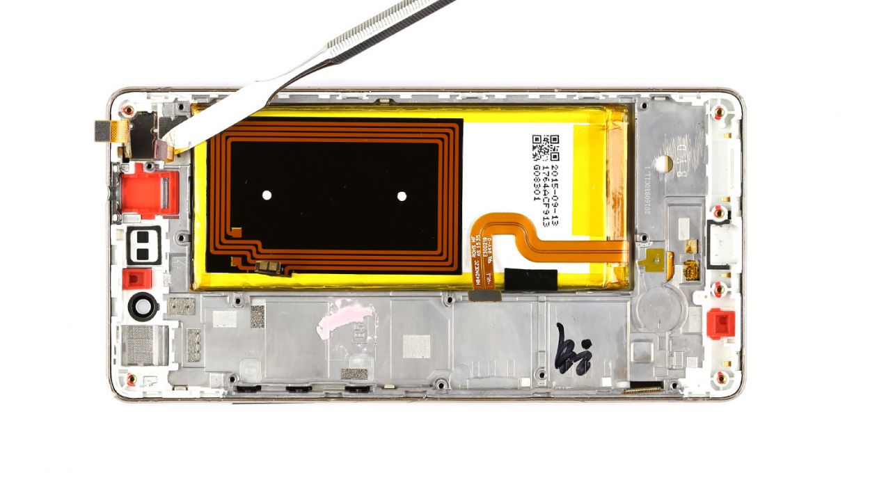
Step 12
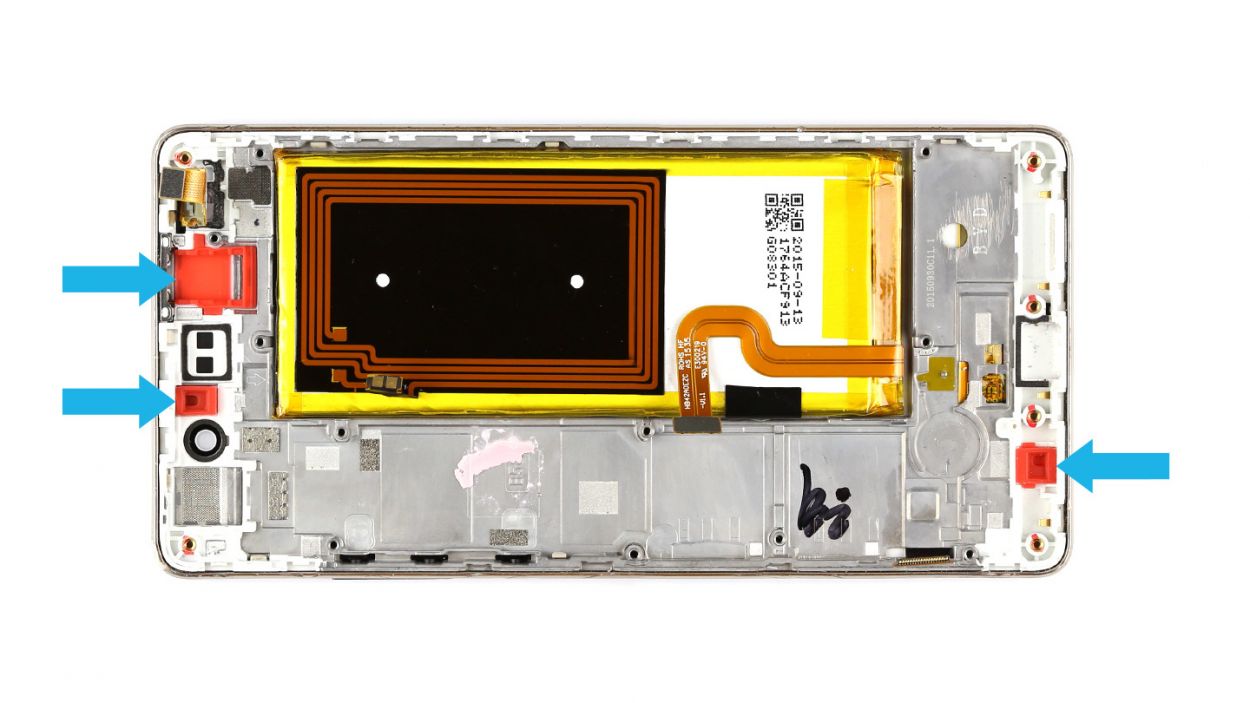
– Not every replacement part is created equal! You might need to swap over a few components, like those three snazzy red rubber sockets for the headphone jack, voice microphone, and ambient microphone. Just think of it as a little DIY treasure hunt!
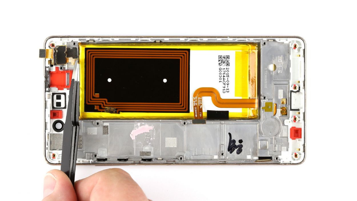
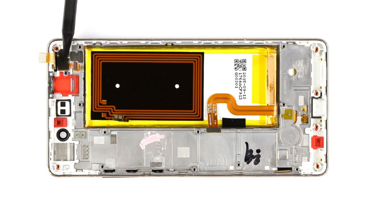
Step 13
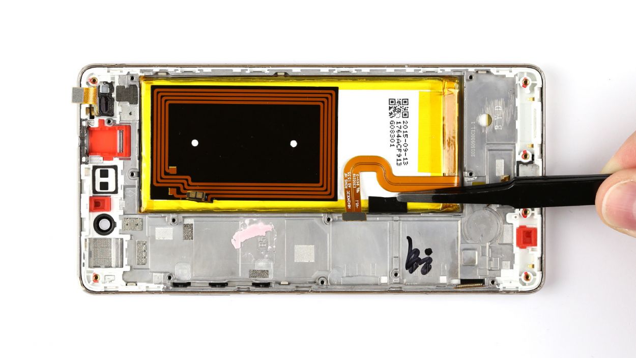
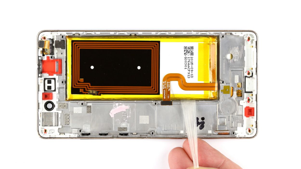
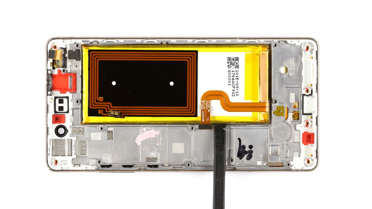
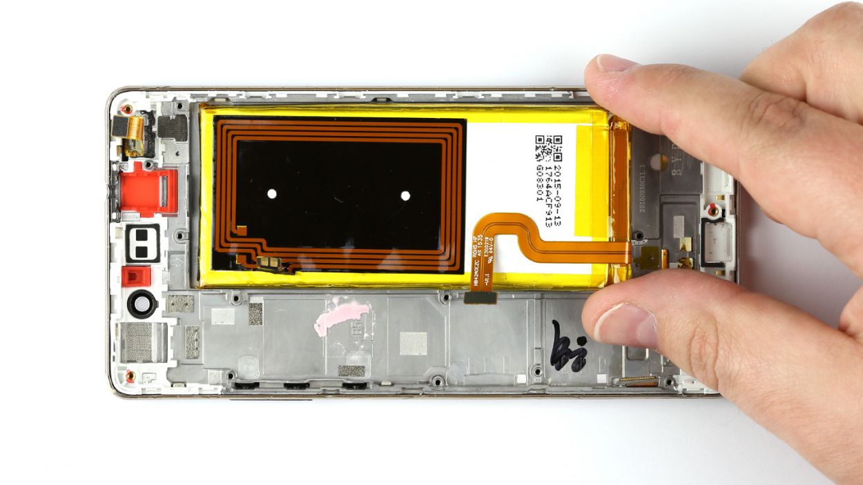
– Uh-oh! It looks like the battery has decided to make itself comfy in the enclosure. No worries! There’s a nifty black tab on the side of the battery just waiting for you to give it a gentle tug.
– Take a deep breath and pull on that tab slowly but surely. It’s got a stretchy adhesive strip that will come along for the ride. Keep going until you’ve freed the entire strip!
– Now, the battery might be feeling a bit too cozy in other spots too. To set it free, you’ll need to carefully pry it away from the enclosure. Just be gentle!
– Once you’ve done that, give yourself a pat on the back and remove the battery from the enclosure. You’re doing great!
Step 14


– Carefully place the battery back where it belongs in the enclosure. You’ve got this!
– If needed, give that tab a little nudge to tuck it into place. Teamwork makes the dream work!
Step 15
– Gently tuck those sensors back into their cozy little home.
– Give them a firm yet gentle push to ensure they’re snug as a bug.
– Now, let’s fold that touchscreen connector back down like a pro!
Step 16

– Carefully place the earpiece back into its cozy little spot and give it a good press to ensure the glue gets a solid grip. You’re doing great!
Step 17

– Gently slide the motor back into its cozy spot in the enclosure. Just make sure those two studs find their way through the connection cable’s two little holes.
– Give the motor a firm press to help it stick like a champ once more.
Step 18

– Gently place the PCB into the enclosure, ensuring it’s snugly in the right spot. Start by inserting the upper end of the PCB first, allowing you to easily slide the headphone jack through the opening in the frame. You’ve got this!
Step 19


– Pop those control buttons back in and connect them to the motherboard like a pro!
– Gently slide that cable back into its cozy socket and secure it with the bracket.
– Carefully press the connector into the socket to link up the sensors with the board.
– Repeat the same process for the touchscreen connector, and you’re on your way!
Step 20


– First things first, flip that smaller cover upside down and place it on the battery. Time to reconnect that NFC antenna contact!
– Next, pop the antenna contact back into its cozy spot on the cover. Give it a good press to make sure they bond nicely.
– Now, carefully position the cover back onto the motherboard. It’s all about that perfect fit!
– Alright, let’s bring the larger cover back into the mix. Ensure that the little cover and the big cover are snugly hooked together.
– Finally, grab those seven screws and secure the covers to the enclosure. You’ll need 5 x 2.7 mm PH00 Phillips screws and 2 x 3.7 mm T5 Torx screws. You’ve got this!


Step 22

– Carefully place the speaker back into the lower section of your device.
– Secure the speaker in place using the seven screws: three 2.7 mm PH00 Phillips screws and four 3.7 mm T5 Torx screws. You’ve got this!
Step 23


– Put the back cover back on.
– Use your finger to press it onto the entire frame so all the clips on the back cover click into place on the enclosure.
Step 24
– Carefully pop the SIM and microSD cards back into their respective trays and slide those trays back into your device.
– Give them a gentle push until they’re snug and flush with the enclosure.