DIY Guide to Replace Huawei P9 Lite Screen
Duration: 45 min.
Steps: 30 Steps
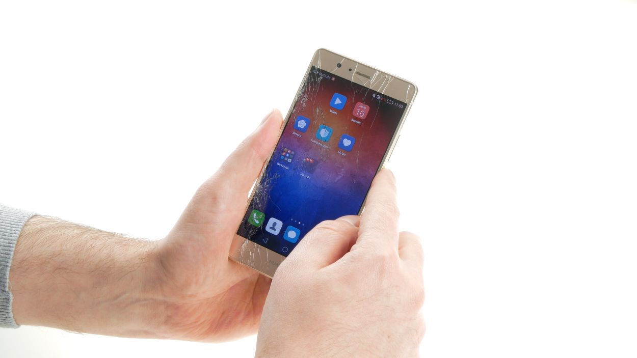
Ready to bring your P9 lite back to life? This guide will help you tackle a faulty display, whether it’s got a cracked glass, isn’t responding to your touch, or the LCD is playing hide and seek with a black or flickering screen. Before diving in, make sure to back up all your precious data and give a little touch to something metal, like a radiator, to zap away any pesky static charges. Let’s get started!
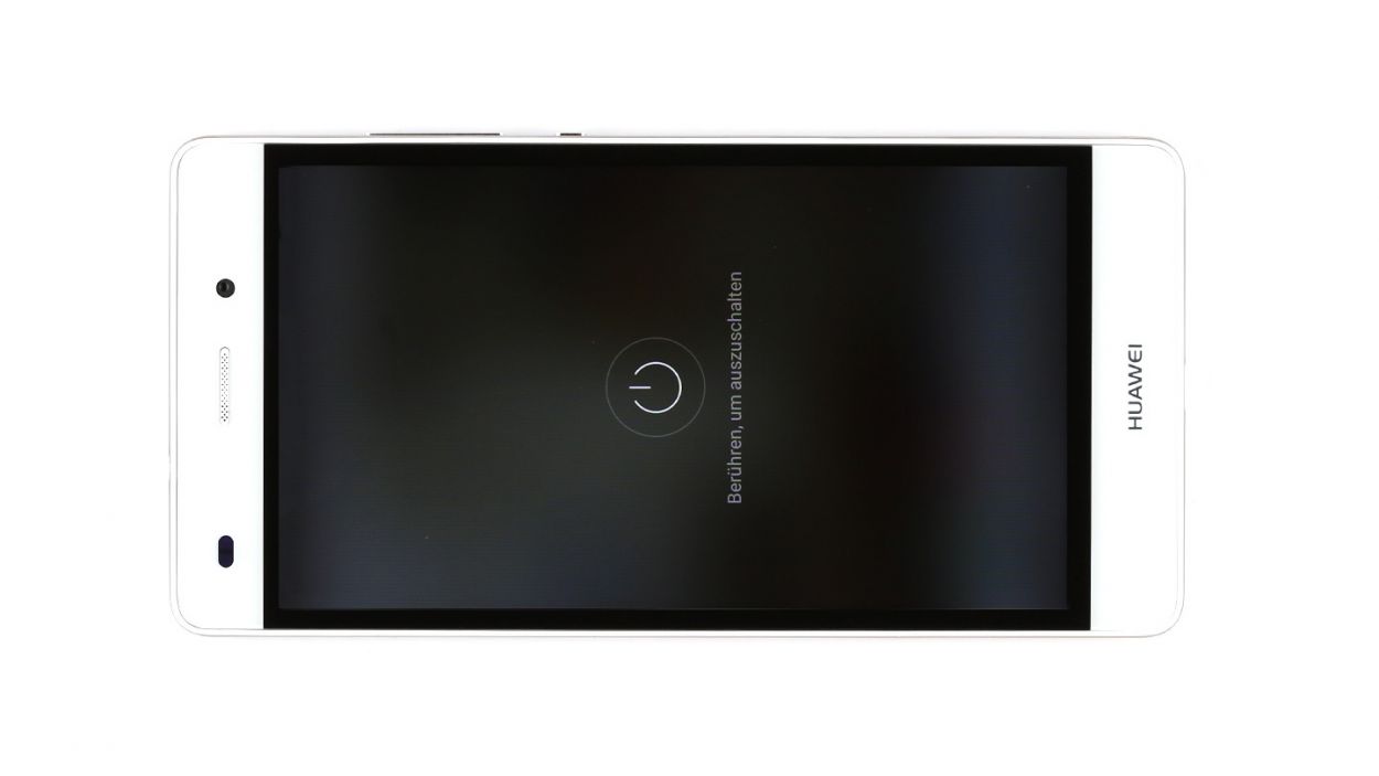
Step 1
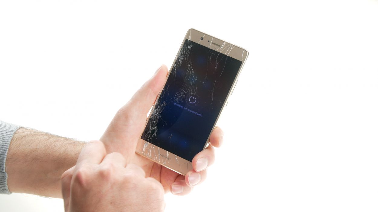
– Give that standby button a good press and hold until the shutdown dialog pops up on your screen.
– Go ahead and tap to confirm your choice.
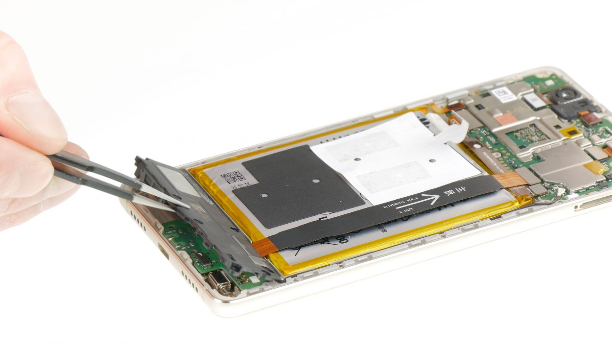
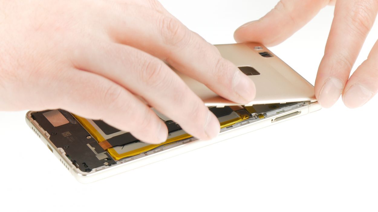
Step 2
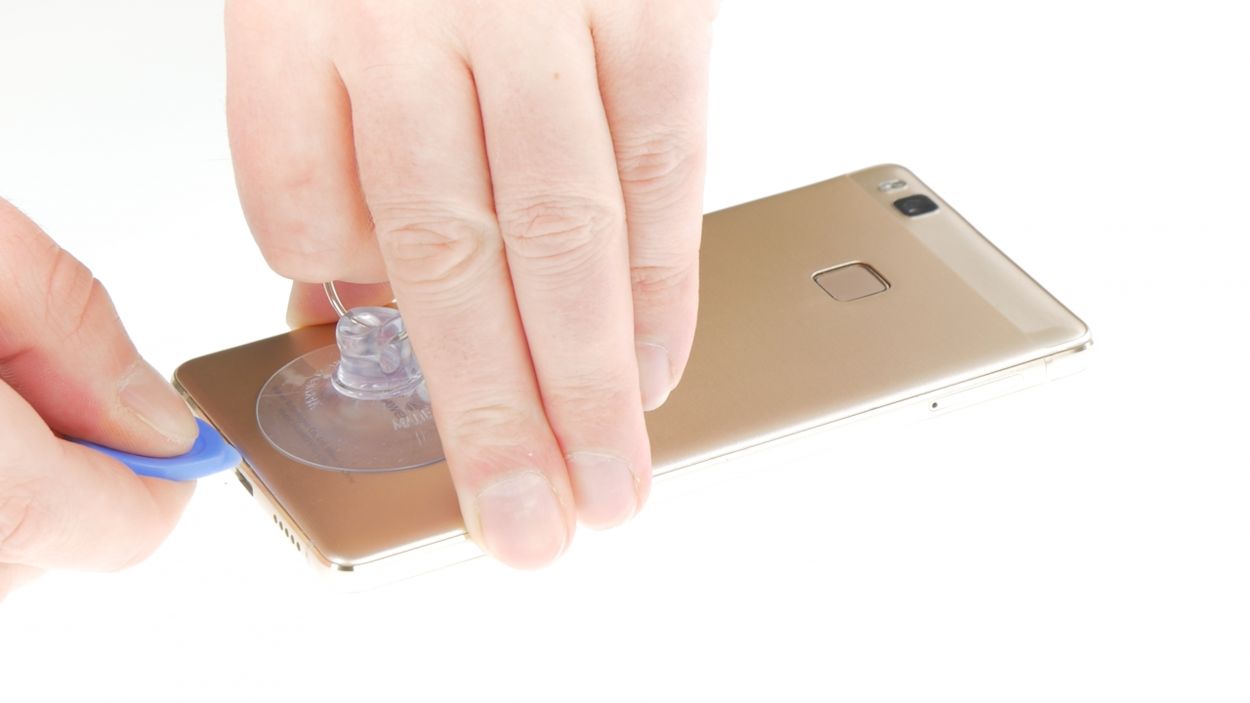
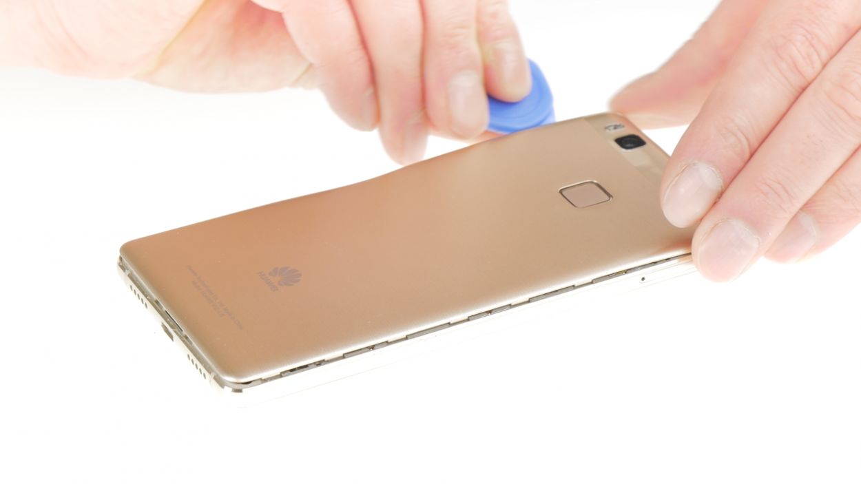
– Grab that suction cup and place it a bit lower on the back cover. Give it a gentle pull to lift that cover right off!
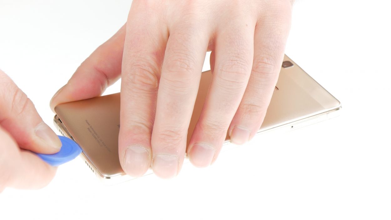
– Next, slide your pick between the display unit and the back cover, and give it a little pry to separate them.
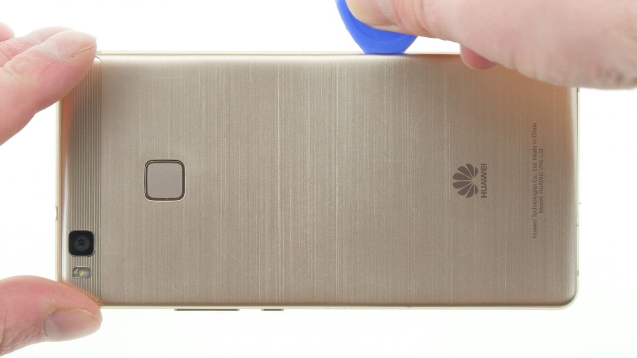
– Don’t forget to release the back cover clips all around the device. If it doesn’t pop off on the first try, no worries! You can always use a second pick or give it a firmer tug with your fingers.
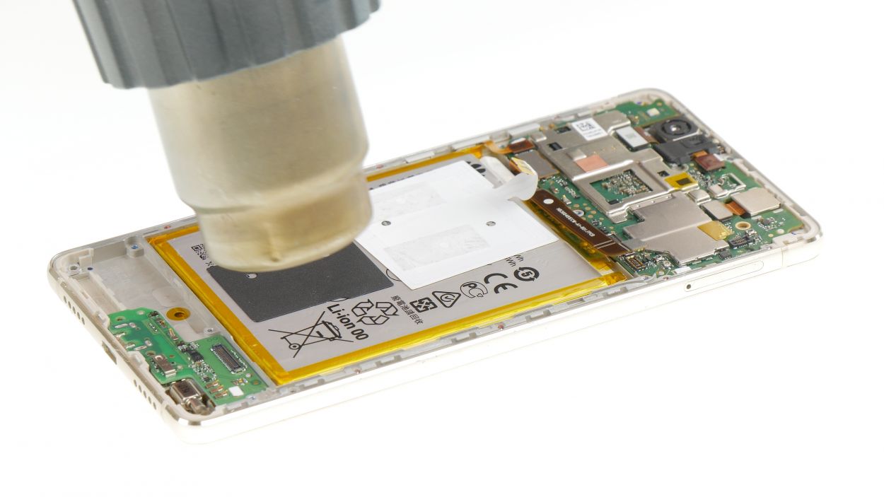
– Just a heads-up: the back cover is glued to the fingerprint sensor. A little heat from a heat gun can help loosen that glue, making it easier to remove.
– Once all the clips are free, you can easily take off the back cover and carry on with your repair adventure!
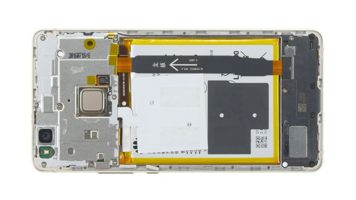
Step 3

– First things first, those pesky Phillips screws are holding the cover tight. Unscrew them all and keep them in a safe spot, so they don’t go on an adventure without you!
– Now, give the cover a little lift. Just a bit, like you’re teasing it to come out.
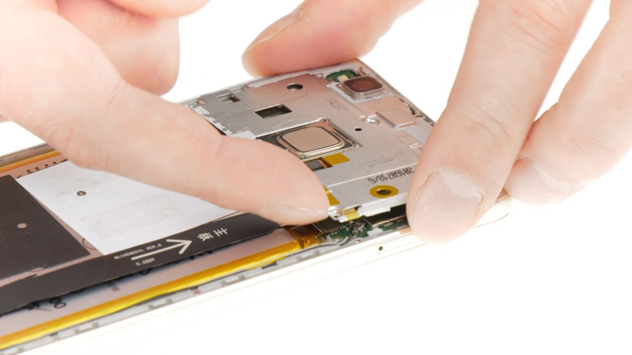
– The cover is clipped in, once near the camera and once on the side. Gently wiggle the cover to unclip it, and then swing it open like a door to a secret room.
– Grab a spudger and carefully pry off the connector for the fingerprint sensor flex cable. It’s a delicate dance, so be gentle!
– Next up, let’s tackle the NFC antenna. It’s glued down, but if it’s being stubborn, warm it up a bit with a heat gun, then use a spatula to coax it off. You’re doing great!
9 × Phillips
Fingerprint sensor
NFC connector
Heads up! There are quite a few cables hanging out beneath. Tread carefully!
There’s a little humidity indicator hanging out near one of the screws. You might be tempted to take it off and put it back later, but let’s be real—it often doesn’t survive the journey. So, why not just give it a gentle poke with a screwdriver instead? Easy peasy!
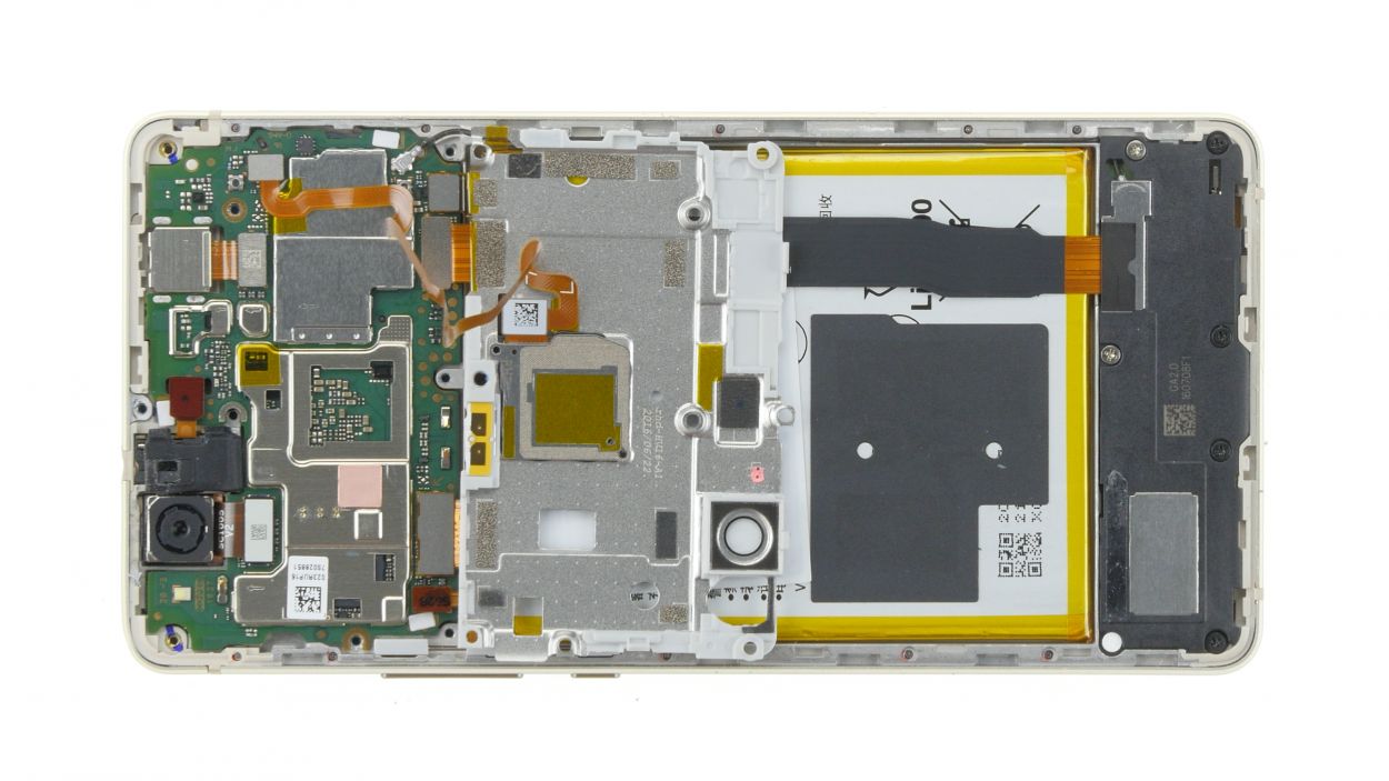
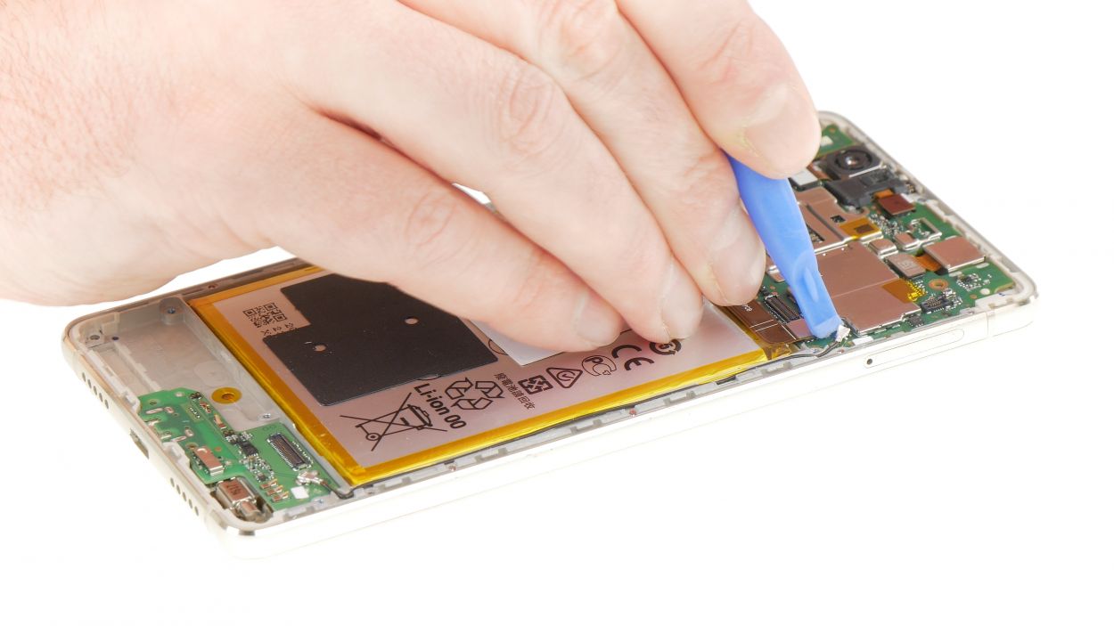
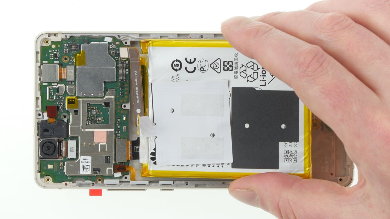
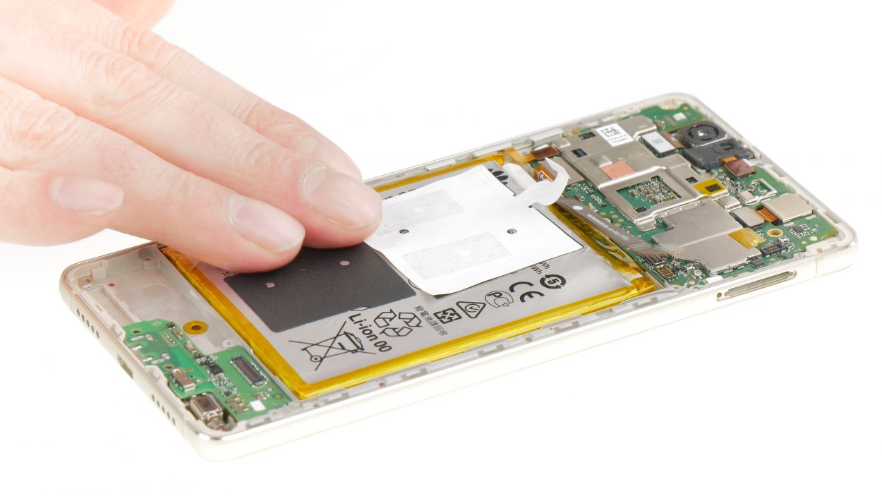
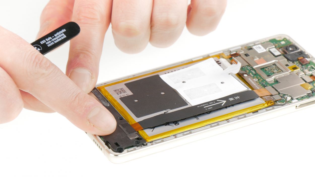
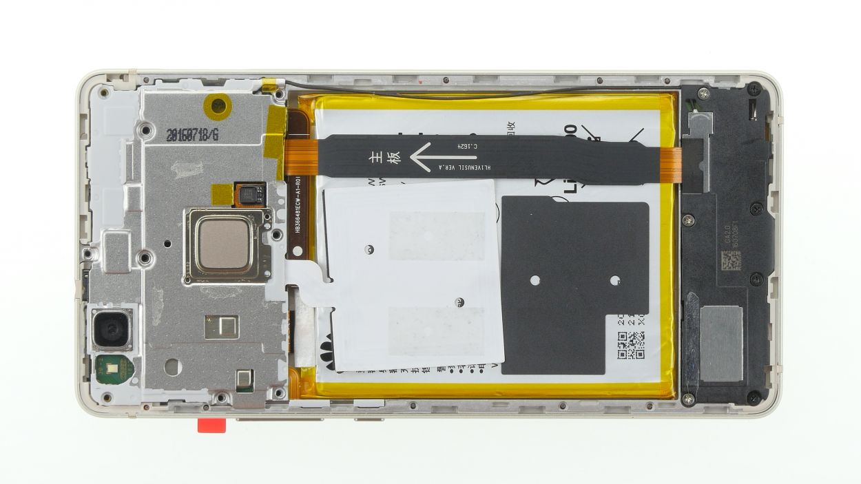
Step 4

Battery connector
– Use a spudger to carefully pry off the connector of the battery flex cable.
Step 5
3 × 2.9 mm Phillips
4 × 3.8 mm Phillips
Heads up! You’ve got screws of two different lengths here. Keep them in separate spots so you can pop them back in just right later on!
– First things first, let’s tackle those pesky Phillips screws holding the plastic cover in place. Get them out of there!
– Next up, it’s time to gently coax the speaker and its cover out. Grab a thin tool and slide it into the little opening at the bottom edge of the device. Give it a gentle pry, and voila, the speaker should pop right out!
– Now that you’ve got the speaker freed, you can take it out and move on to the next step!
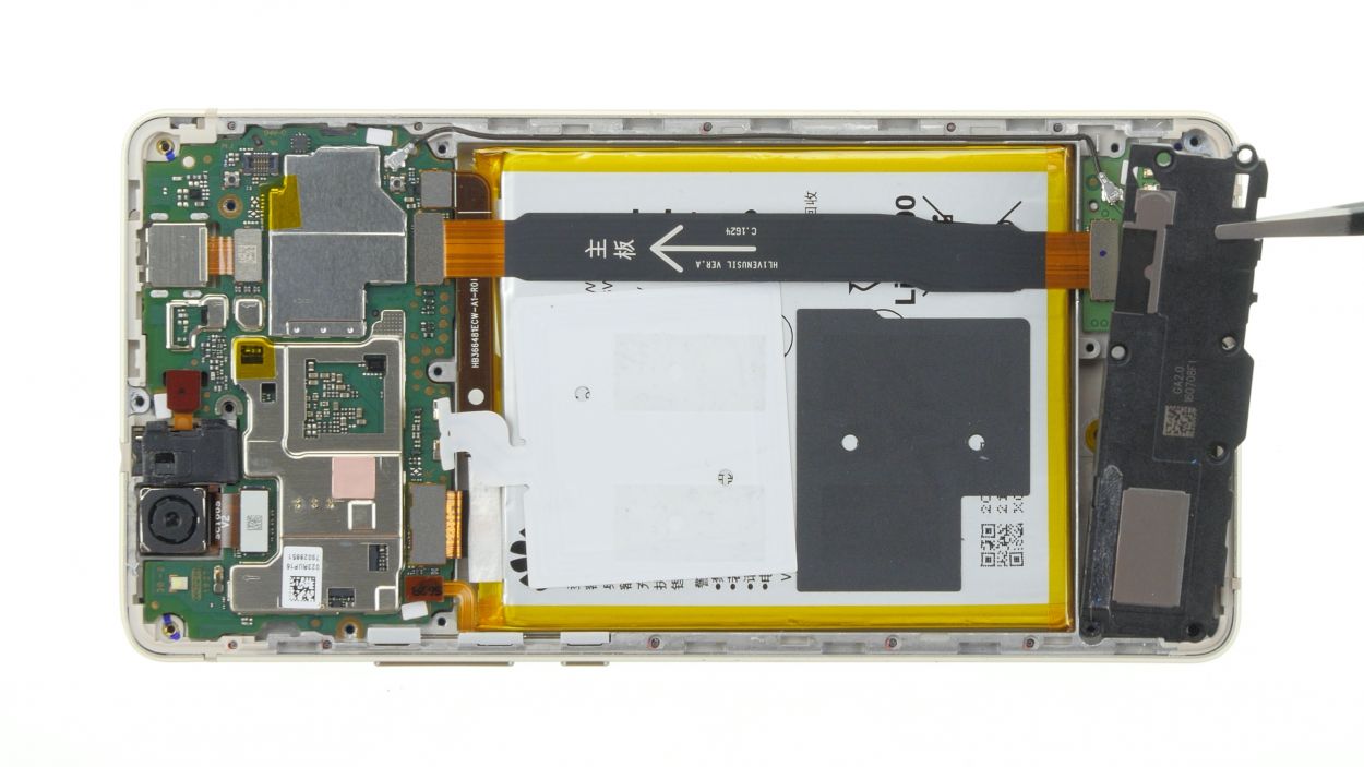
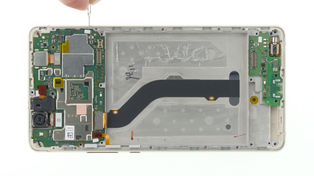
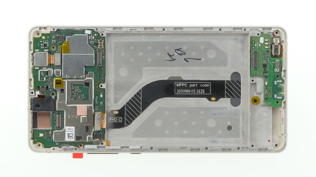
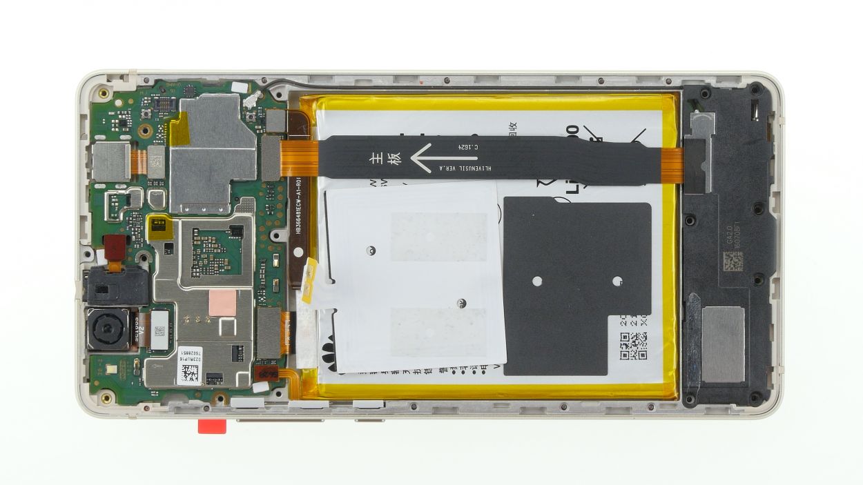
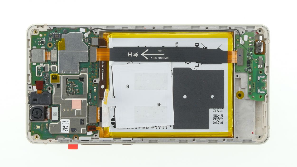
Step 6
Flex cable connector
2 × Antenna plug
Pry with care, or you might accidentally pop those sockets right off the PCBs!
No need to stress about the black antenna! It can stay put while you swap out the battery. You’ve got this!
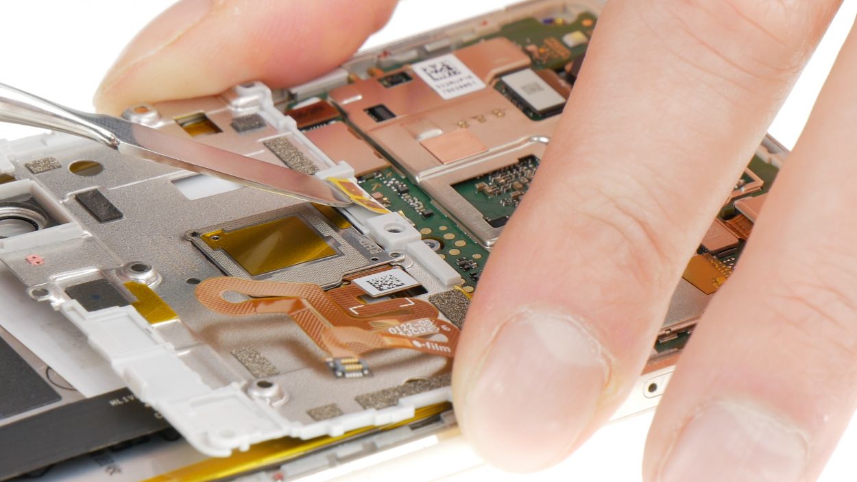
– Grab your trusty spudger and gently nudge those plugs off both sides of the antenna cable. You’ve got this!
– Next, let’s say goodbye to the antenna cable. Off it goes!
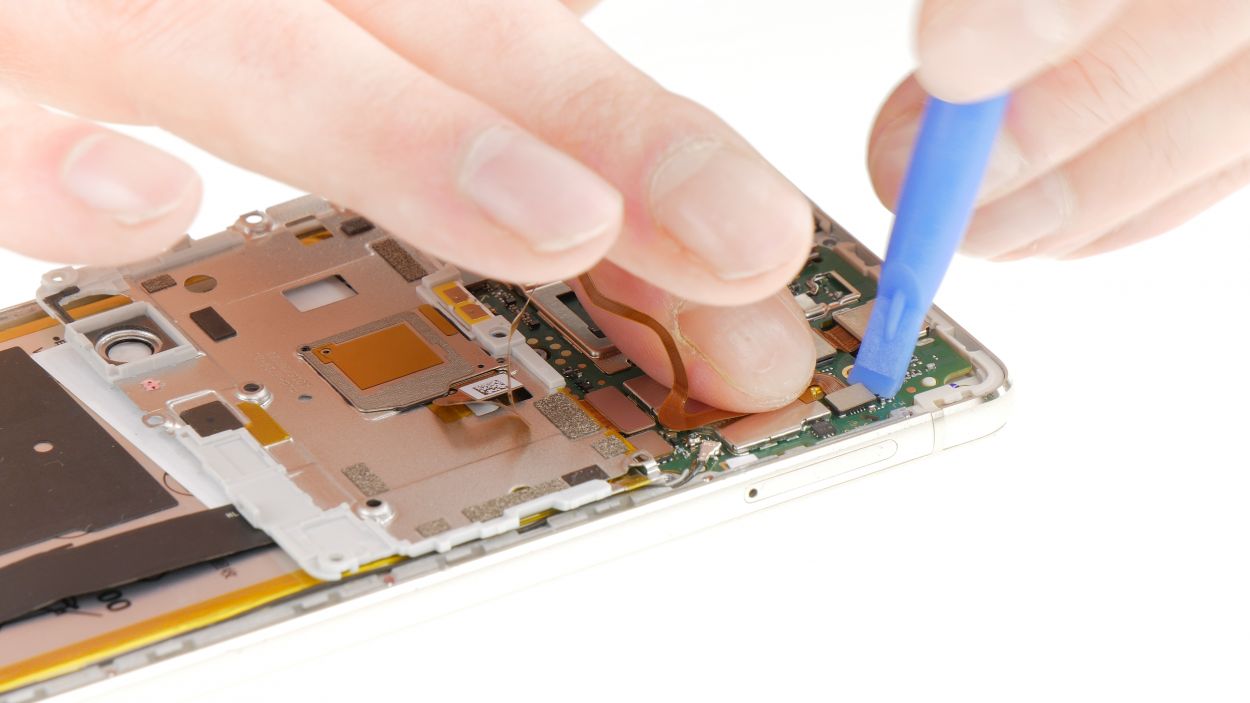
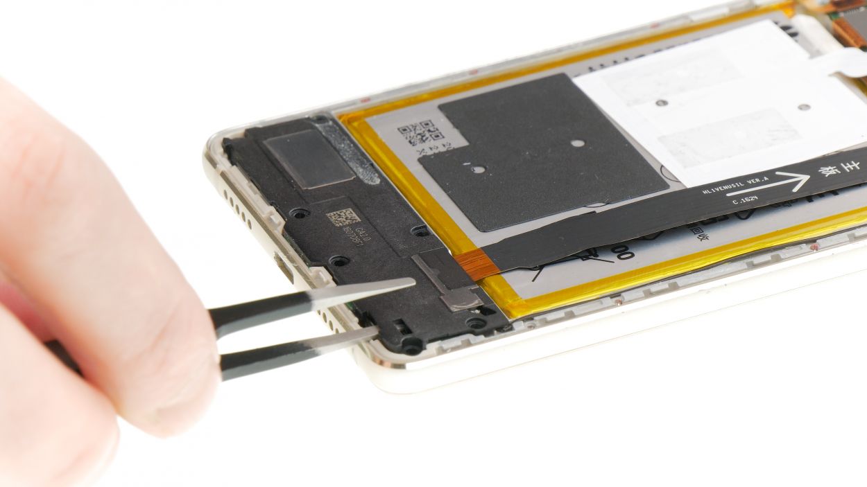
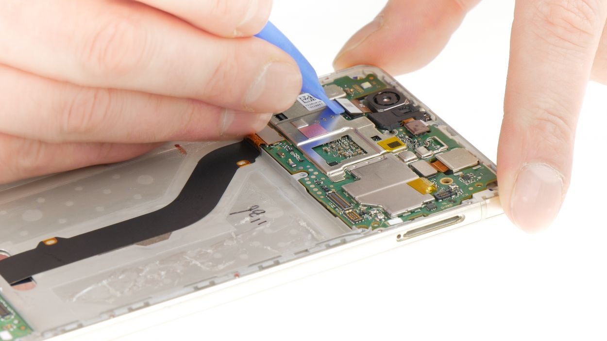
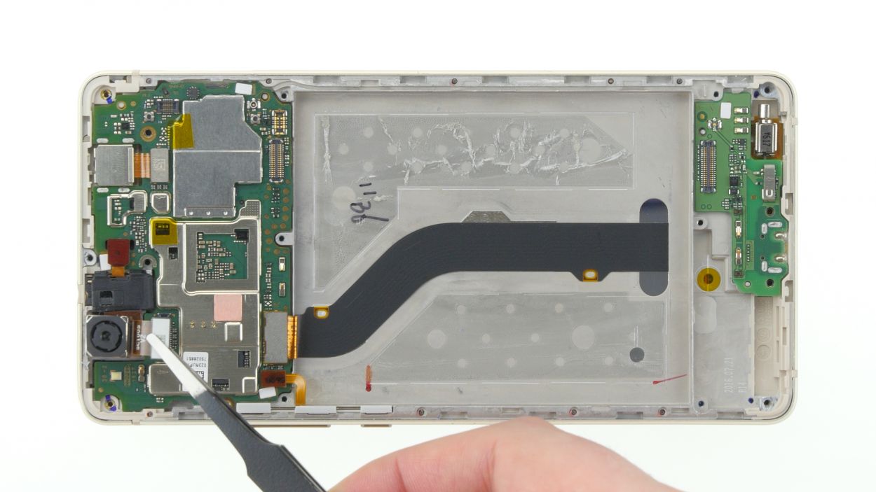
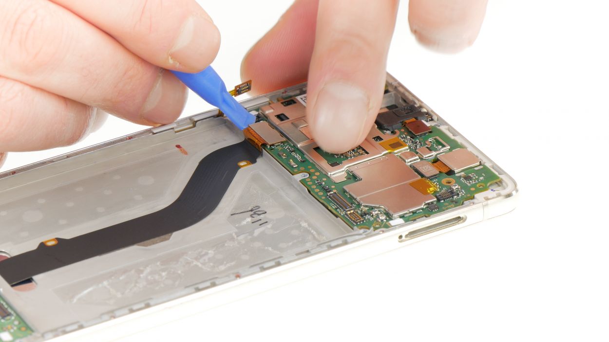
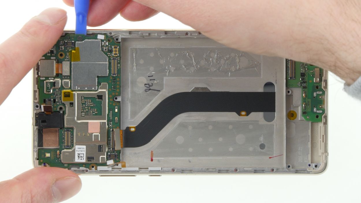
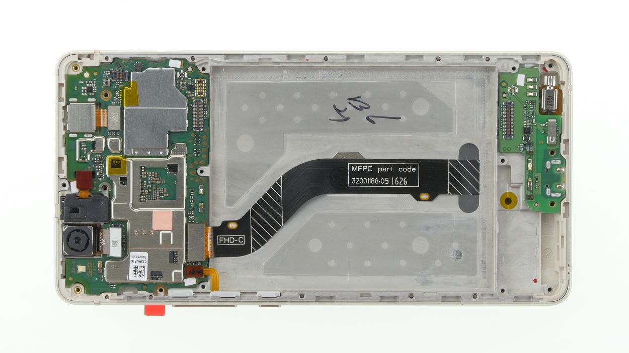
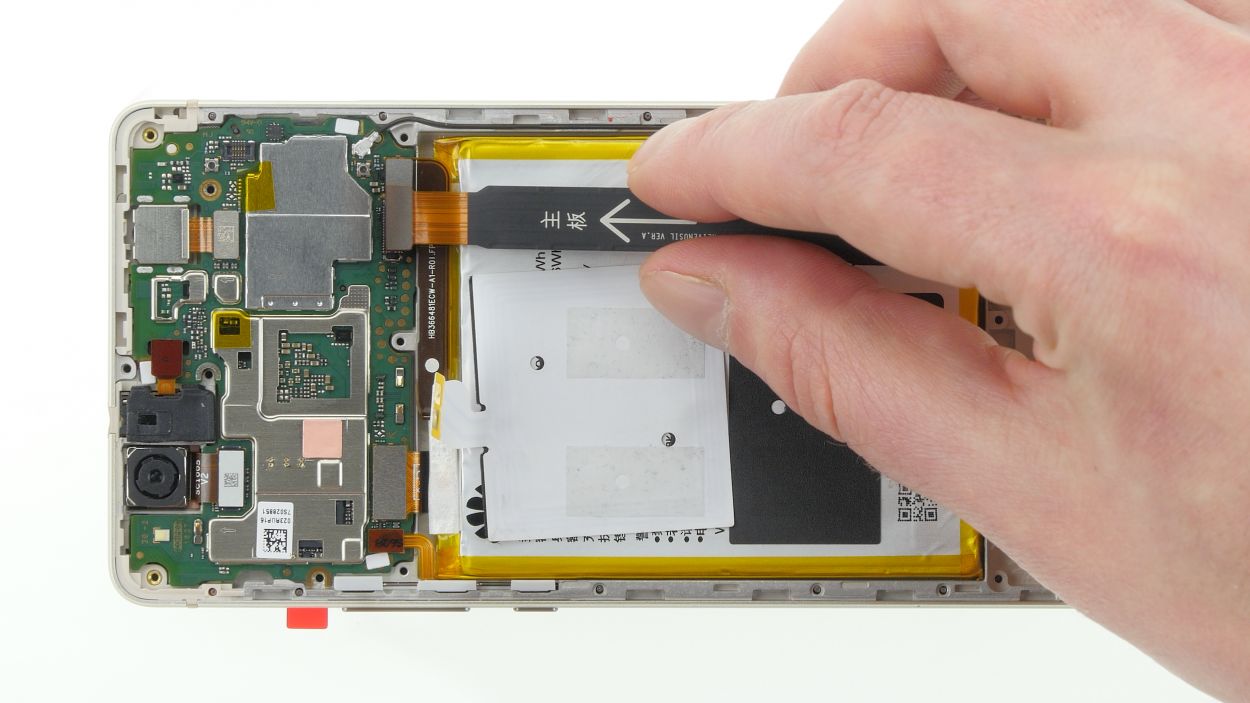
– Now, use that spudger again to delicately pry off the connectors on both sides of the large flex cable, just like the arrow shows. Easy peasy!
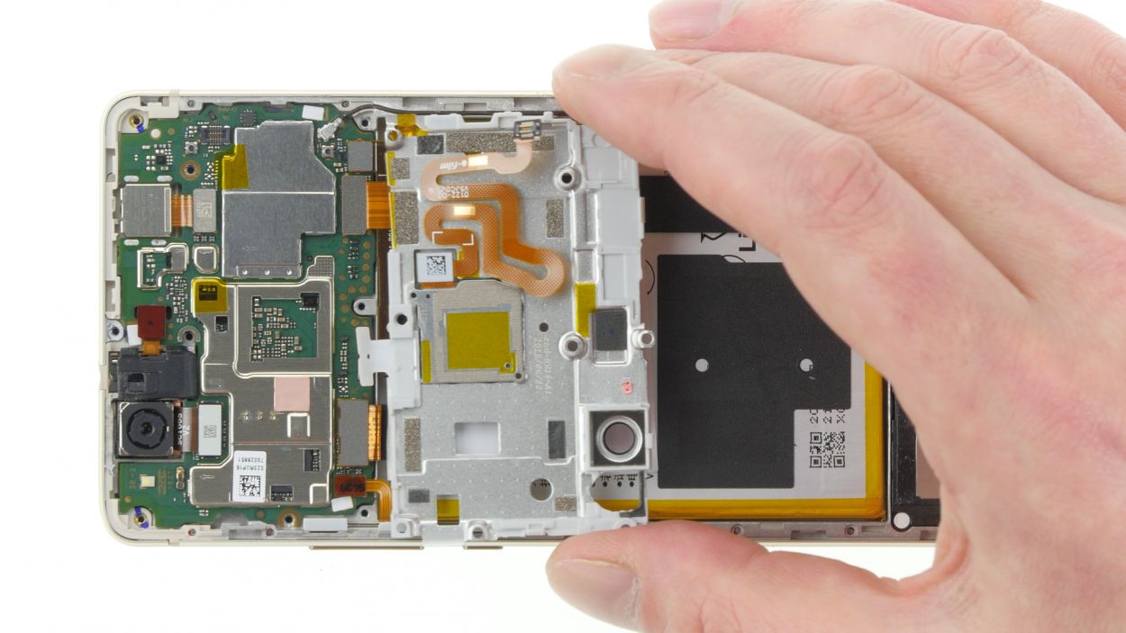
– Finally, remove the flex cable and give yourself a pat on the back for a job well done!
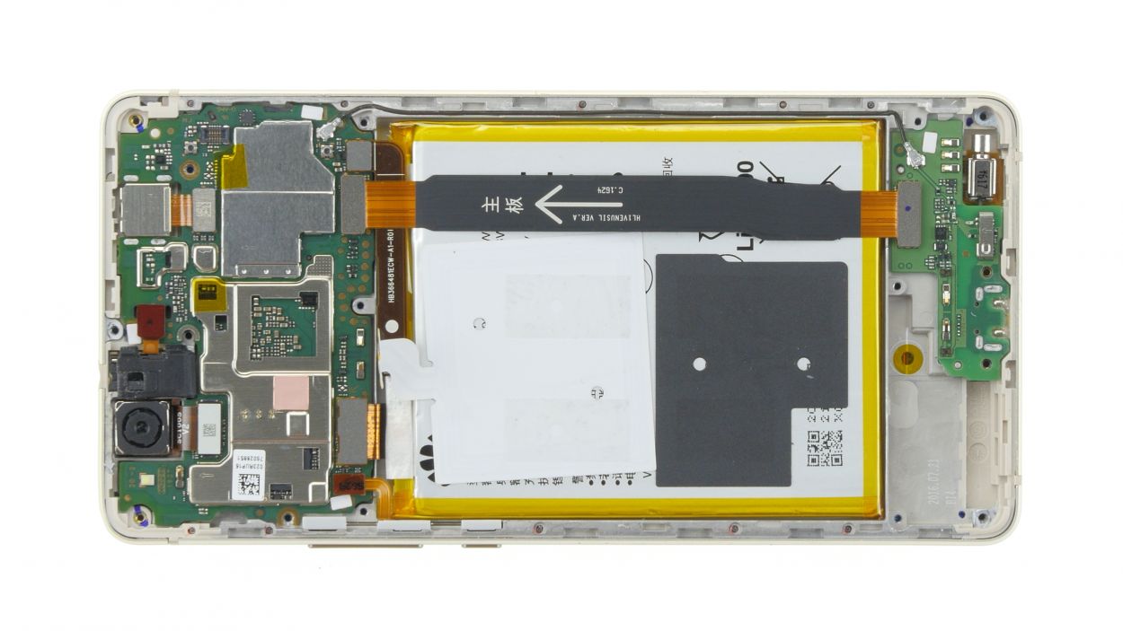
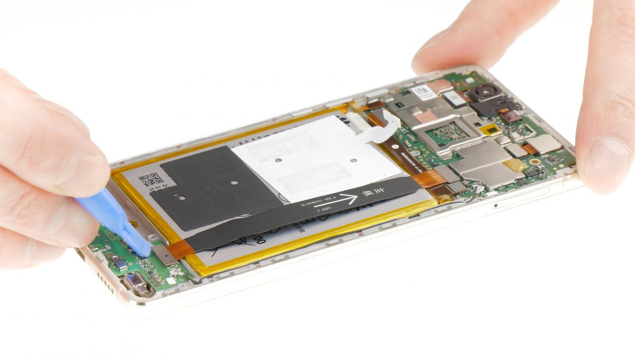
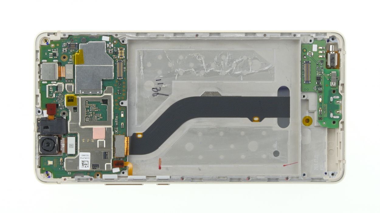
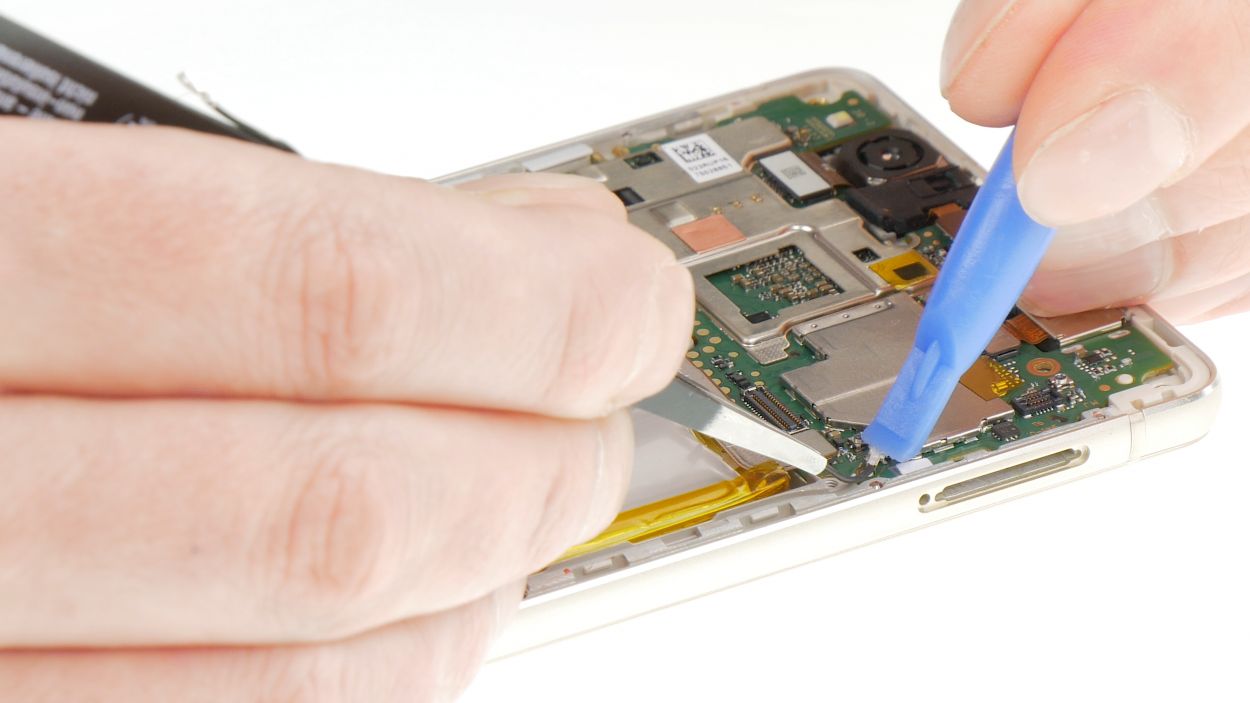
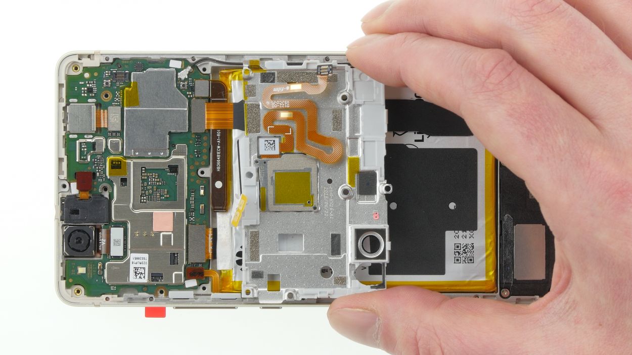
Step 7

Step 8
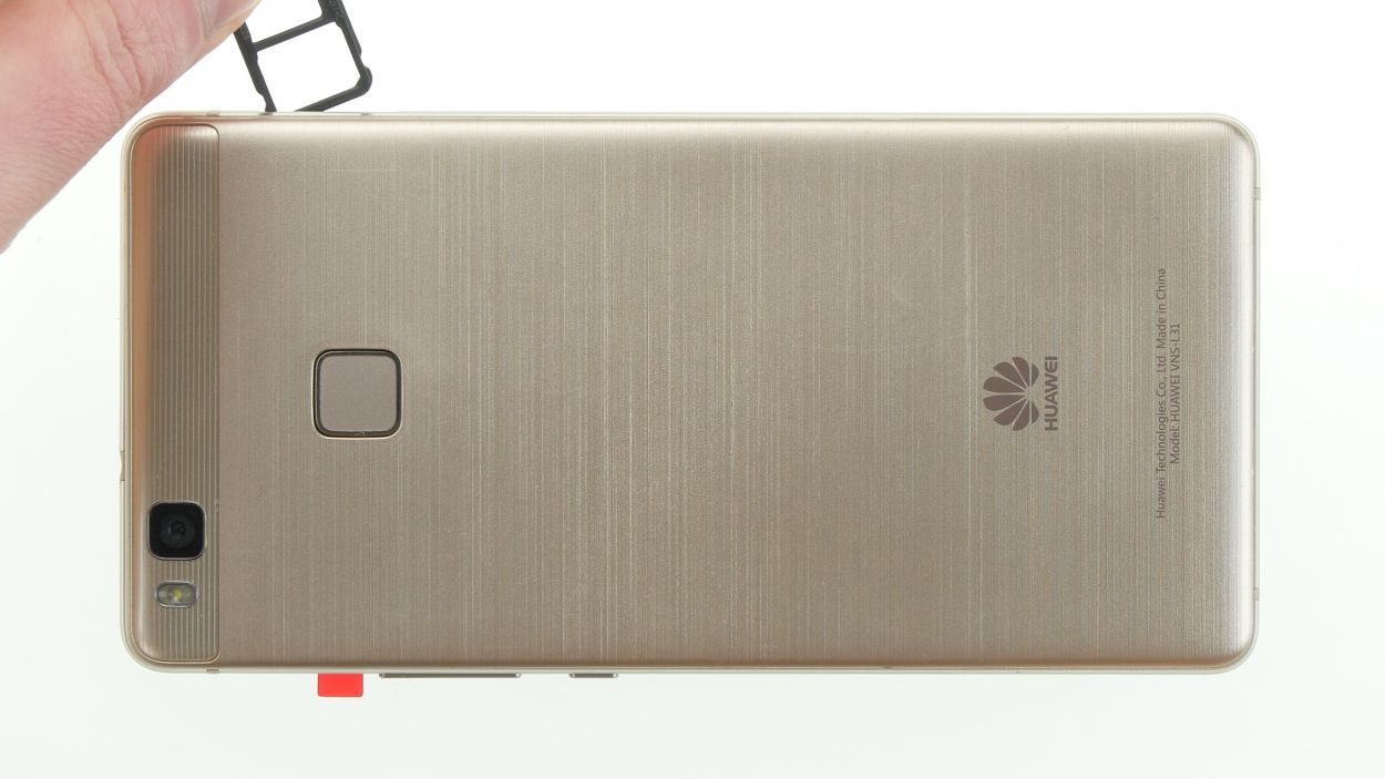
– Hey there! Let’s pop open that SIM tray. Grab your SIM tool and gently insert it into the tiny hole – you’ll see it! – to unlock the tray.
– Sweet! Now, slide out the tray and give those SIM and microSD cards a little wave goodbye (for now!).
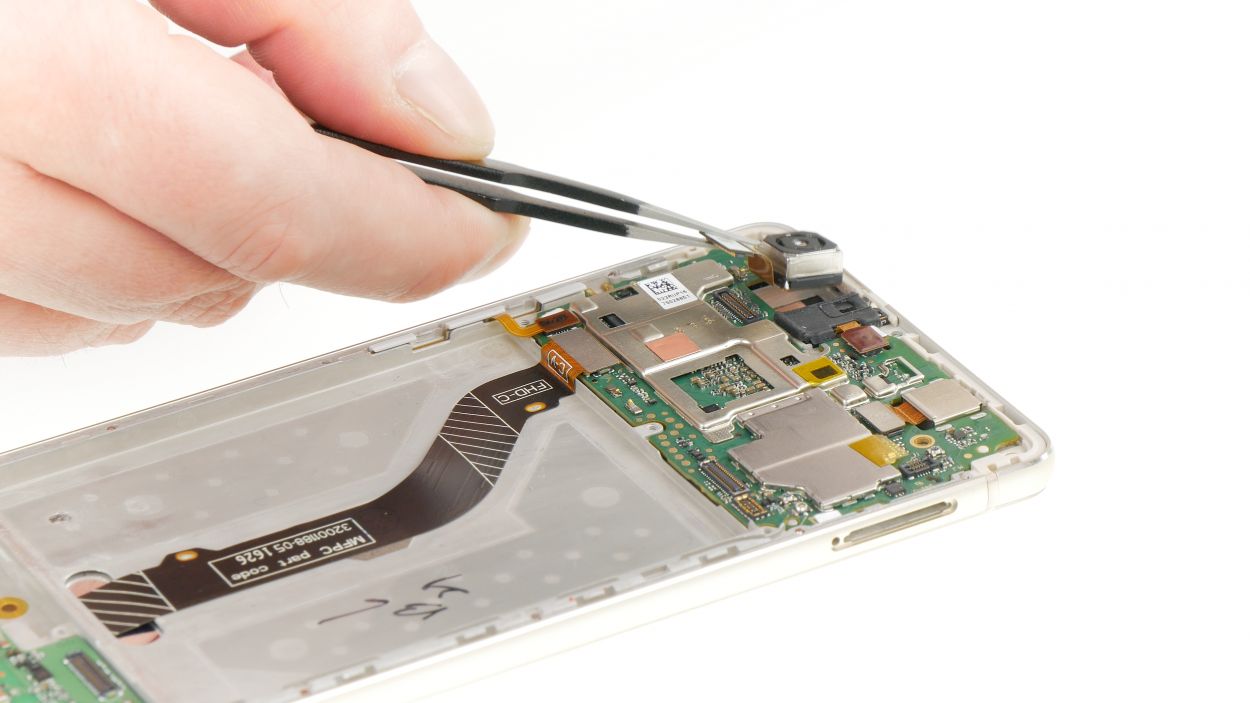
Step 9
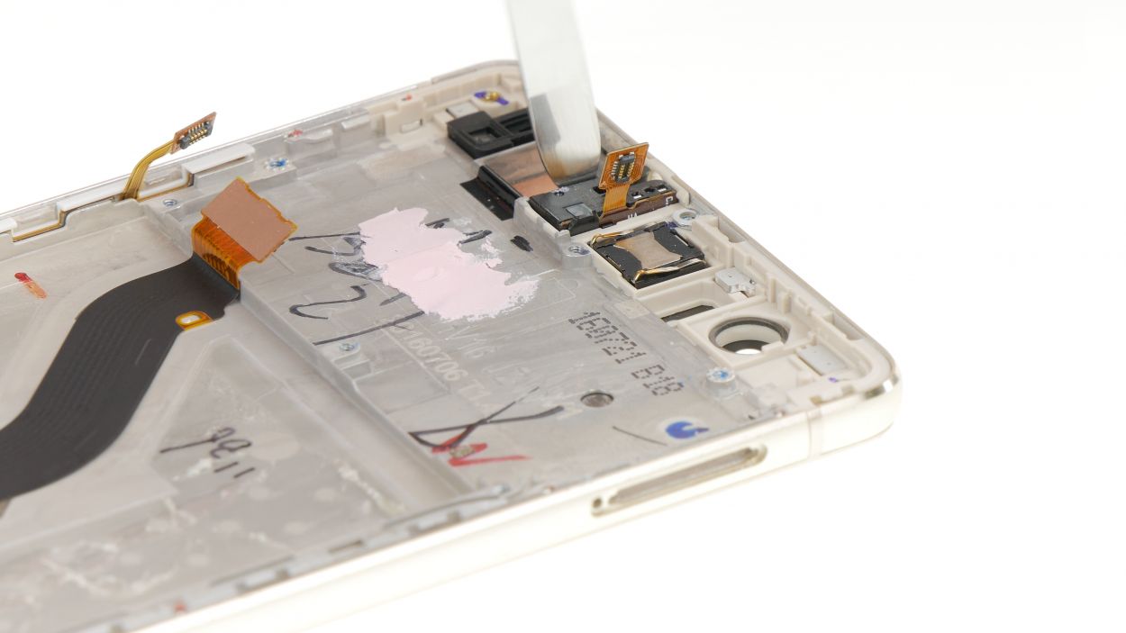
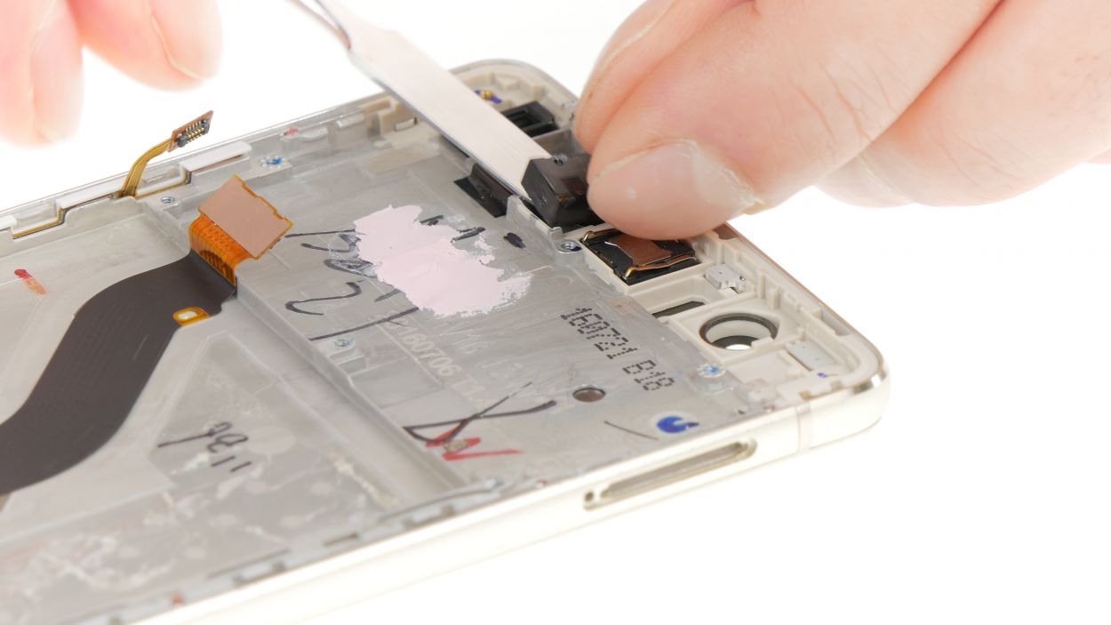
– Let’s gently pop off that rear camera connector using a spudger. Piece of cake!
– Now, it’s time to give that front camera a little nudge and remove it from the display. You got this!
Step 11
– First, let’s get that rubber gasket off! It’s got a bit of glue holding it down, but with a gentle tug, it should come right off.
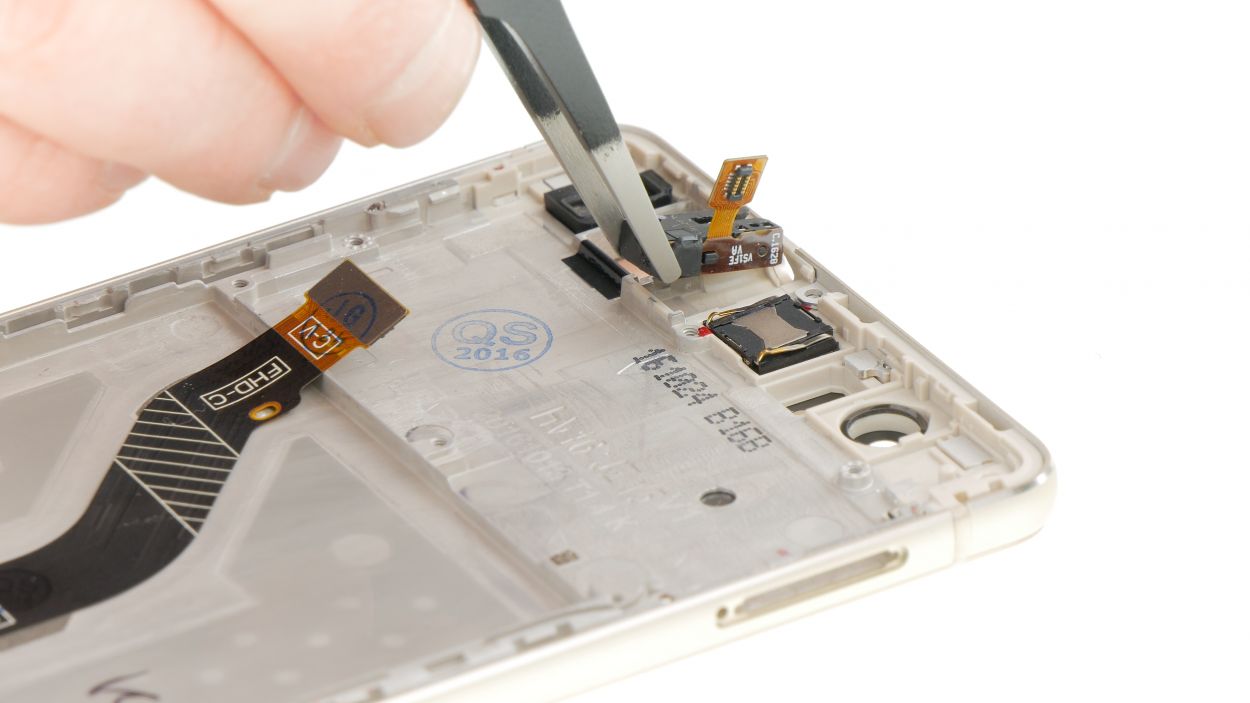
– Now, it’s time to carefully pop out the audio port and detach it from the display unit. You’ve got this!
Step 12
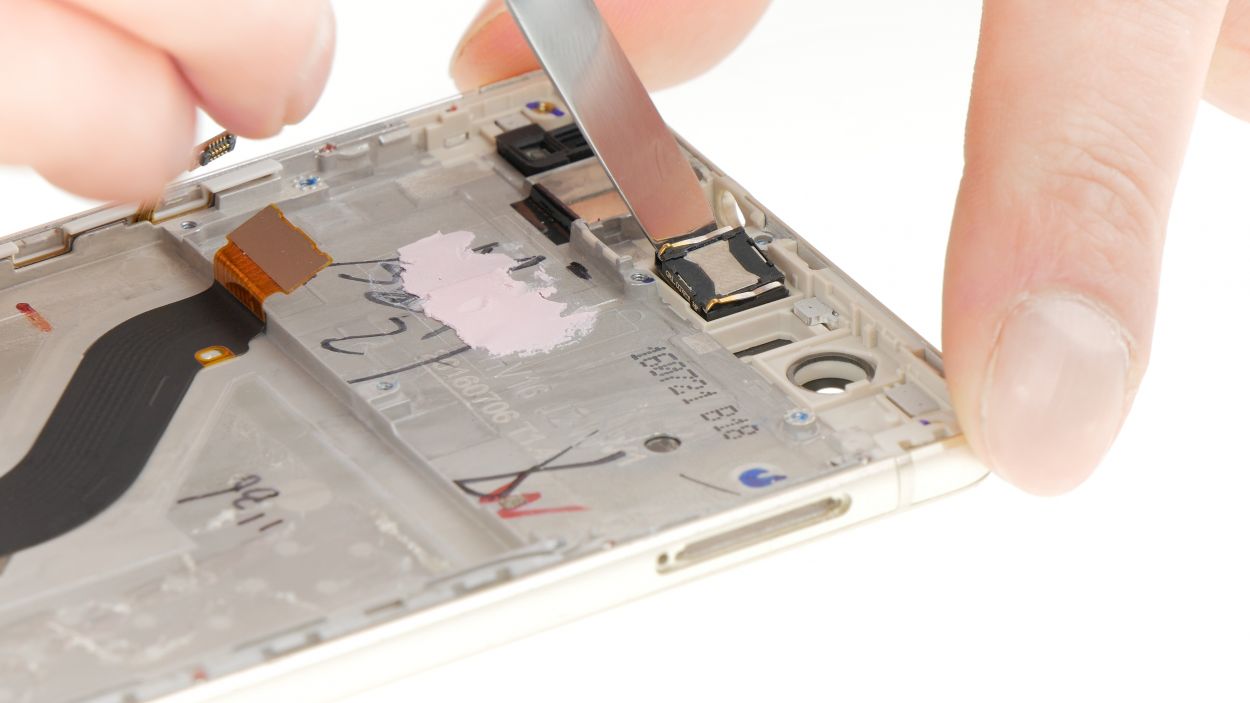
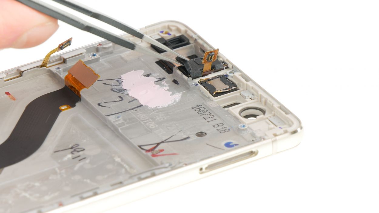
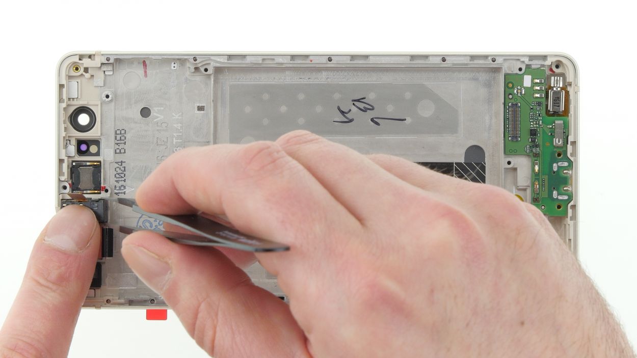
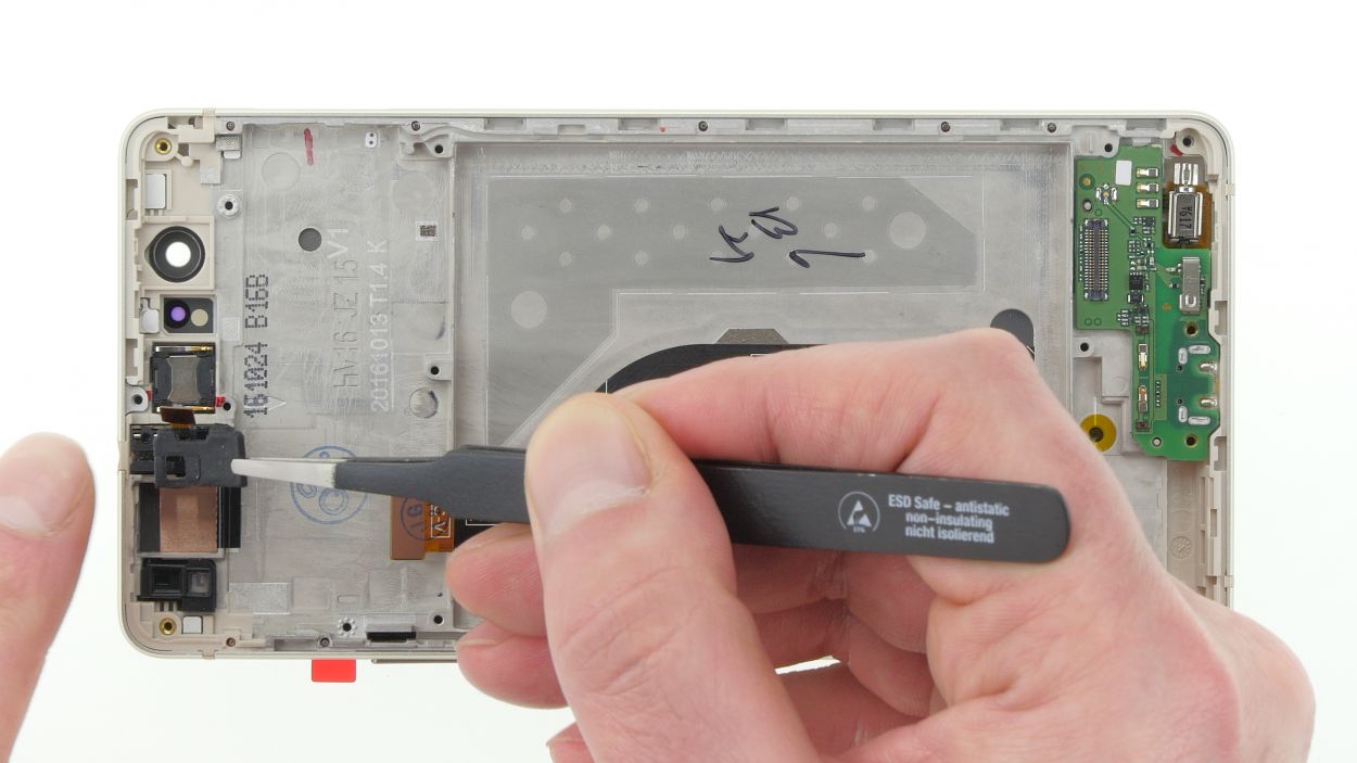
– Gently pop out the earpiece. It’s got a little glue holding it in place, but it should come off without much fuss.
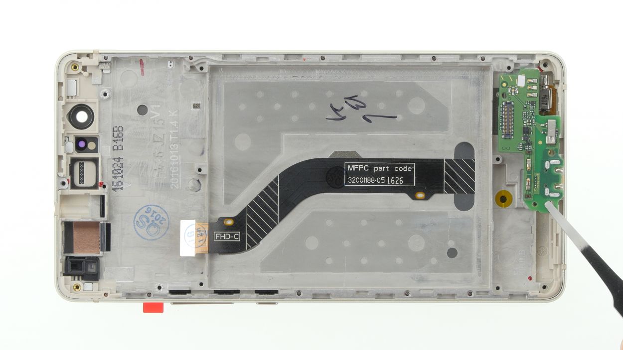
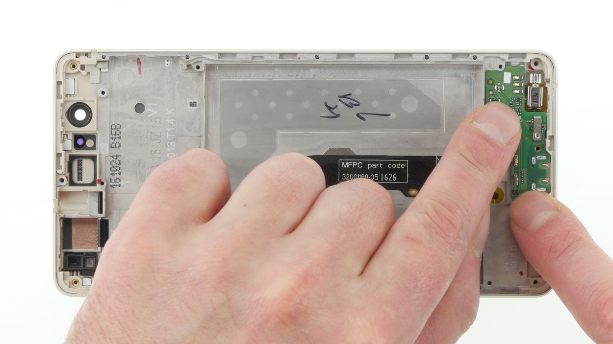
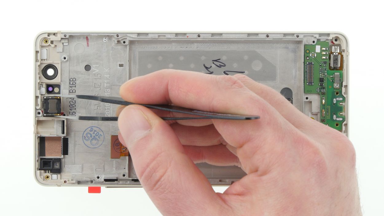
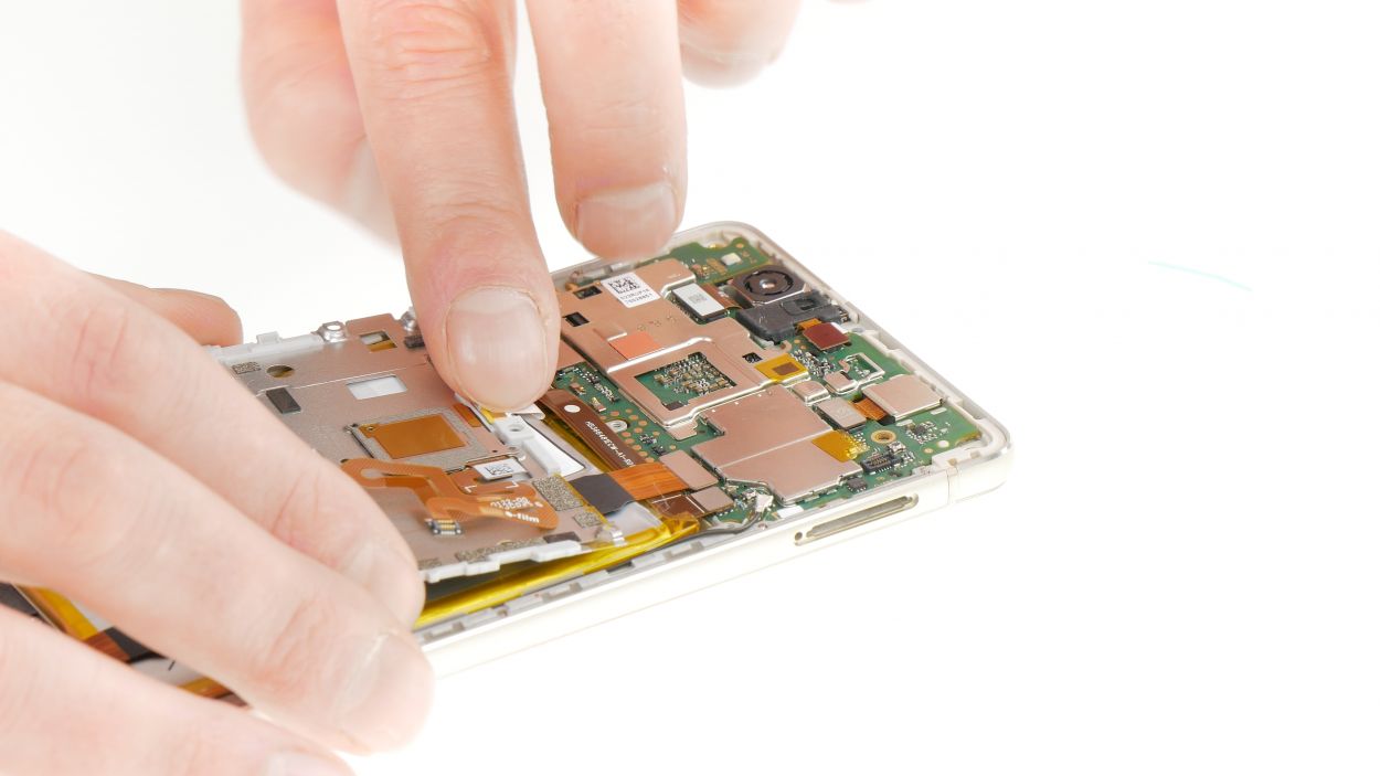
Step 13
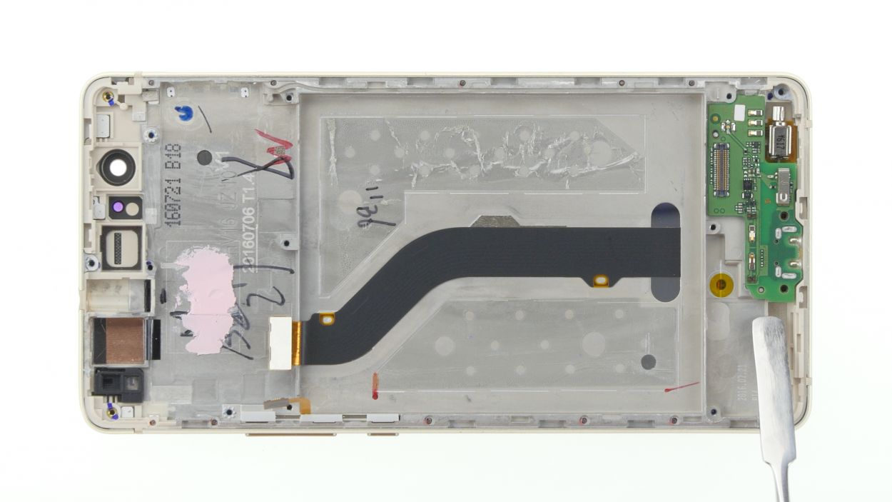
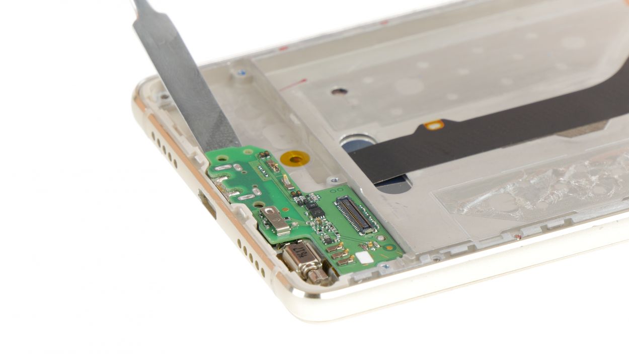
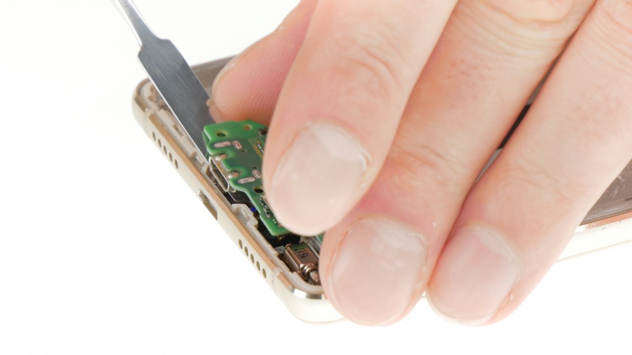
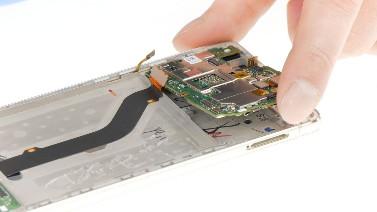
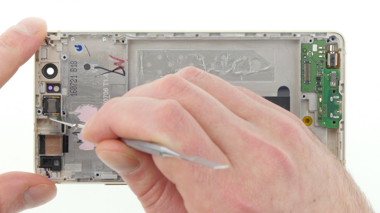
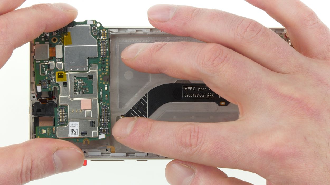
– Gently work your way around the circuit board with your trusty tool to pop it off like a pro.
– Carefully lift the circuit board away from the display unit and set it aside.
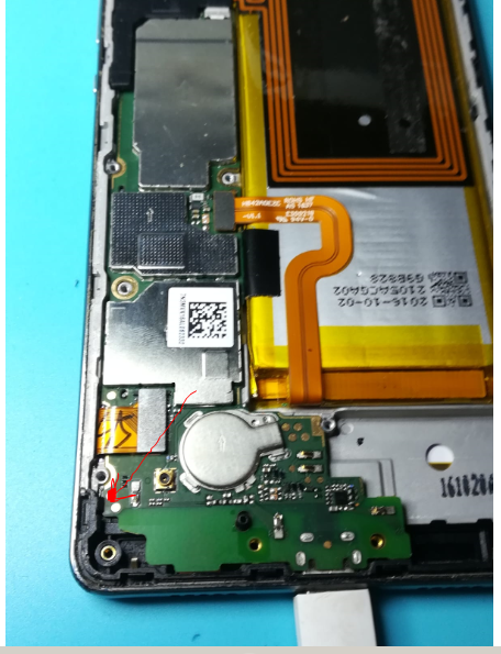
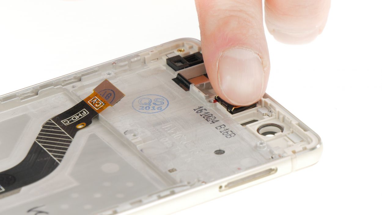
Step 14
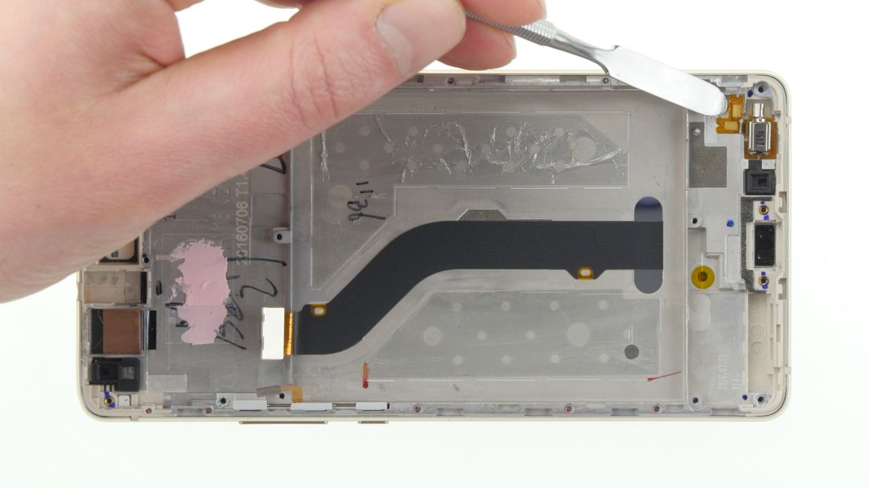
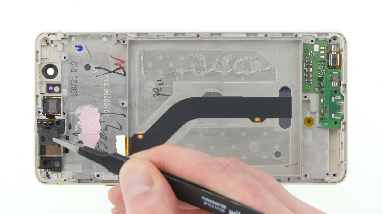
– 1. Gently pop out the vibration motor and detach it from the display unit. Just a heads up, it’s got some glue holding it in place, so be careful!
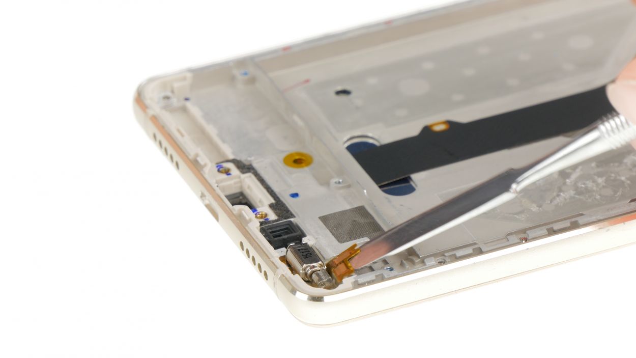
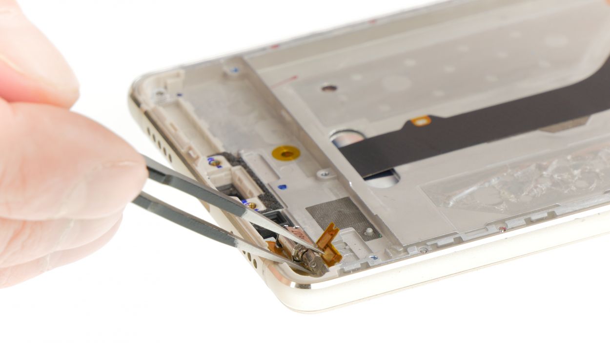
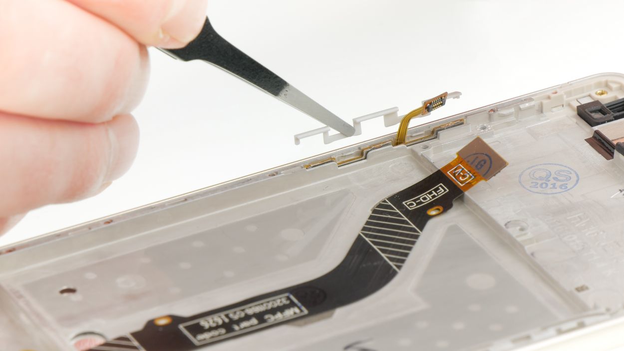
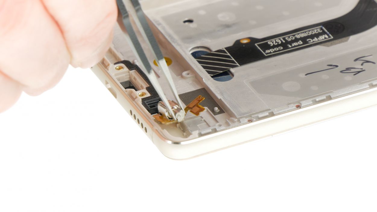
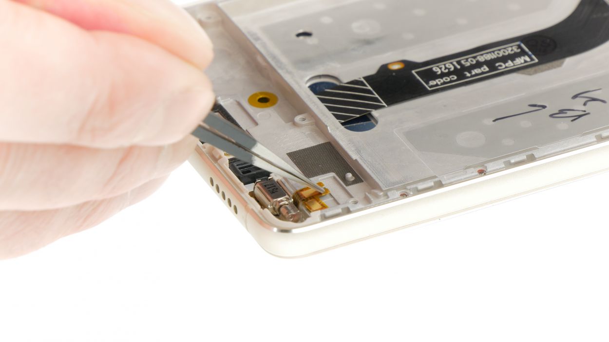
Step 15

– First, let’s get that plastic cover off. It’s time to say goodbye to the outer layer!
– Next up, gently wiggle out the cable set, including those volume keys, using a flat tool. Just slide it between the cable and the frame, and take your time loosening that glue. You’ve got this!
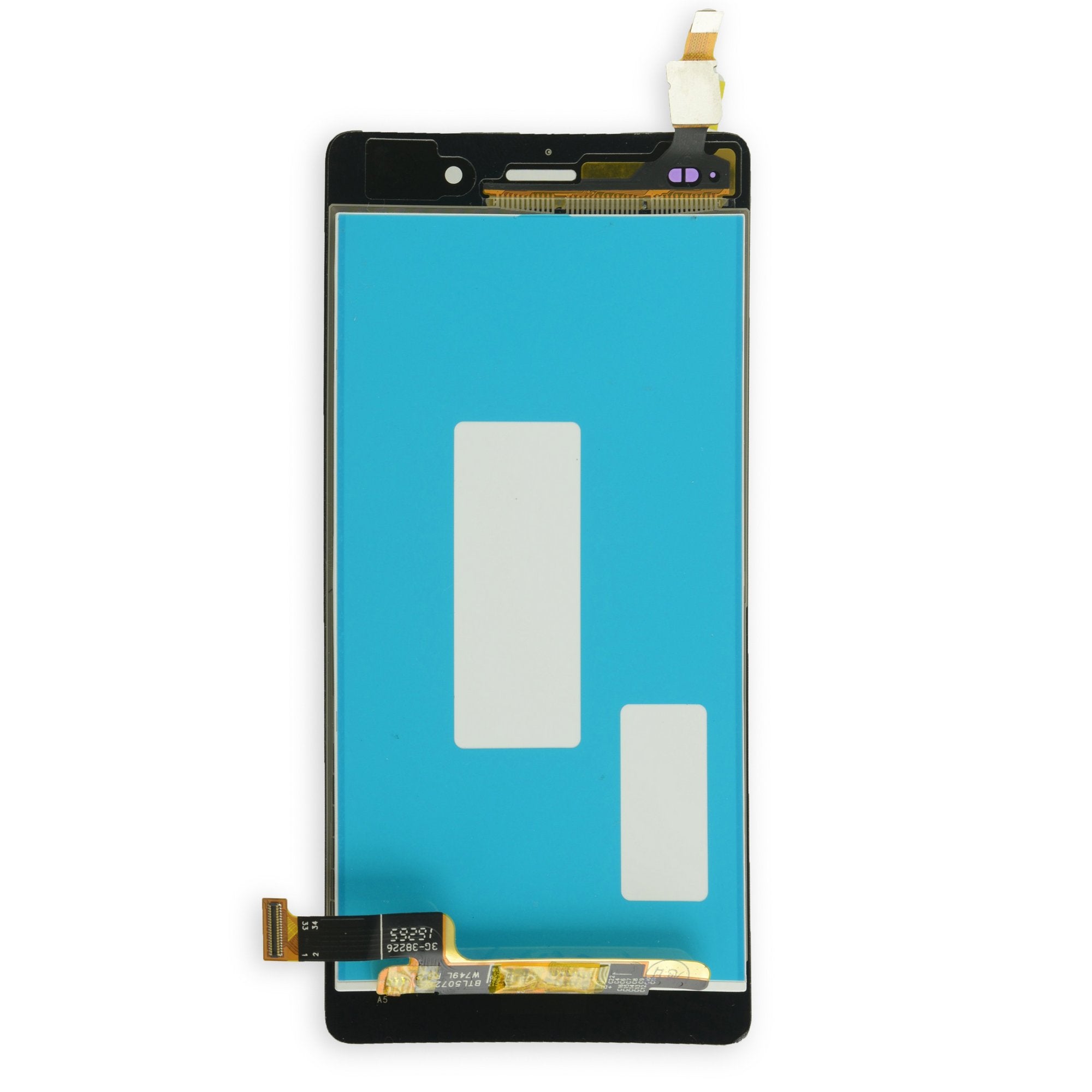
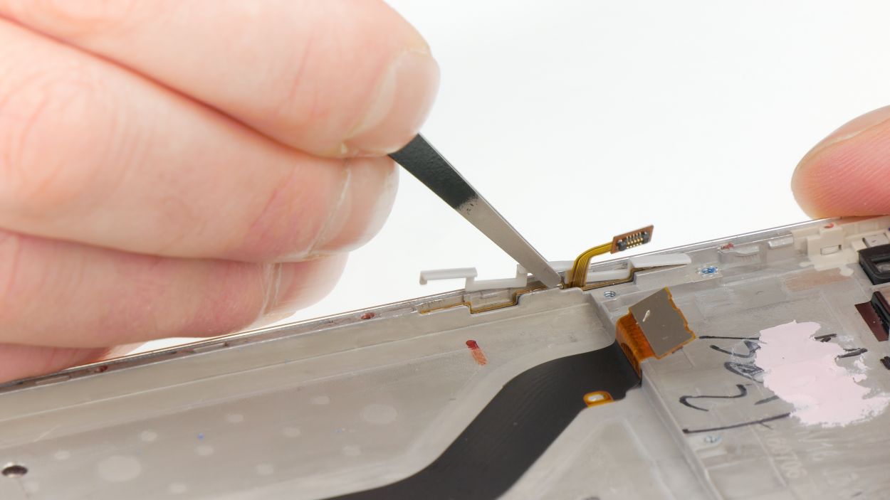
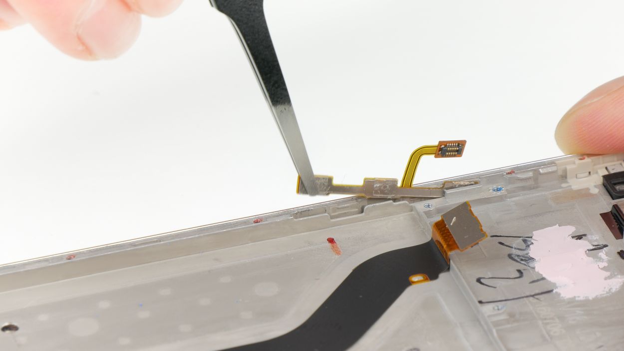
Step 16
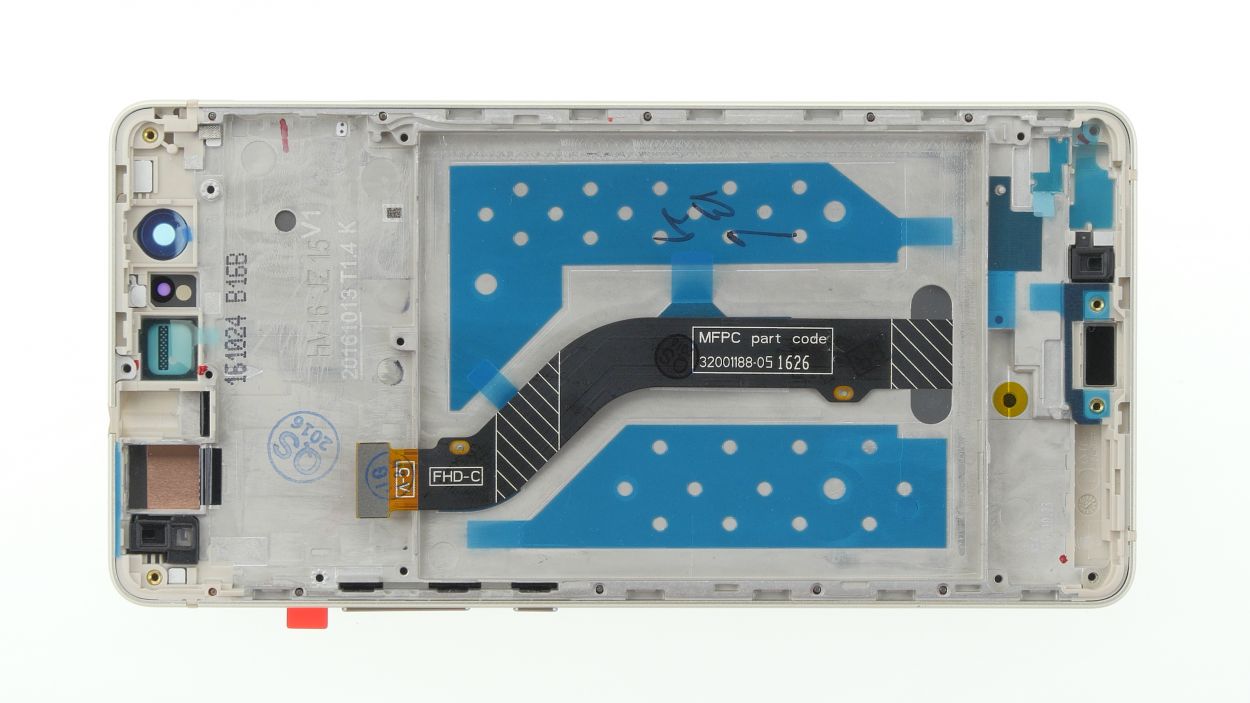
– First up, let’s peel off those pesky foils covering the display flex cable.
– Now, give that display flex cable a nice press down to secure it with some glue.
– And finally, remove all the protective films from your shiny new display unit. You’re almost there!
Step 17

– Time to get those volume keys and the cable set snugly inserted into the display unit. Let’s make it happen!
– Now, grab that plastic cover and snap it over the cable set. Give it a little press to secure it in place. You’ve got this!
Step 19
– Press down the latch on the lower circuit board near the USB port and give it a little nudge to lock it in place.
Step 21
– Pop that audio port into the display unit and give it a little press to make sure it’s nice and snug.
– Nestle the rubber gasket onto the audio port and make sure it’s just where it needs to be.
Step 22
– Time to bring your mainboard and display unit together! Gently insert the mainboard, making sure to bend back any cables that might get in the way.
– Give the mainboard a firm press until you hear that satisfying click.
– Now it’s time to connect the volume keys, display, and audio port to the mainboard. Place them carefully on their sockets and gently press them in.
Step 23
– Pop that rear camera right into the display unit, and make sure it’s snug as a bug!
– Connector
Step 25

Flex cable connector
2 × Antenna plug
– Let’s get that antenna cable snugly fitted into the display unit!
– Time to connect those antenna cable plugs to both circuit boards. Start by hovering each plug right above its socket and give it a gentle press until you hear that satisfying click!
– Now, let’s slide that large flex cable back into its cozy spot between the two circuit boards.
– Carefully connect the connectors to each circuit board. Remember, these two connectors are unique, so make sure the arrow is pointing towards the mainboard (that’s the top side)!
Step 26
3 × 2.9 mm Phillips
4 × 3.8 mm Phillips
– Pop that plastic cover with the speaker right into the display unit and give it a little press until you hear that satisfying click!
– Now, grab those seven Phillips screws and fasten them up. Just a heads up: they come in two different lengths, so keep an eye out!
Step 27
Battery connector
– Gently connect that battery flex cable! Make sure the connector is lined up just right before you give it a little press. It should snap into place with a satisfying click. If it’s being stubborn, don’t hesitate to give it another go.
Step 28

9 × Phillips
– Place the cover underside facing up on the battery and stick the NFC antenna contact back in place. Use the tab on the contact to position it correctly.
– Carefully connect the connector of the fingerprint sensor flex cable to the mainboard.
– Fold the cover onto the mainboard and press it on. Then use the nine Phillips screws to fasten it. The Phillips screws all have the same length.
Step 29
– 1. Set the back cover onto the display unit and give it a gentle press all around until it clicks securely in place.
Step 30
– Pop in any SIM or SD cards into the tray like a pro!
– Gently slide the SIM card tray back into its cozy slot.