DIY Guide to Replace iPhone 8 Lightning Connector
Duration: 30 min.
Steps: 38 Steps
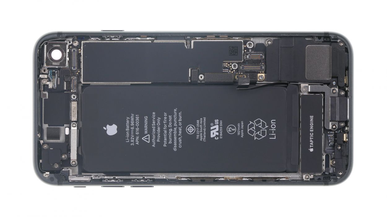
No need to stress! In this guide, we’re here to help you tackle those charging woes by walking you through the process of swapping out that faulty Lightning connector on your iPhone step by step. Wishing you all the best with your repair adventure! If you find our tips useful, we’d love to hear your feedback. Remember, you got this!
Step 1
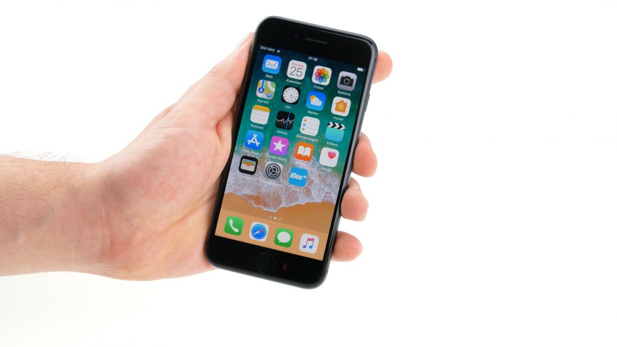
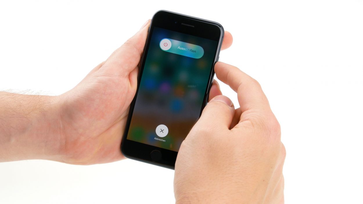
– Completely power down your iPhone to keep it safe from any sneaky short circuits. Just press and hold the standby button for about three seconds until the ‘Turn off’ slider pops up on your screen.
– Slide that slider from left to right and hang tight until your iPhone is fully off.
Step 2

– Gently unscrew the two Pentalobe screws flanking the Lightning Connector and stash them safely in your screw storage. You’re doing great!
2 × 3.4mm Pentalobe
To keep track of those tiny screws and parts you’ve removed, we suggest using a screw storage solution. An old sewing box can work wonders for this! Here at Salvation Repair, we like to use a nifty magnetic mat that helps us lay out the parts just like they were in the phone. This way, you’ll know exactly where each screw belongs, making reassembly a breeze!
Tools Used
Step 3
When it comes to heating your device, think of it like a warm hug – just enough to make it cozy without turning it into a scorched marshmallow! You want it to be warm enough for the adhesive to loosen, but still cool enough that you can comfortably touch it without jumping back in surprise.
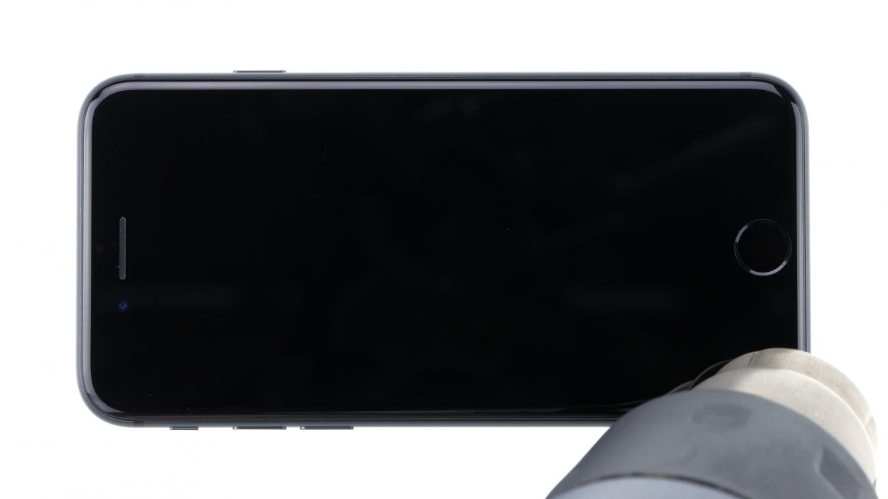
– First, set your iPhone 8 down on a soft, clean surface. We want to keep it scratch-free while we lift that display!
– Next, grab your hot air tool, whether it’s a fancy heat gun or just a regular hairdryer, and give the outside of the display a warm, even hug. This will help loosen things up for the next steps!
Tools Used
- heat gun to heat parts that are glued on so they’re easier to remove.
In most cases, you can also use a hairdryer.” rel=”noopener”>Heat gun
Step 4
Opening up your iPhone 8 means waving goodbye to that dust and splash protection warranty, plus the waterproof warranty too. So, proceed with a smile and a bit of caution!
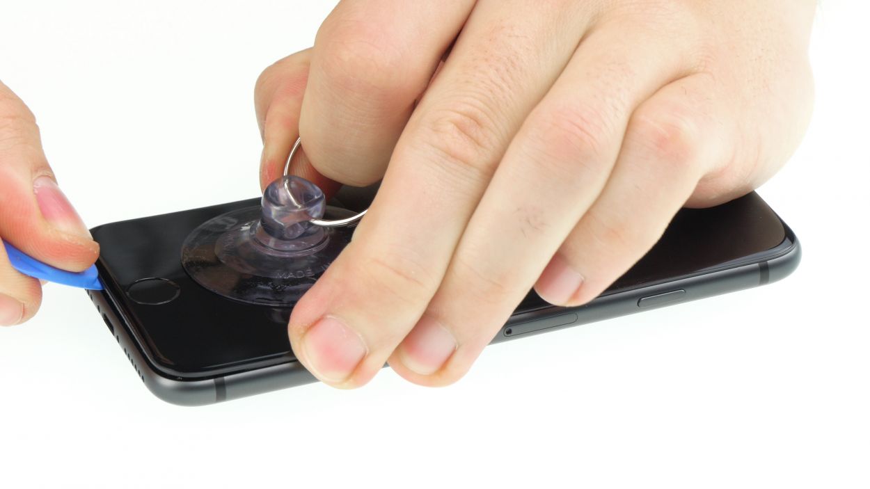
– Stick a suction cup on the display just above the Home button and give it a gentle tug upwards. This will create a little space between the aluminum and display frames—easy peasy!
– Next, slide a flat plastic tool into that newly formed gap. Give it a little nudge to widen the space by pushing the aluminum frame upwards. Flat plastic picks work wonders for this task!
Tools Used
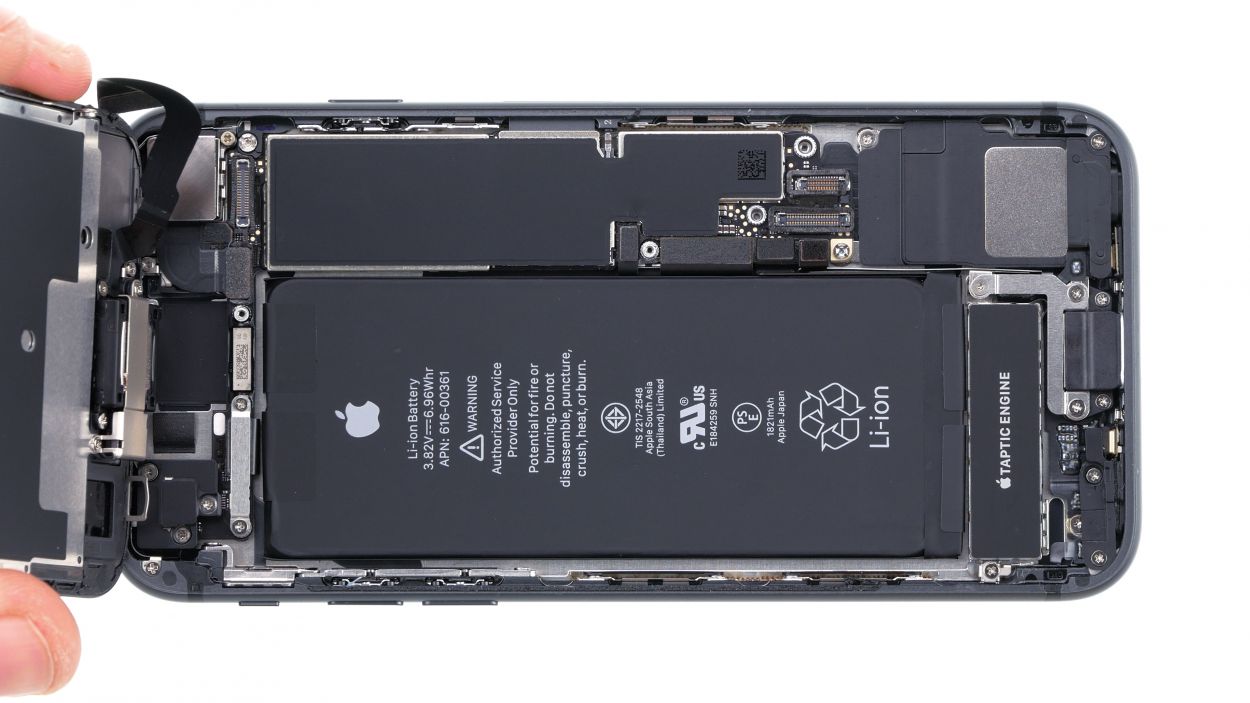
Step 5
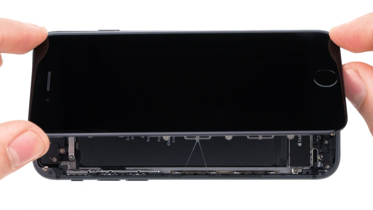
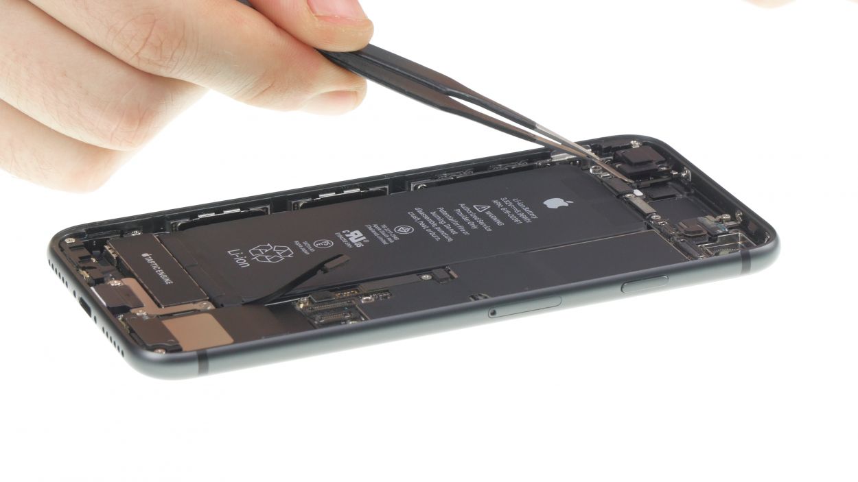
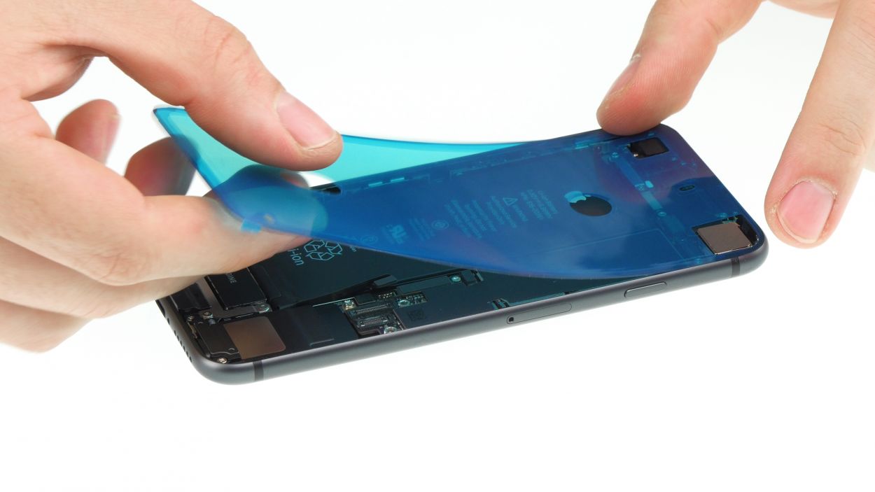
Keep it cool and remember, you can only open the display to a max of 180° while it’s still connected! Go beyond that, and you might just snap those delicate flex cables. So, let’s keep it steady and safe!
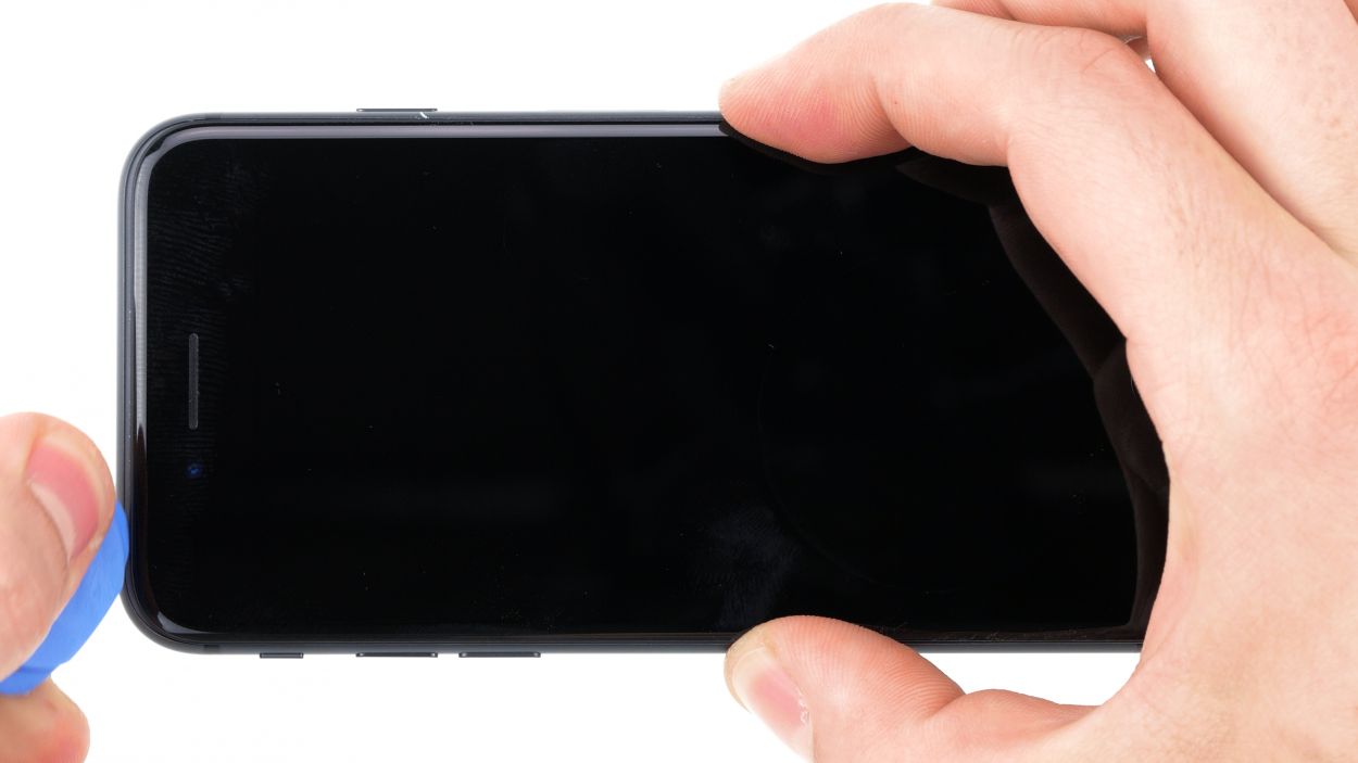
– With a gentle nudge, push the display upwards using your trusty plectrum to pop those lugs free from the aluminum frame. You’re doing awesome!
– Now, swing that display open towards the standby button. Lean it against something sturdy to keep those flexible cables from overstretching. You’ve got this!
Tools Used
Step 6
2 × 2.6 mm Phillips
2 × 1.0 mm Phillips
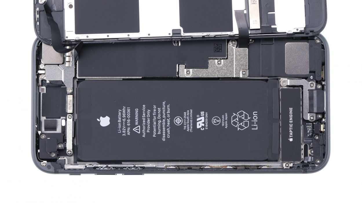
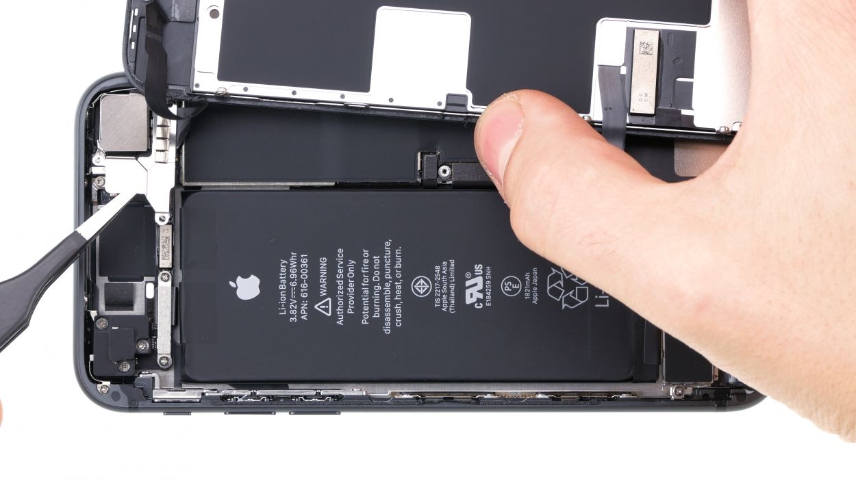
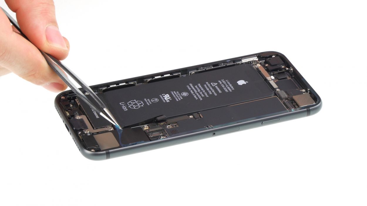
Before you dive into this repair, let’s give that battery connector a little love and disconnect it! This way, we keep short circuits at bay and avoid any accidental device wake-ups during your repair journey.
– Grab your trusty Phillips screwdriver and unscrew those four Phillips screws like a pro! Once they’re out, gently lift off the cover using your tweezers—easy does it!
– Next up, it’s time to disconnect the battery connector. Use a plastic spudger to carefully pry it off. You’ve got this—just take it slow and steady!
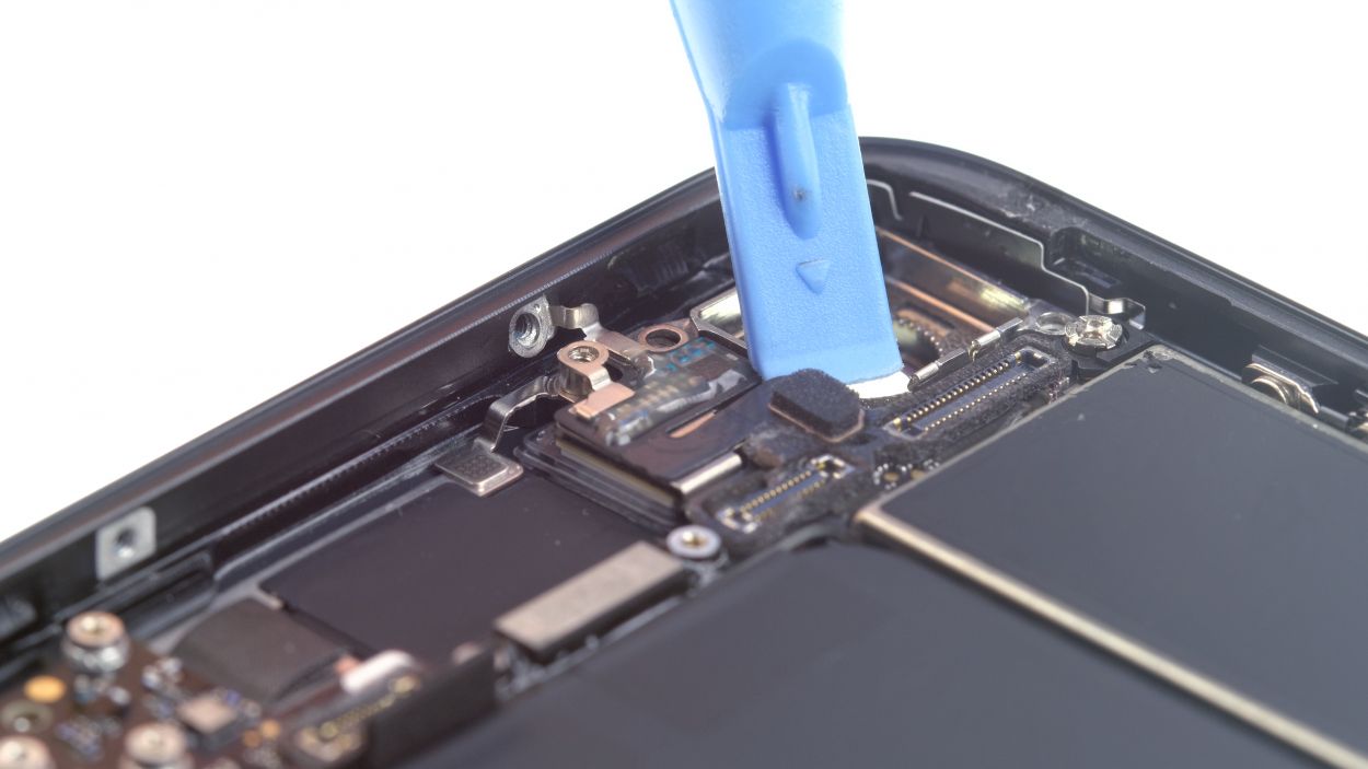
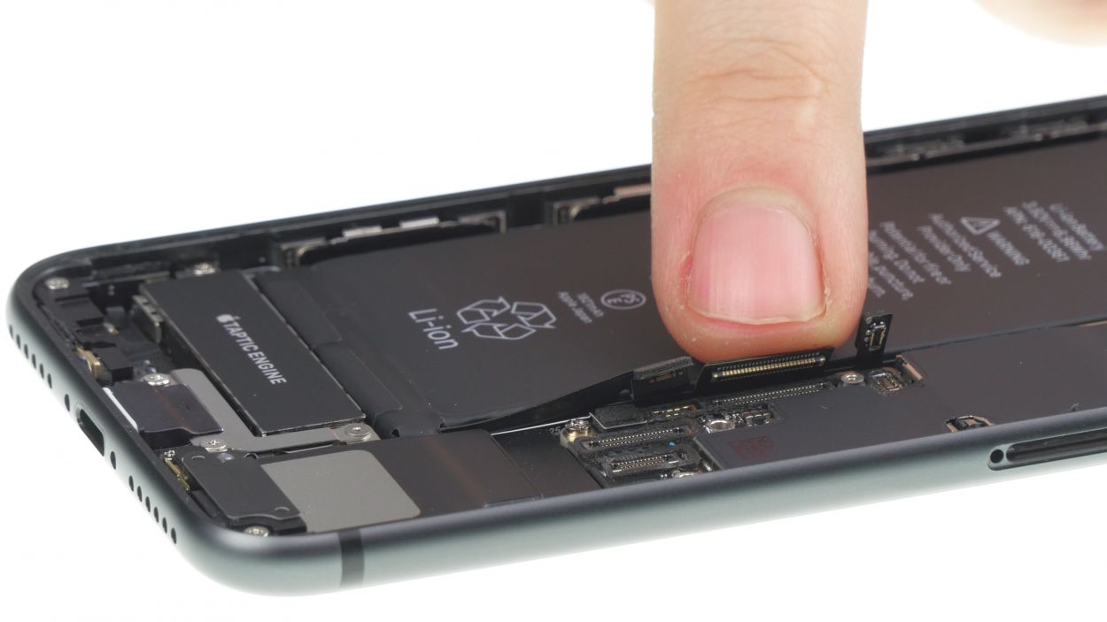
Step 7
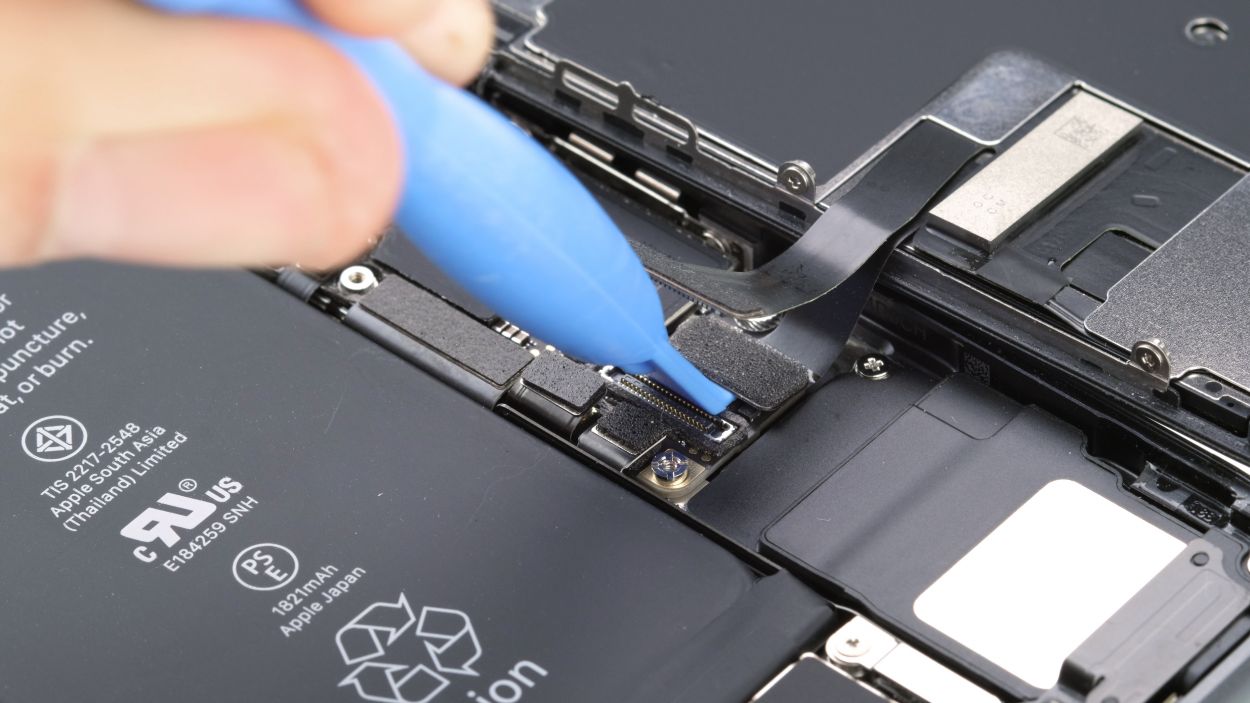
– Grab that trusty spudger and give those display connectors (both the display and home button) a little nudge to disconnect them. You’re on the right track!
Tools Used
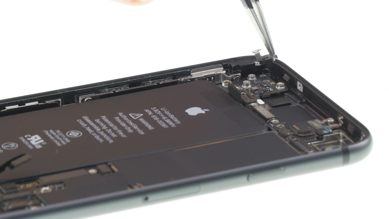
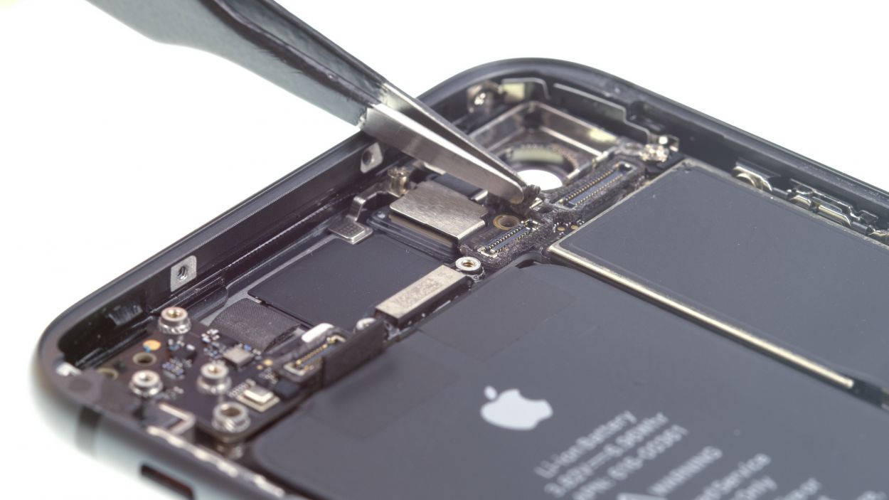
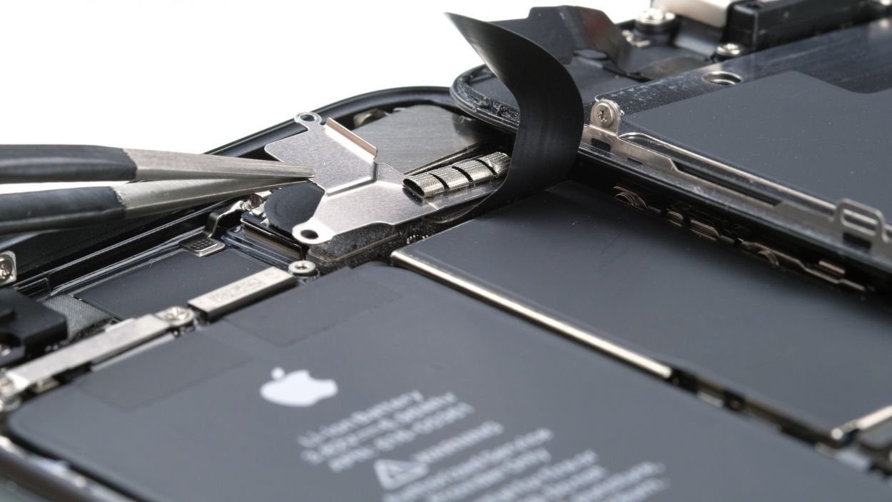
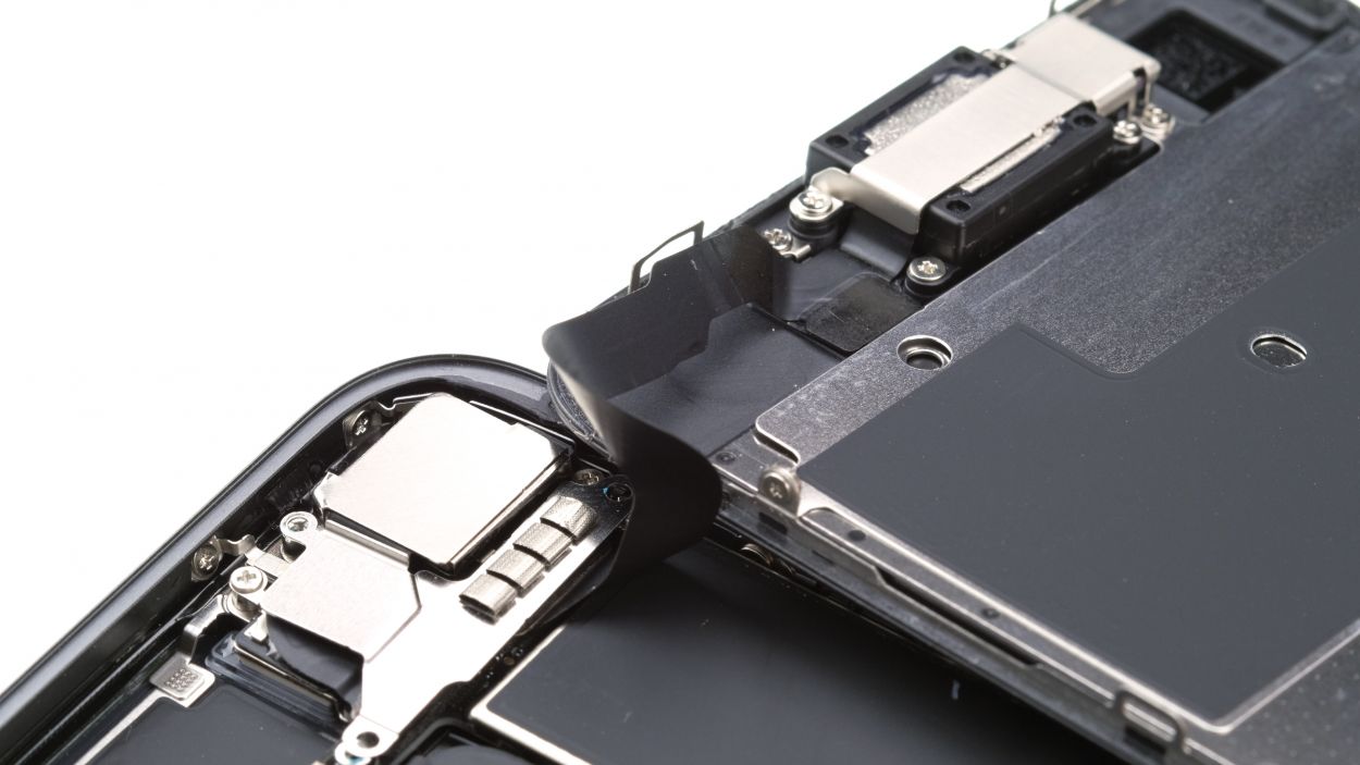
Step 8
3 × 1.0 mm Phillips
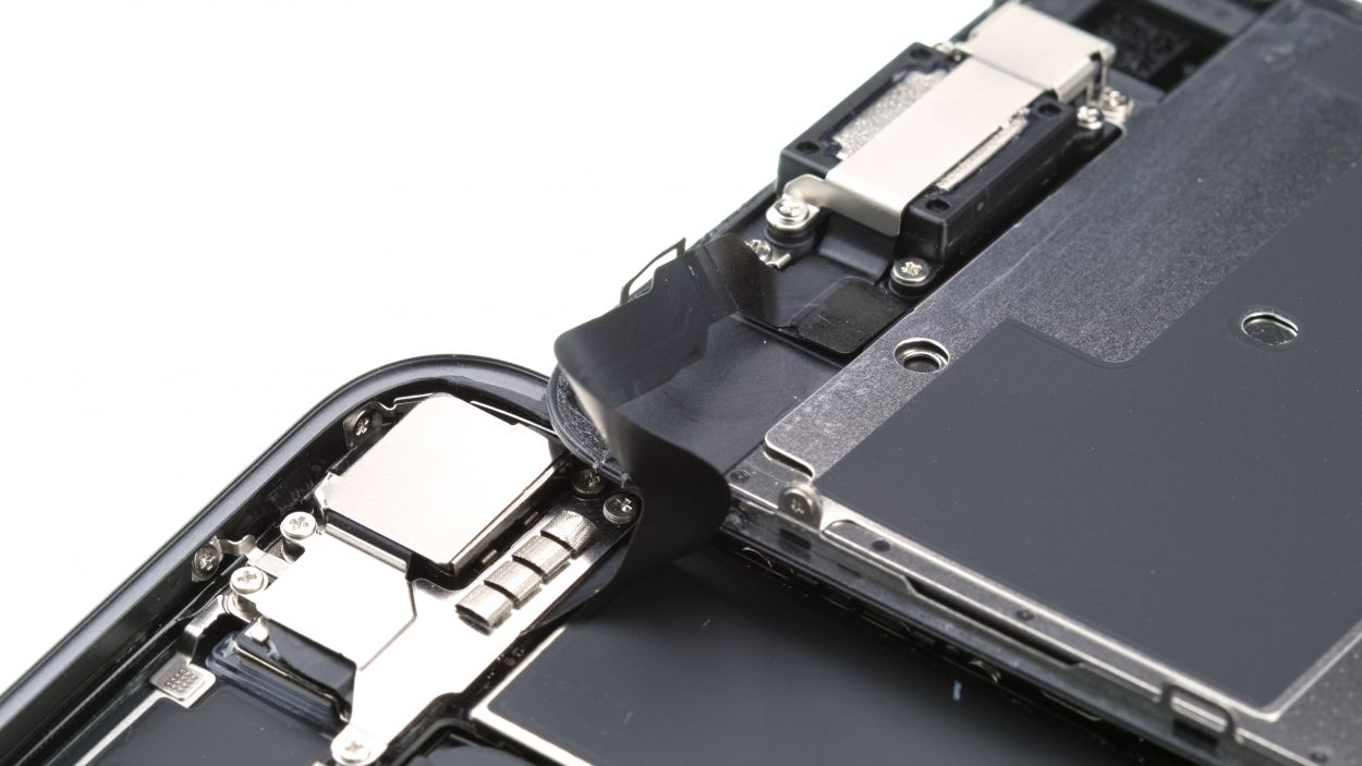
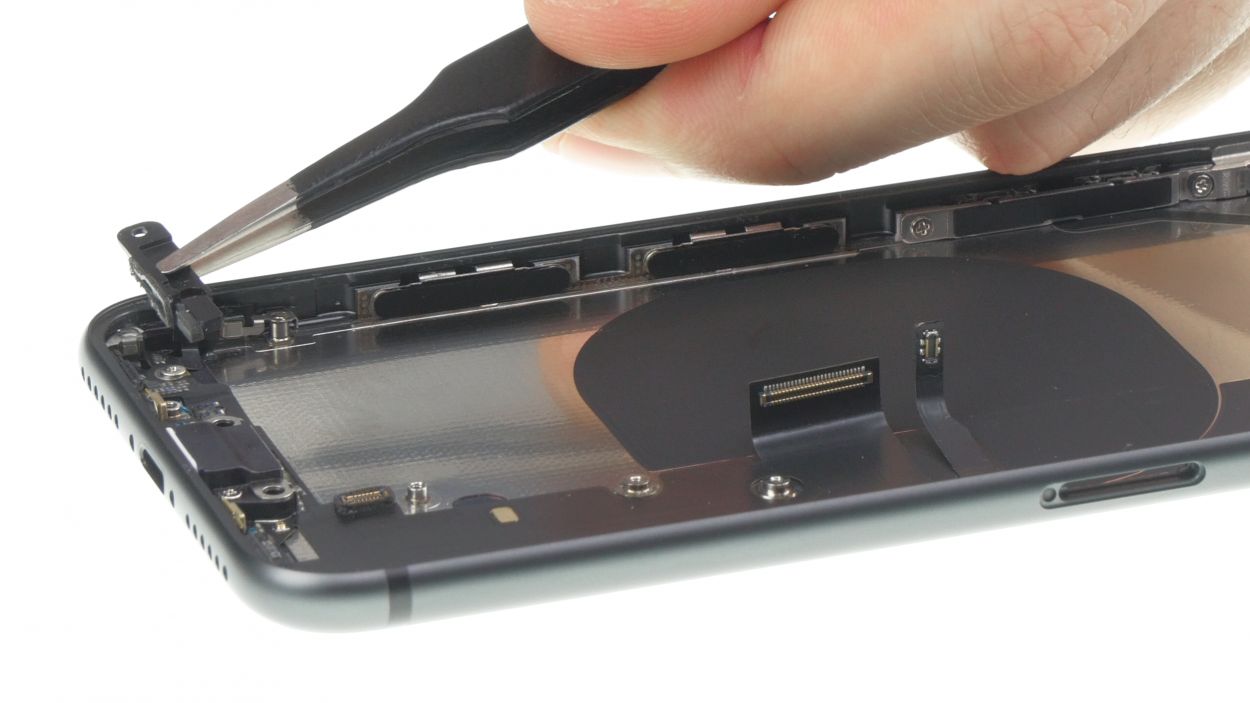
– Unscrew the three Phillips screws that are holding the cover plate above the connector. You’ve got this!
– Using your tweezers, gently lift off the cover plate from your iPhone 8. Easy peasy!
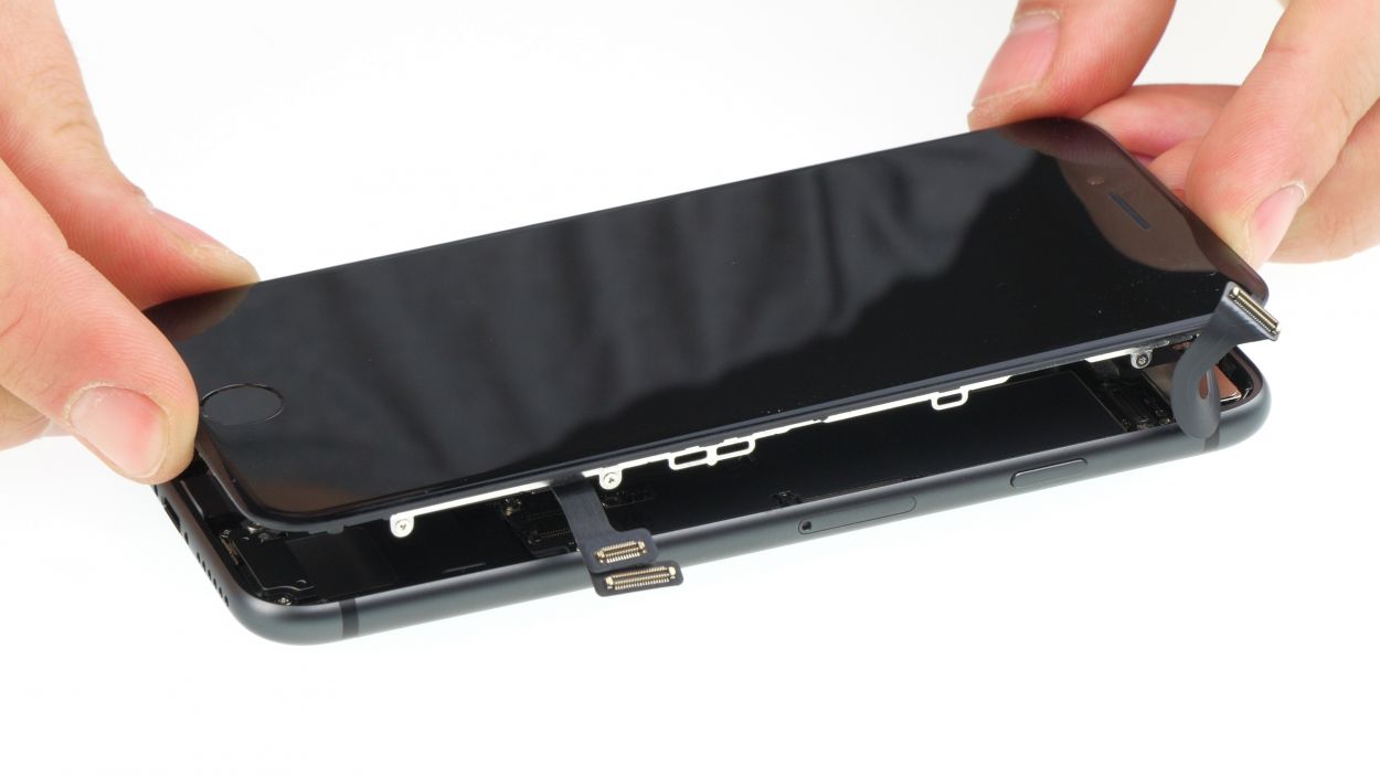
– With care, use a spudger to separate the FaceTime connector from the board. You’re doing great!
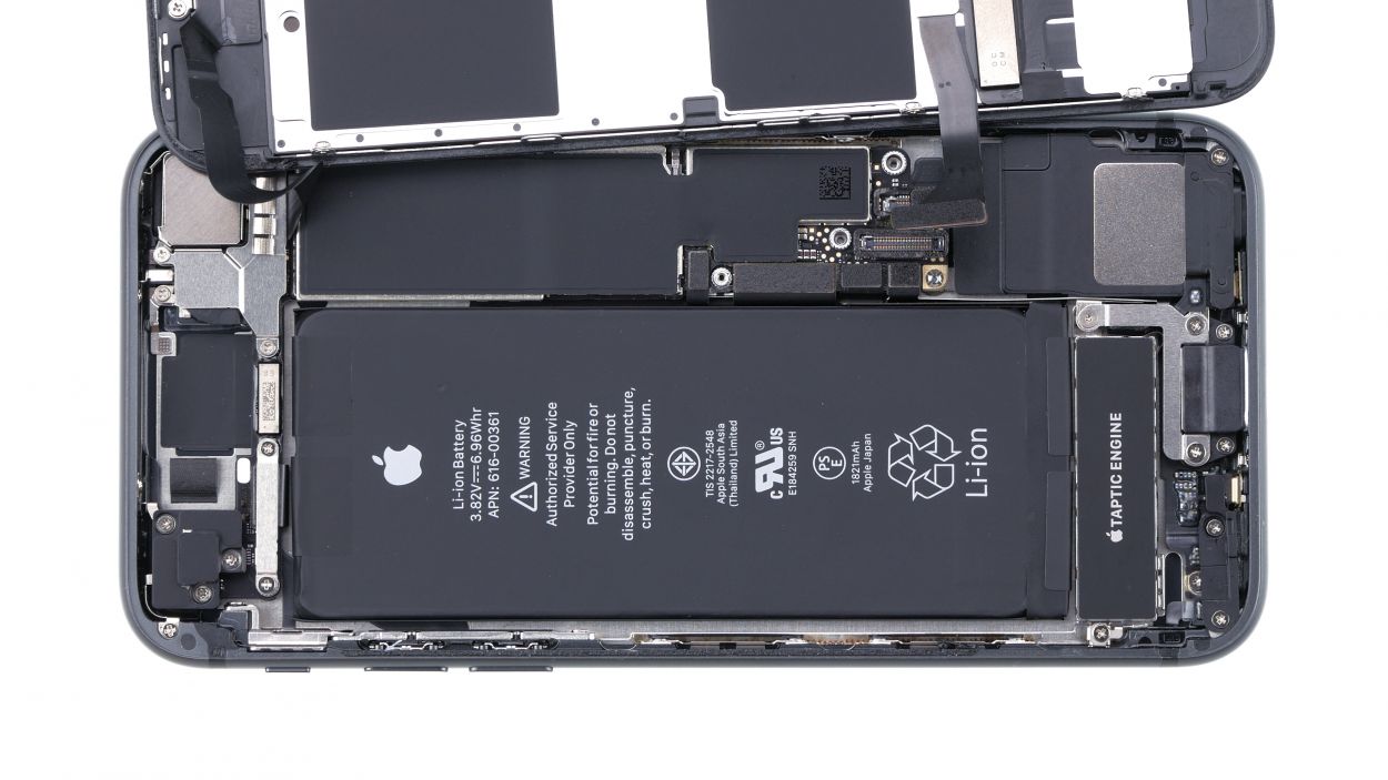
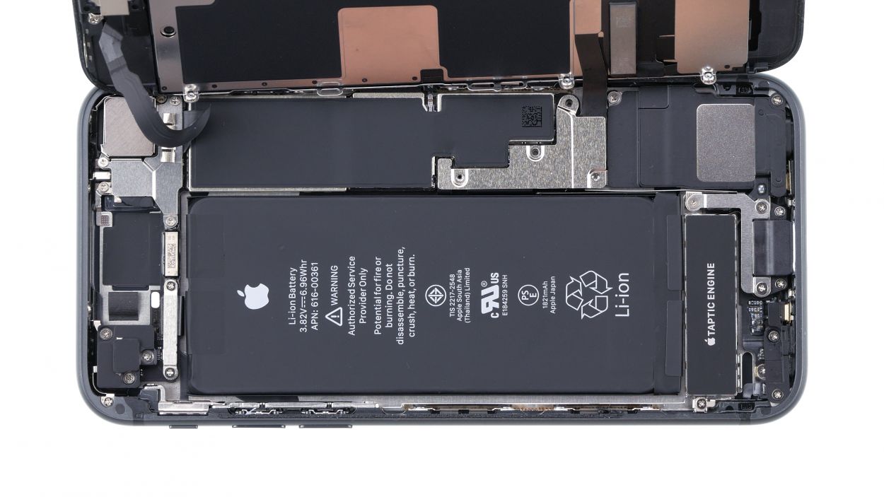
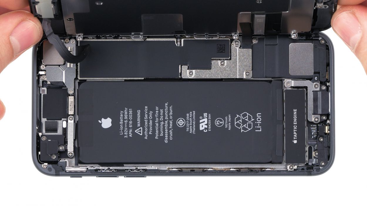
– And just like that, you can completely remove the display now. Nice work!
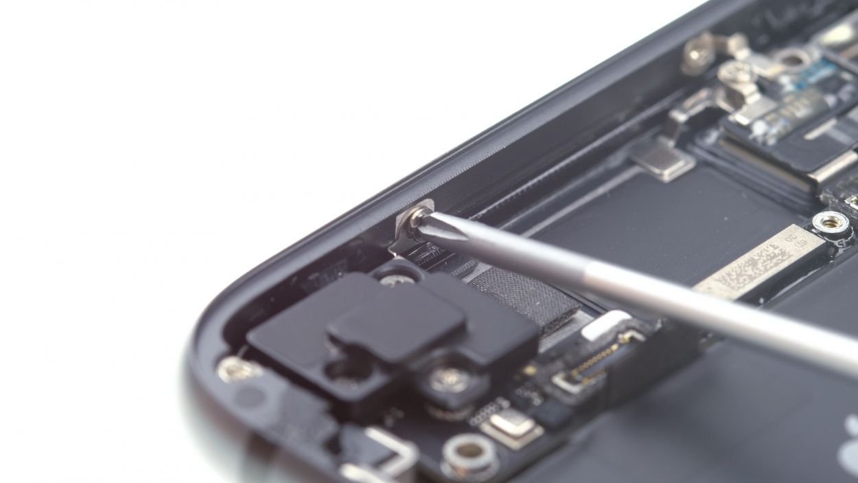
Step 9

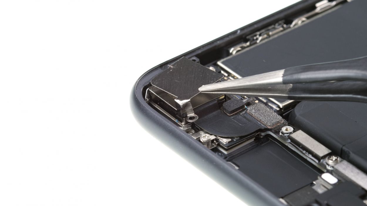
1 × 2.9 mm Phillips
1 × 3.0 mm Standoff
Got a stand-off screw giving you a hard time? No worries! While there are special screwdrivers made just for it, you can totally get by with a regular, narrow slotted screwdriver. Keep it cool and you’ll be just fine!
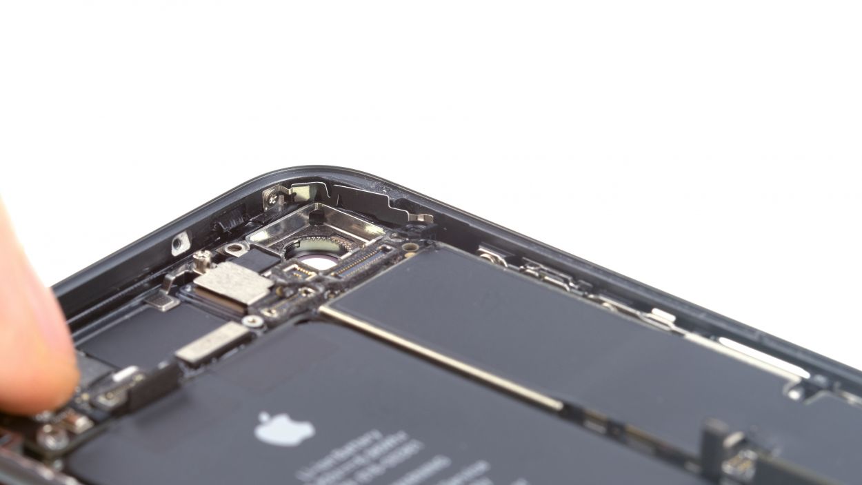
– Unscrew the screws and take off the cover plate of the iSight camera. You’ve got this!
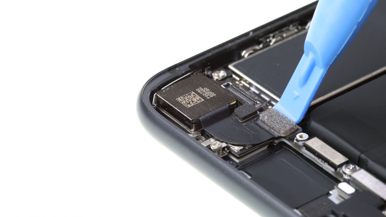
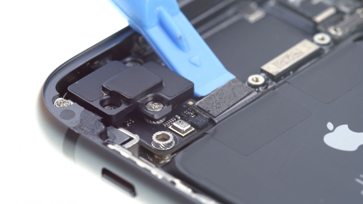
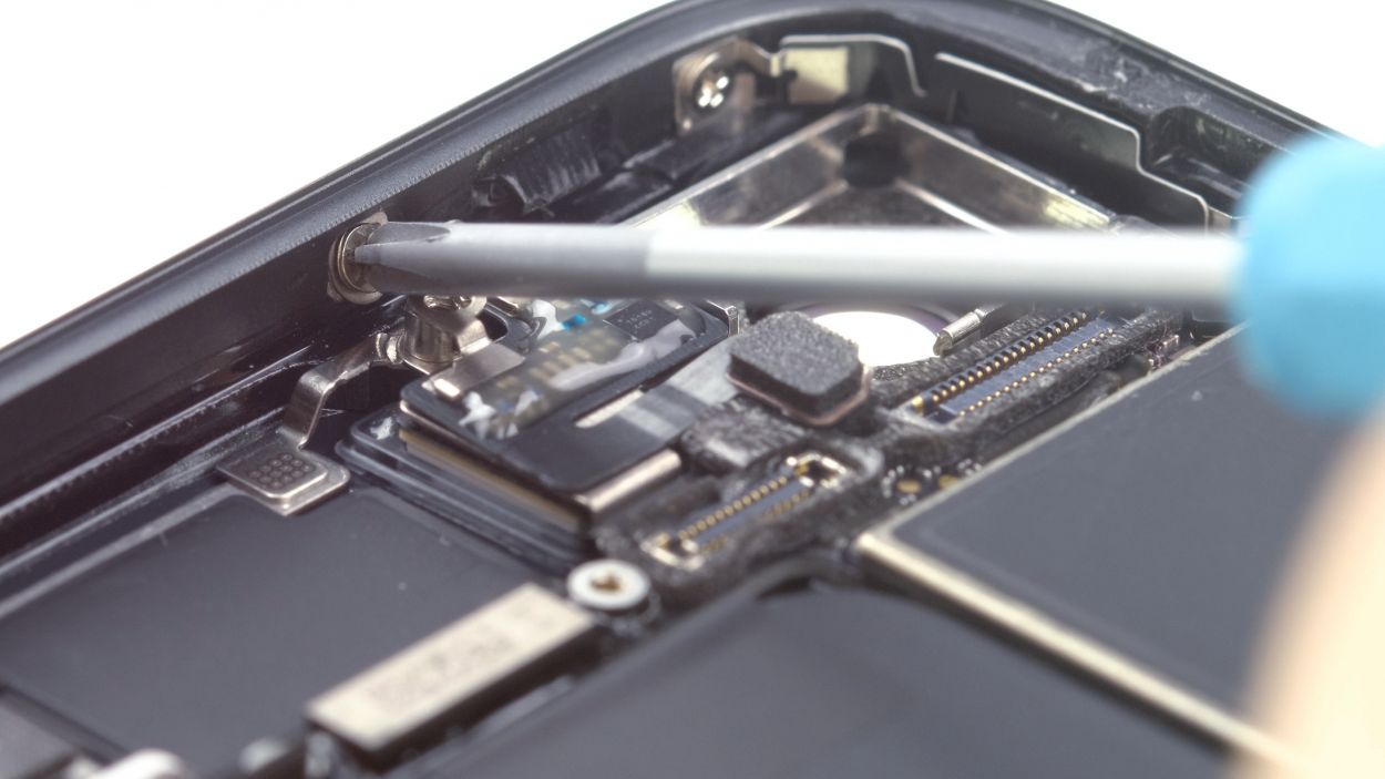
Step 10
1 × 1.1 mm Phillips
1 × 2.7 mm Phillips
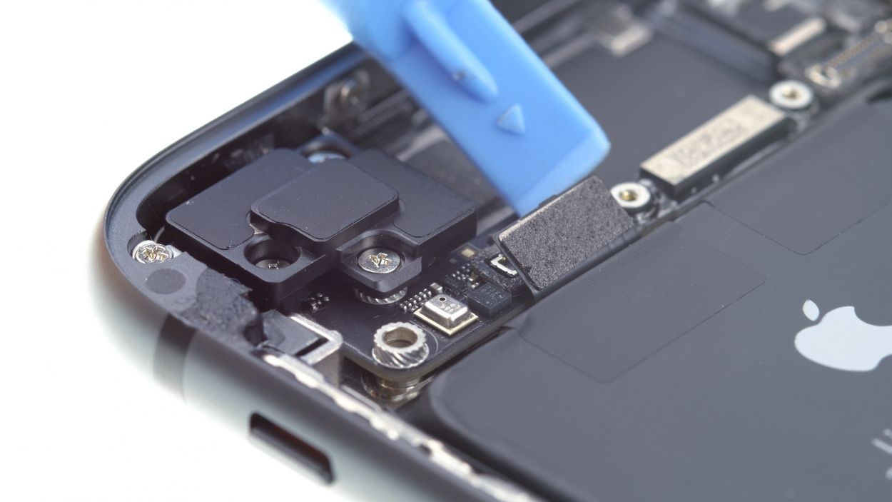
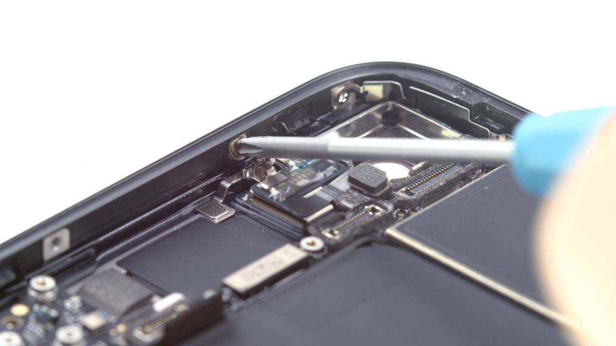
– Start by unscrewing the screws that are holding the bracket plate in place. You’re on the right track!
– Next, gently lift that bracket plate out of your device. You’re doing great!
– Now, it’s time to disconnect the connector from the logic board. Use a plastic spudger to carefully pry it off. Just take your time and be gentle!
Step 11
2 × 1.2 mm Philliips
2 × 1.0 mm Philliips
1 × 2.5 mm Phillips
1 × 1.4 mm Phillips
One of the screws is giving a cozy hug to the side of the back cover. Just a little twist and you’ll have it free!
– First, give those screws on the plastic bracket a little twist to loosen them up. You’re on the right path!
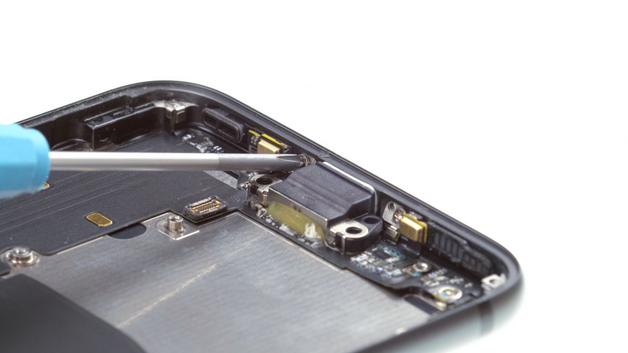
Step 12
1 × 1.3 mm Phillips
1 × 1.2 mm Phillips
– First, let’s unscrew those Phillips screws holding the antenna in place. You’ve got this!
– Next up, gently disconnect the connector from the board. Easy peasy!
– If the antenna is feeling a bit stubborn, give it a little warmth with a heat source and carefully pry it off with your spatula. Just like that, you’re on your way!
Step 13
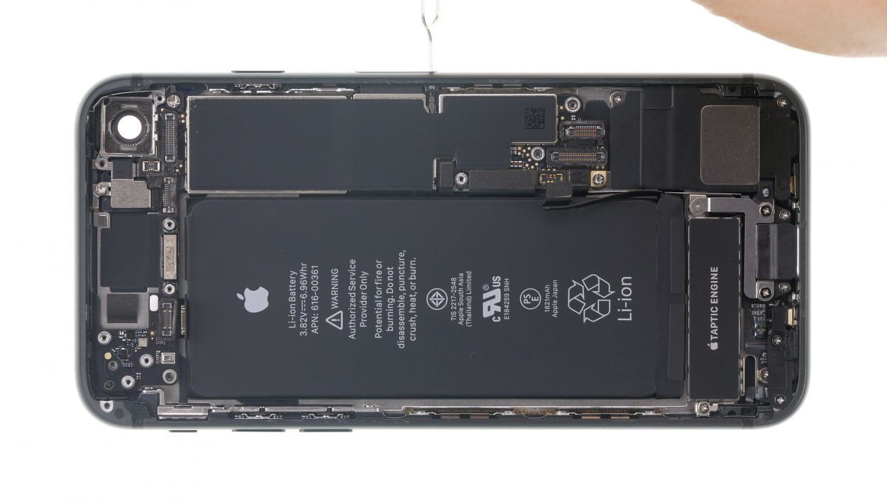
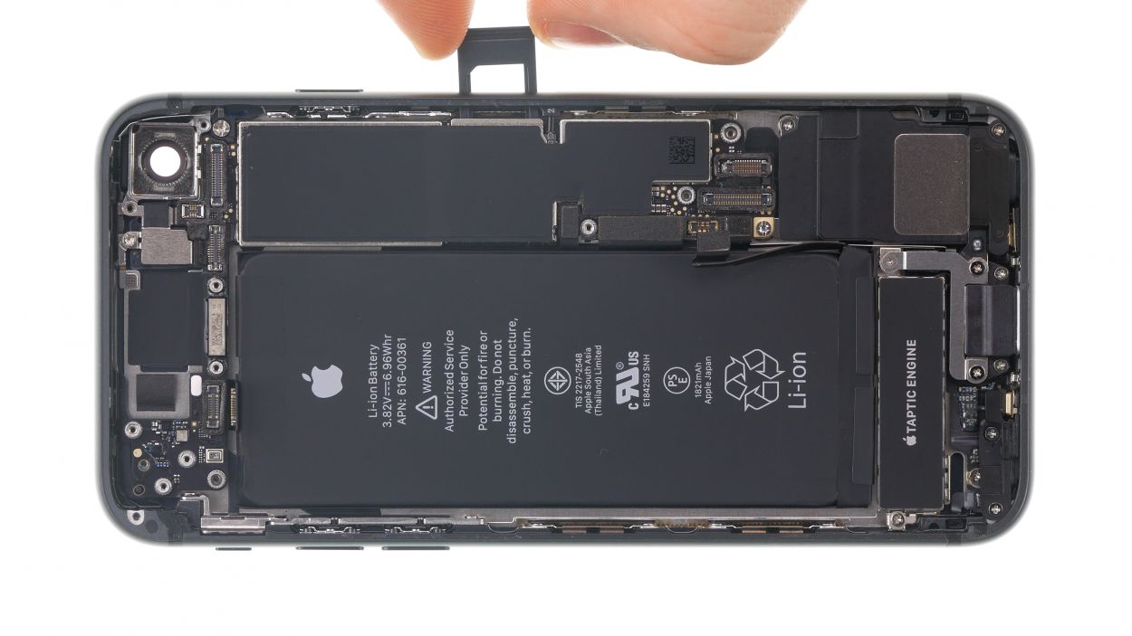
– Grab your trusty SIM tool or a paper clip to pop that SIM card holder right out! Just press the tool into the tiny hole next to the SIM card holder and voilà!
Tools Used
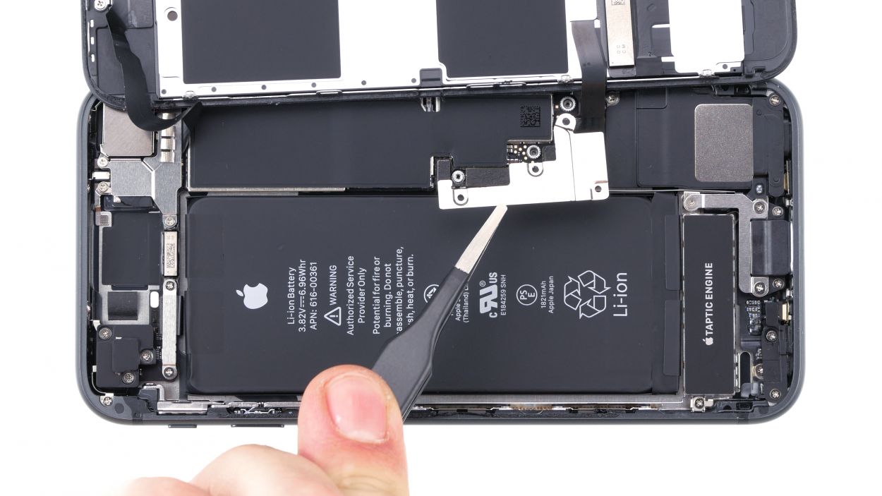
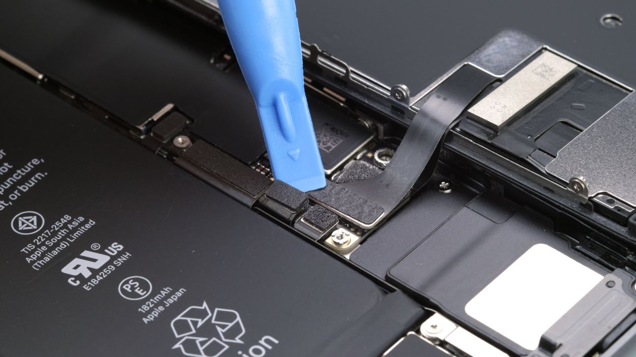
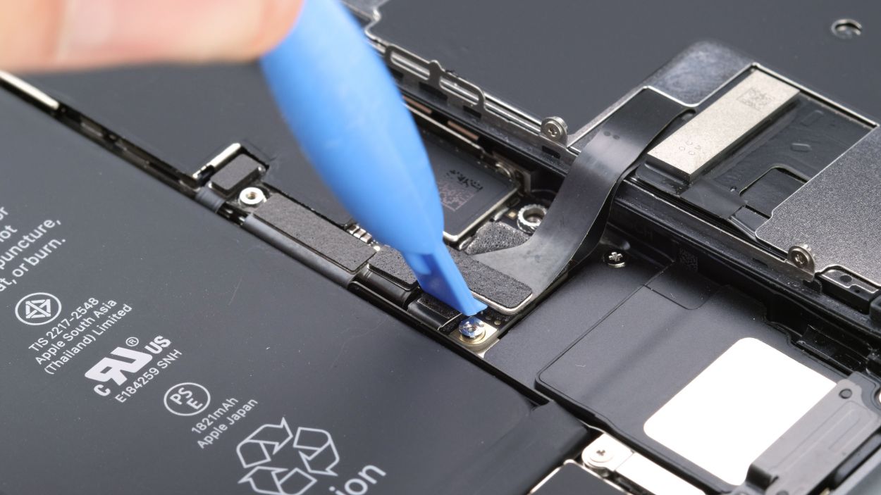
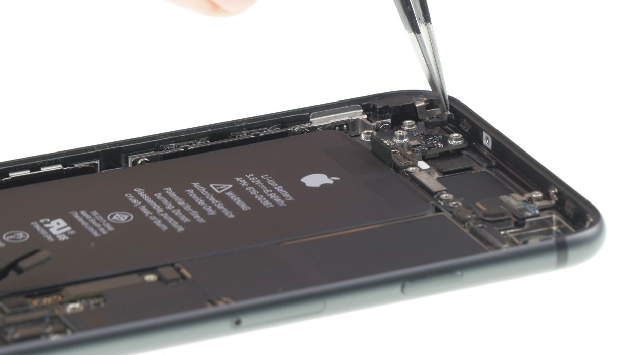
Step 14
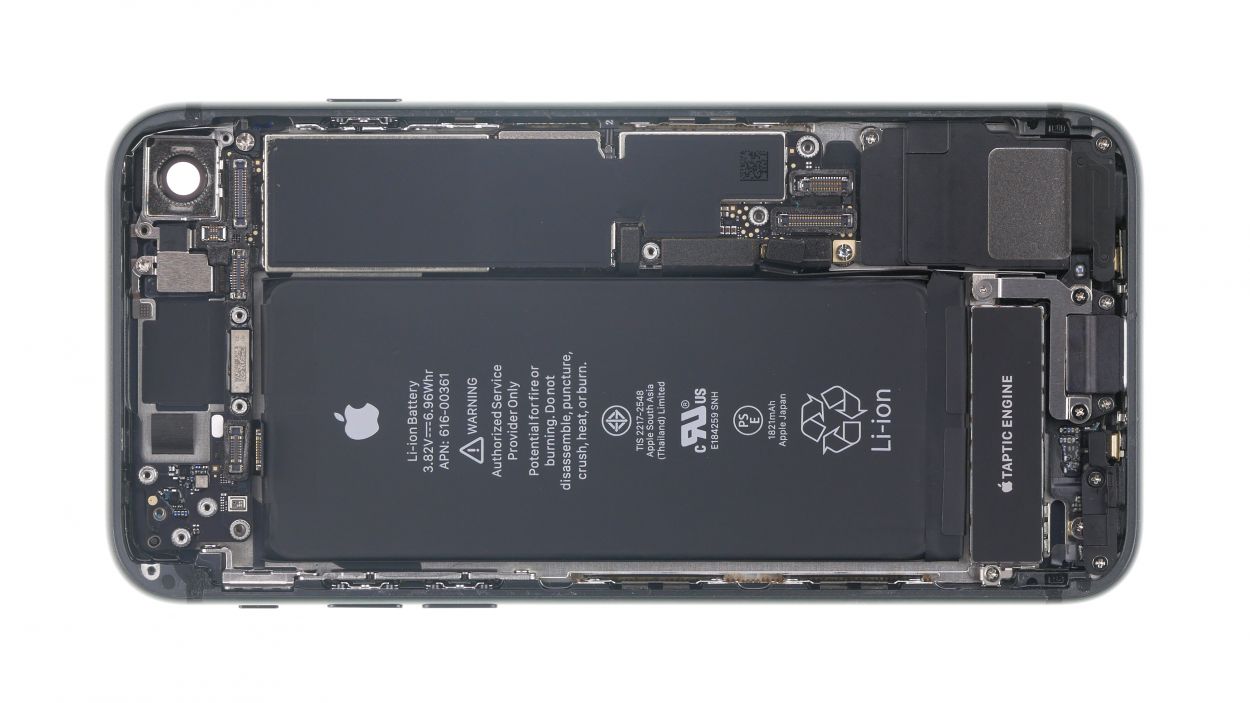
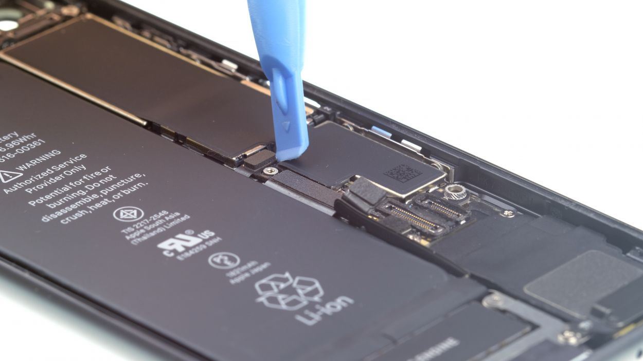
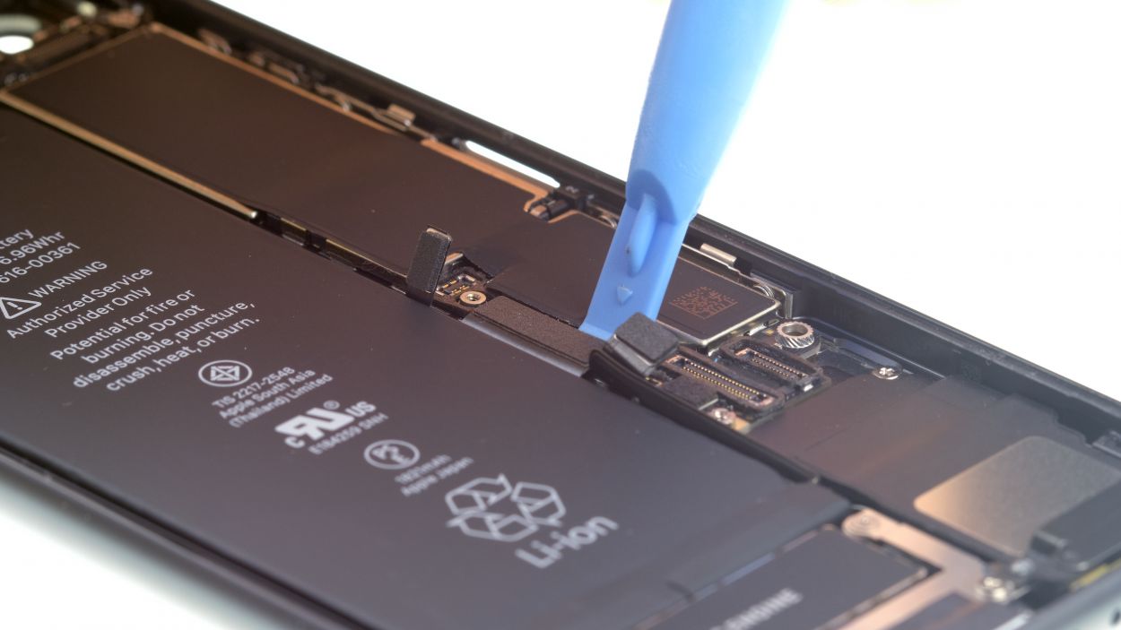

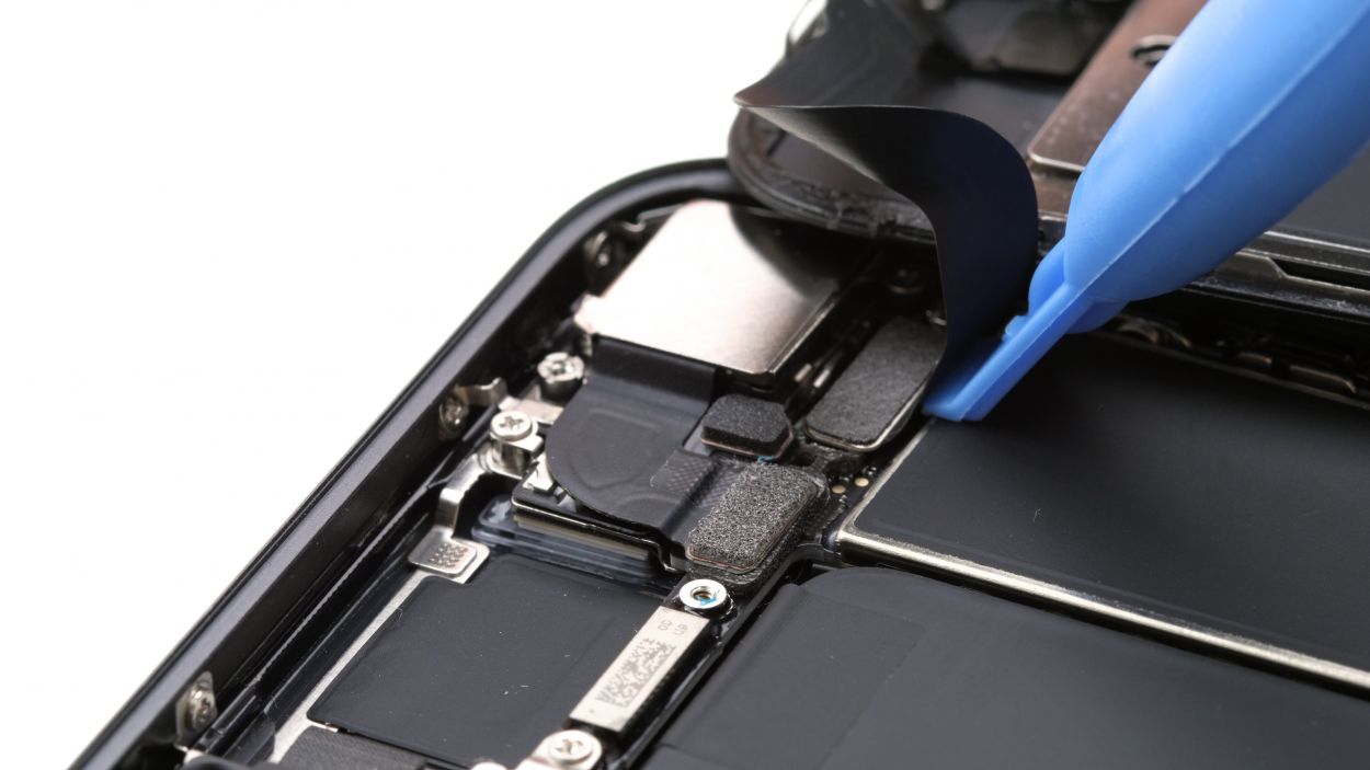
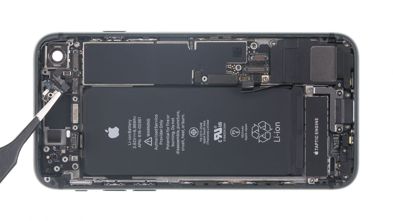
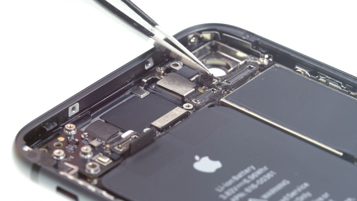
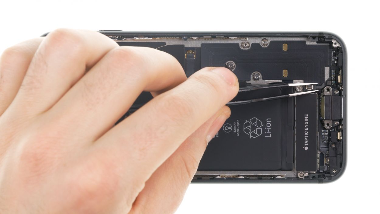
– Grab your trusty spudger and gently wiggle it to disconnect those three connectors on the battery side of the logic board. You’re doing great—keep it steady!
Tools Used
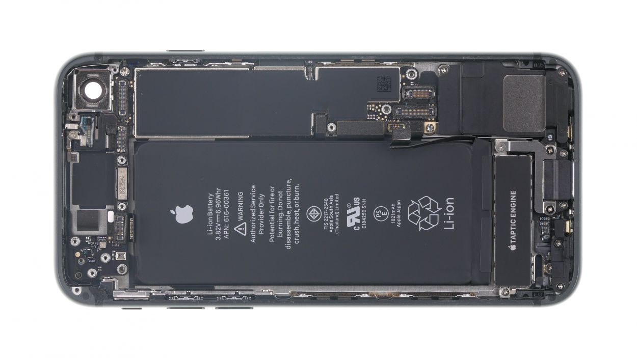
Step 15
1 × 2.4 mm Standoff
1 × 2.1 mm Standoff
1 × 1.6 mm Phillips
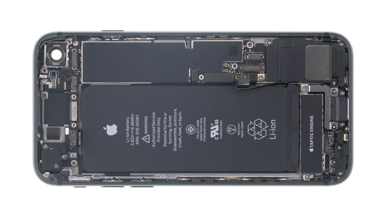
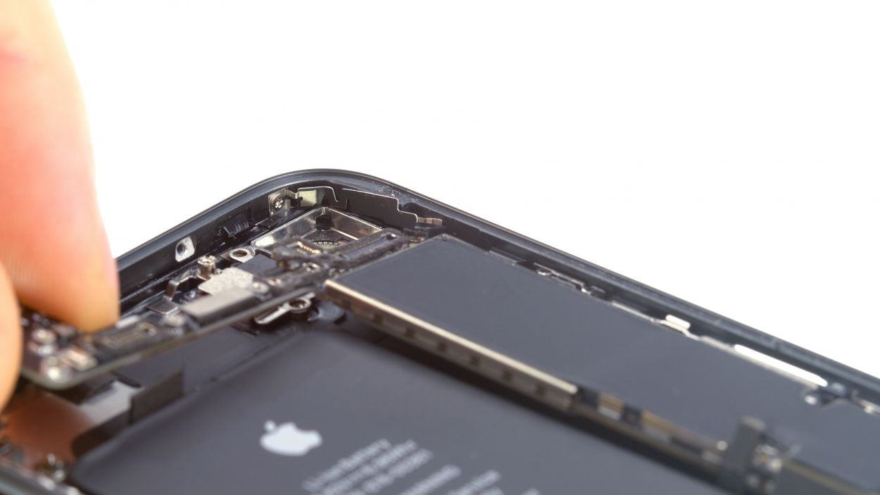
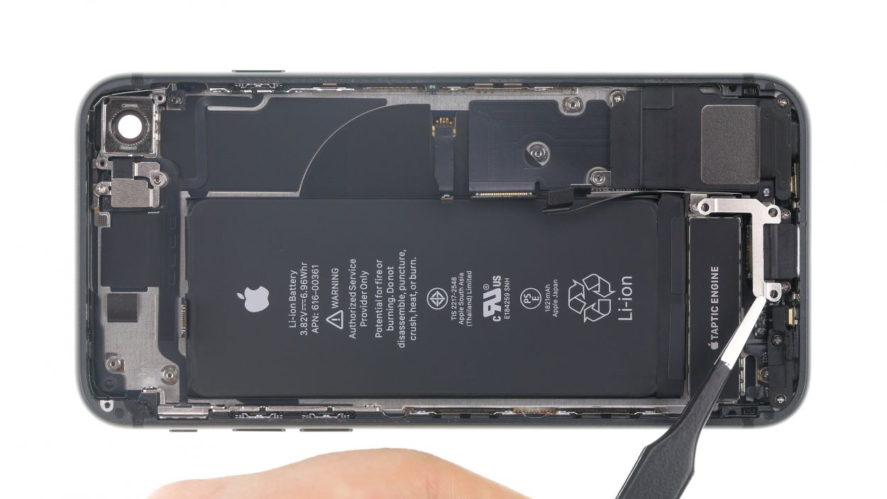
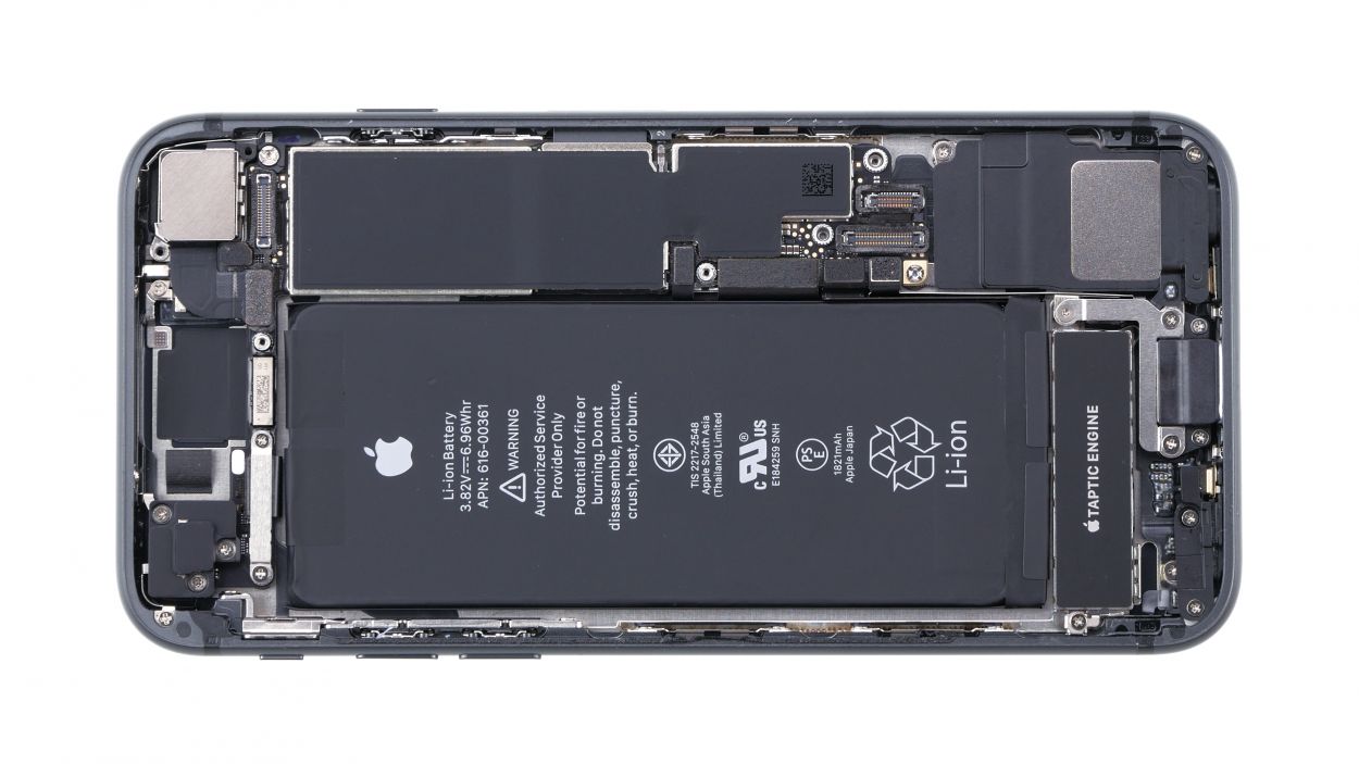
The Phillips screw is playing hide and seek under a sticker (check out the photo!).
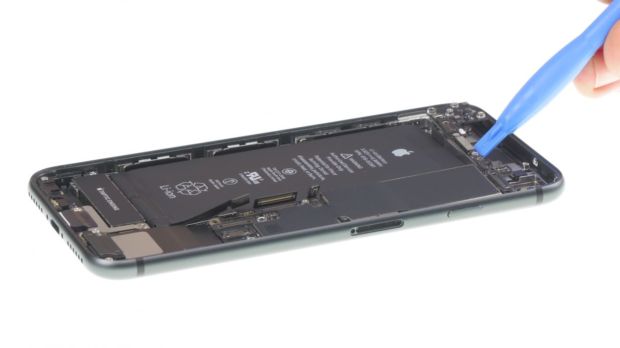
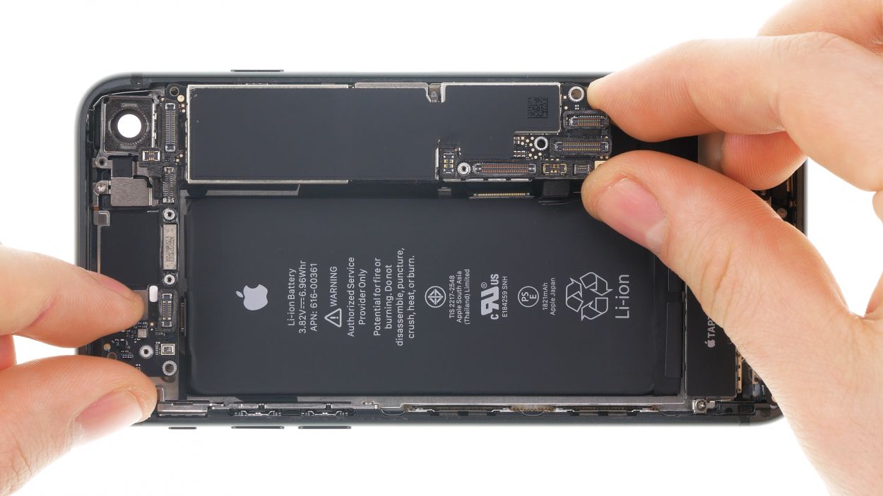
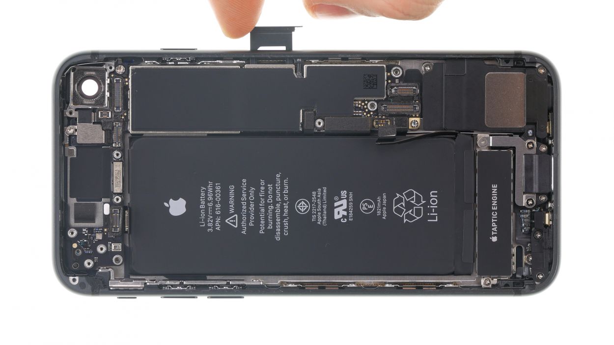
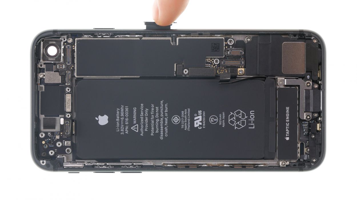
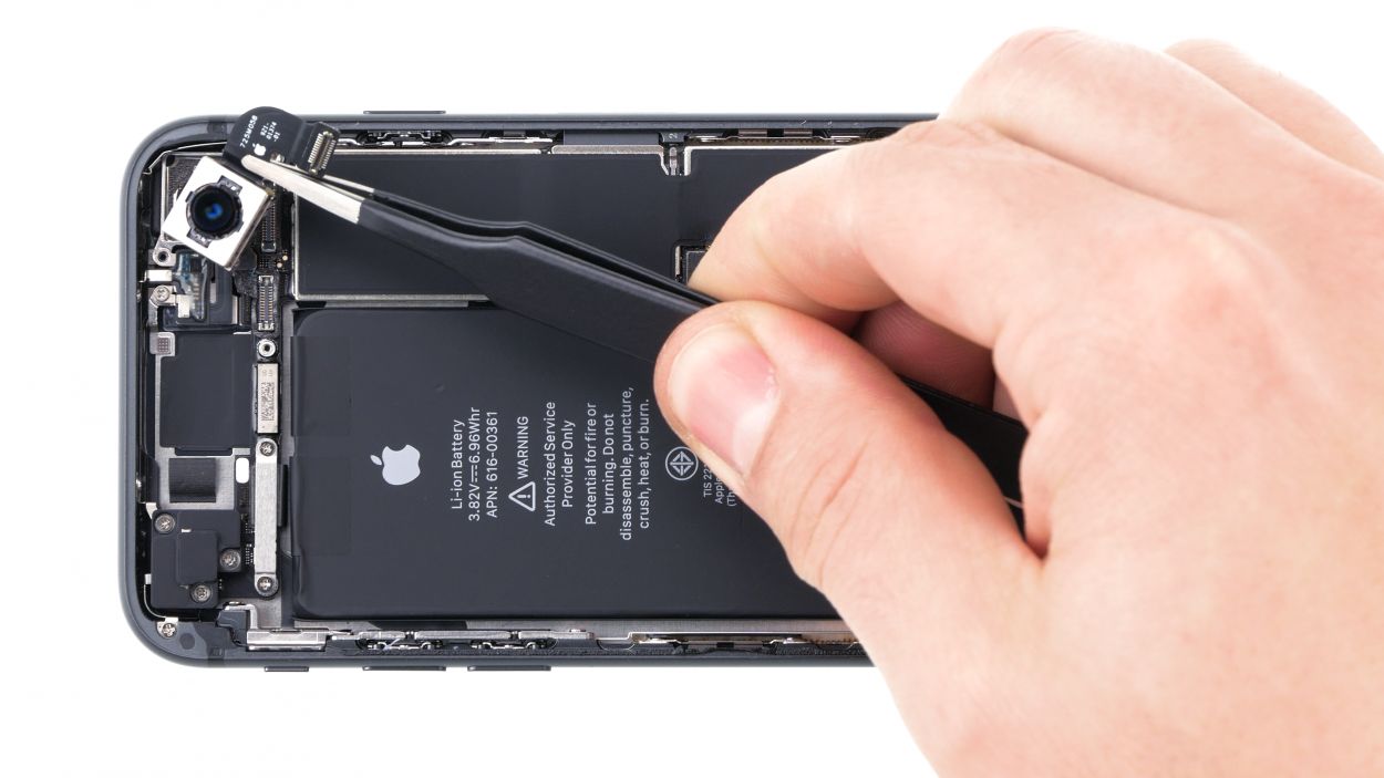
– First things first, let’s unscrew all those little screws holding the logic board in its cozy spot. You got this!
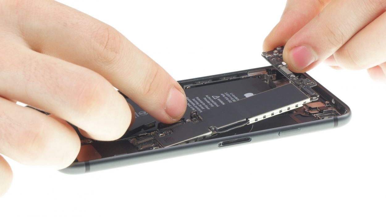
– Now, with a gentle touch, you can lift out the logic board by hand. Just a heads up—next to the two holes for the iSight camera, there’s a plastic holder for a screw sitting on top of the logic board. Easy peasy!
Step 16

1 × 1.2 mm Y-type
1 × 2.9 mm Phillips
1 × 2.5 mm Phillips
1 × 1.4 mm Phillips
1 × 2.1 mm Phillips
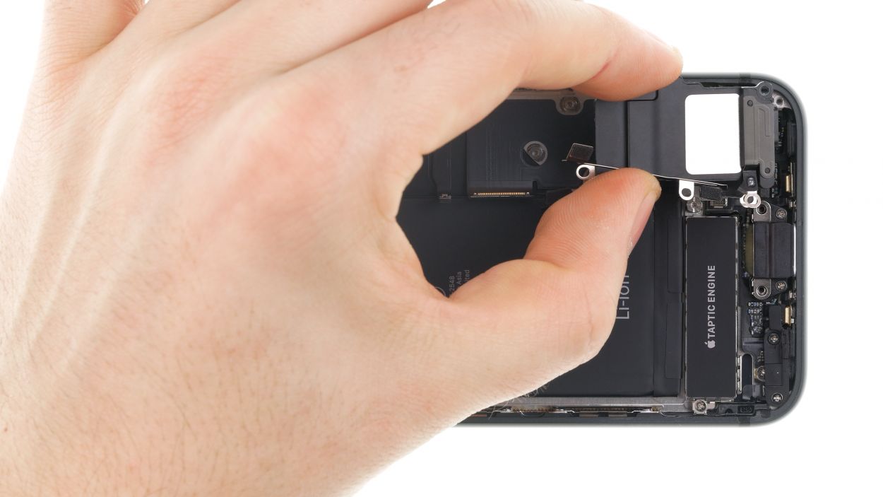
– First, let’s loosen those cover plate screws that are keeping the flex cable connector cozy. Once they’re free, set the plate aside like a pro!
– Now, gently disconnect the flex cable connector and lift it up with a smile.
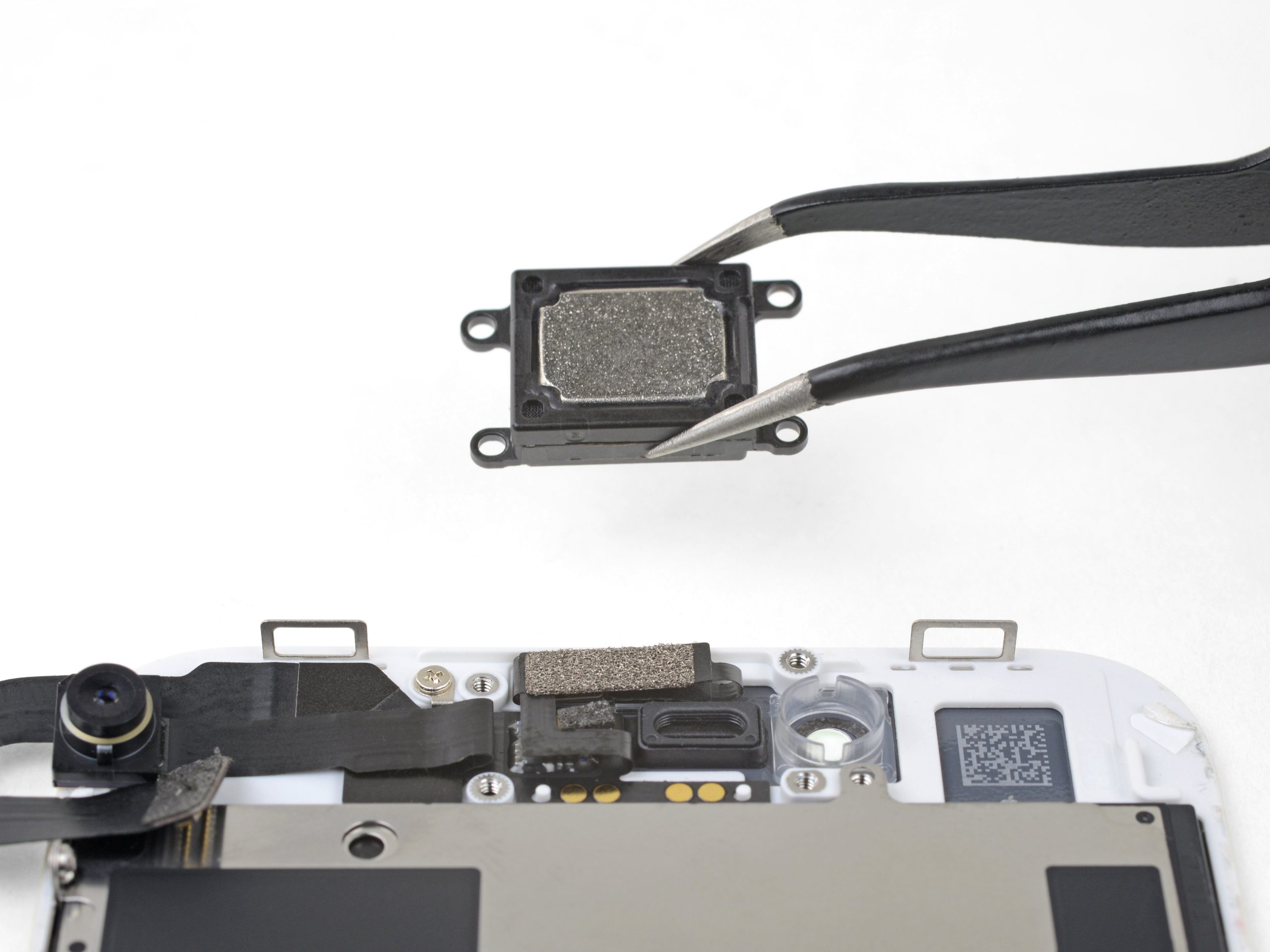
– Next up, loosen the screws of the speaker—you’re on a roll!
– With that done, you can now lift out the speaker along with the flex cable. You’re doing fantastic!
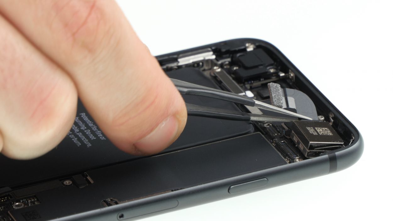
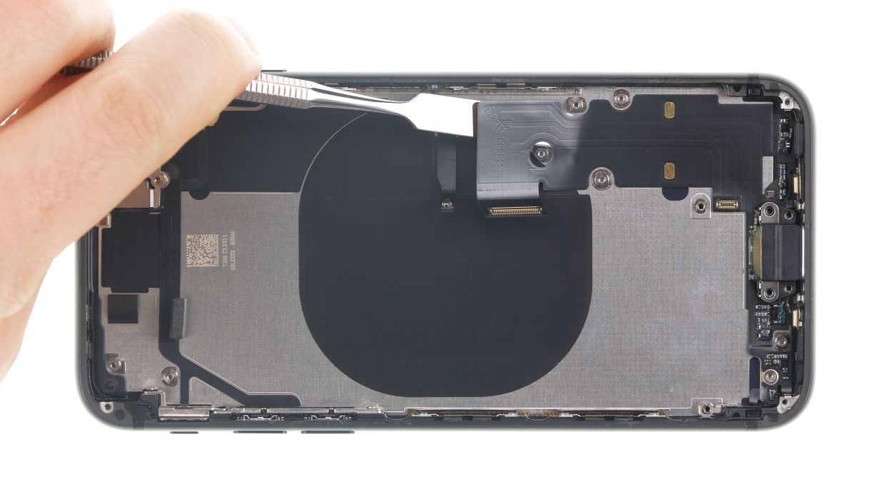
Step 17
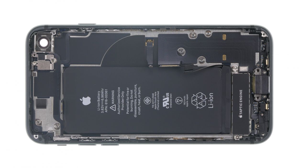
1 × 2.0 mm Standoff
1 × 2.0 mm Phillips
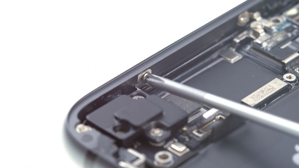
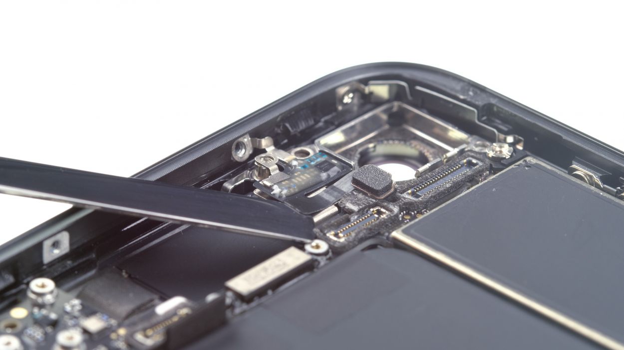
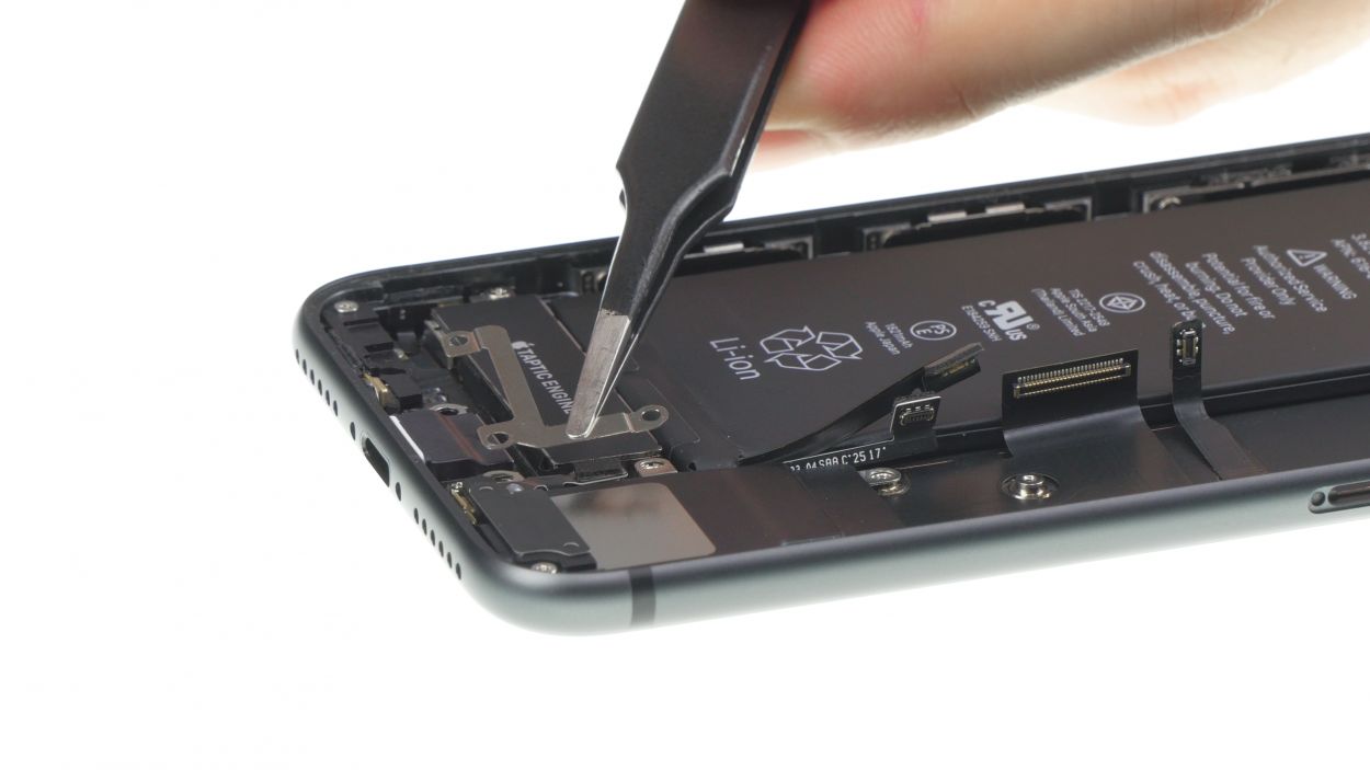
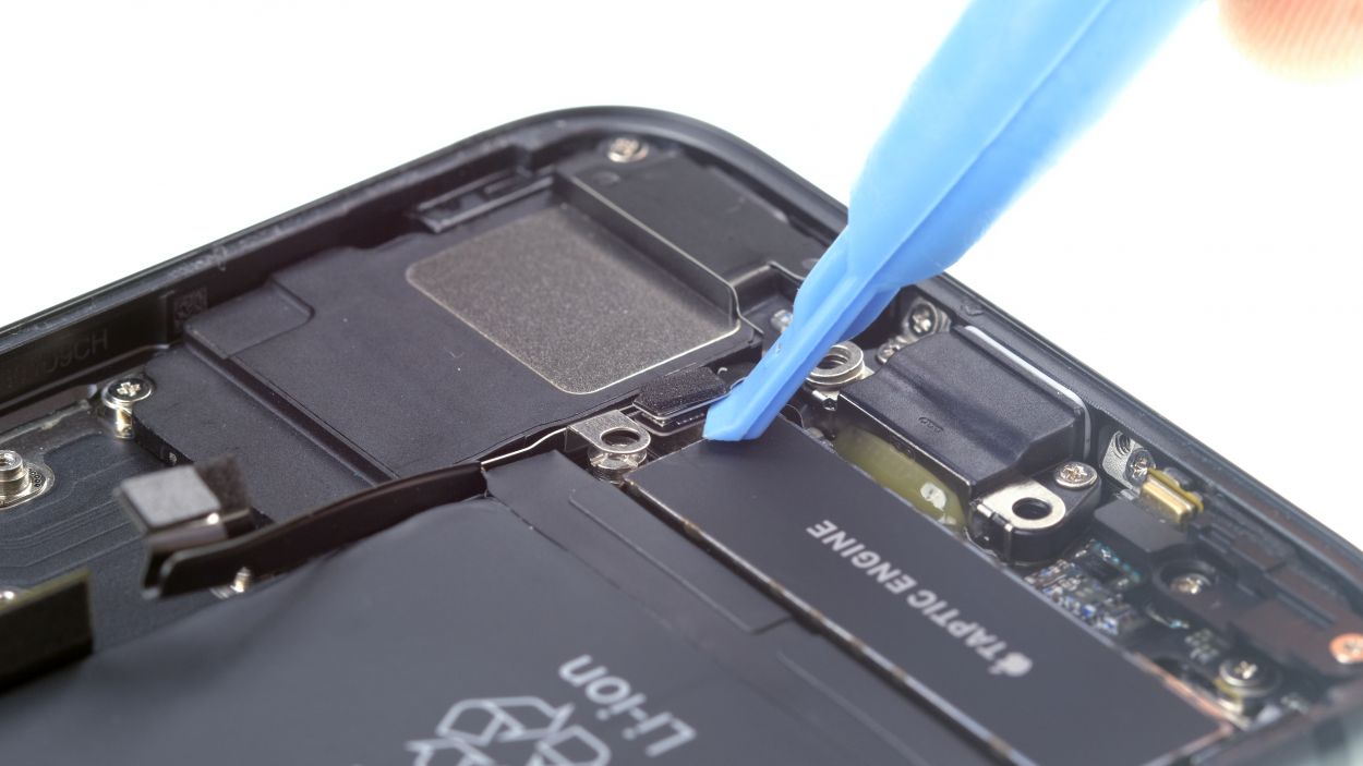
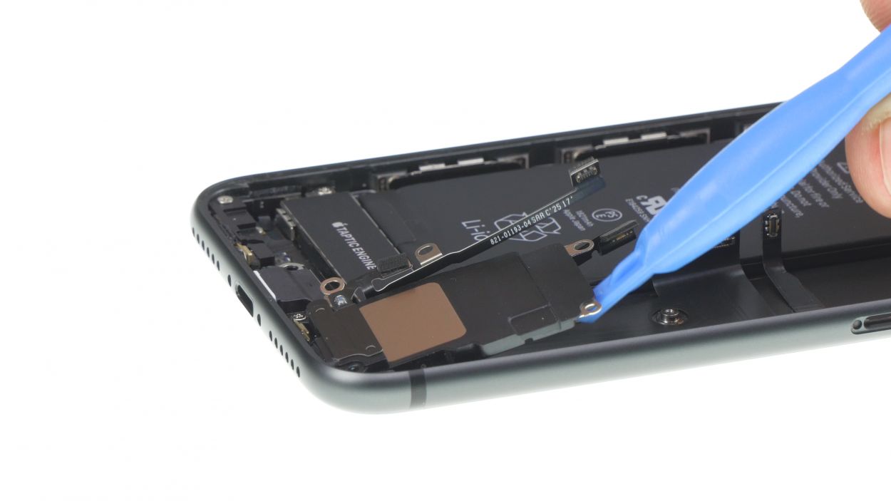
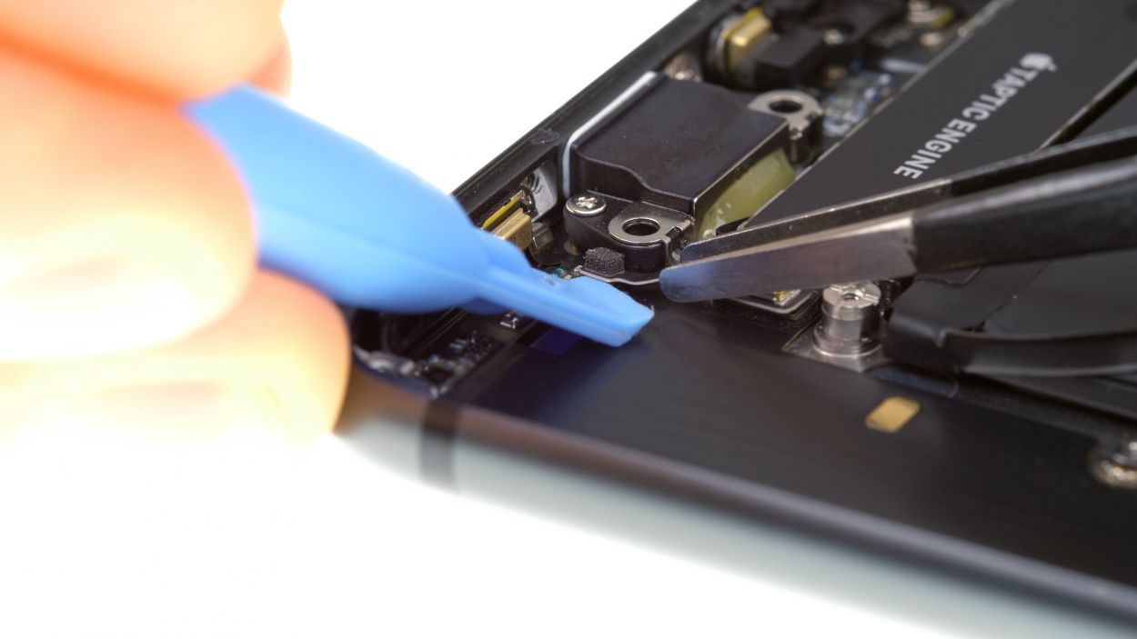
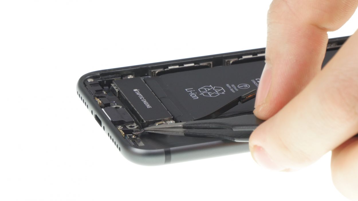
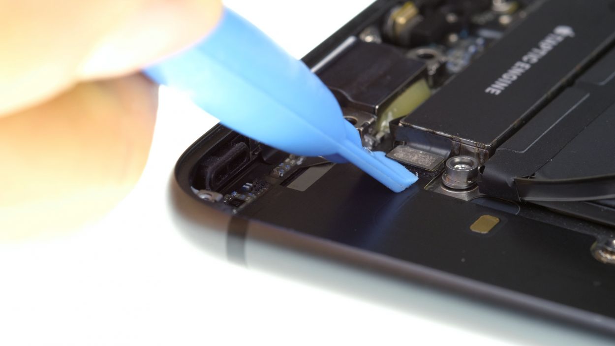
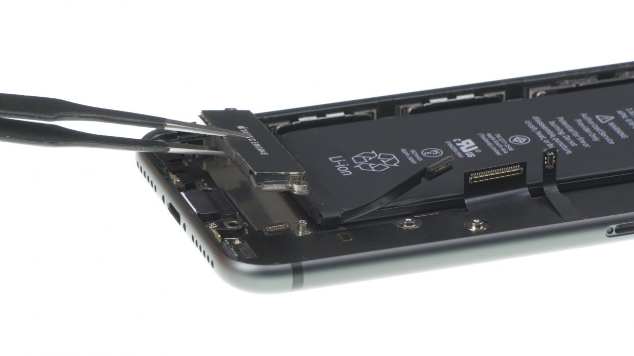
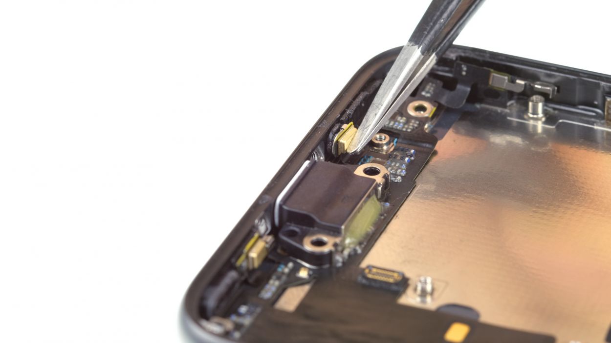
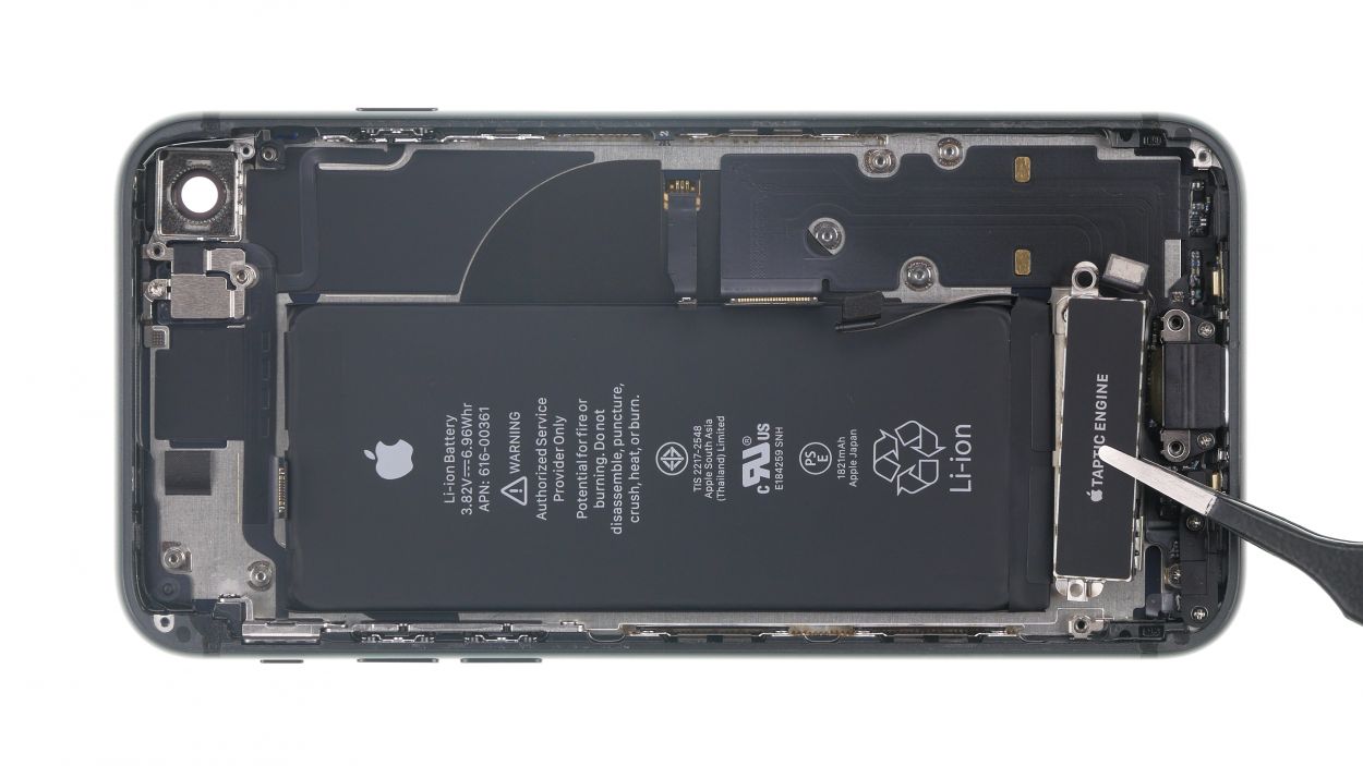
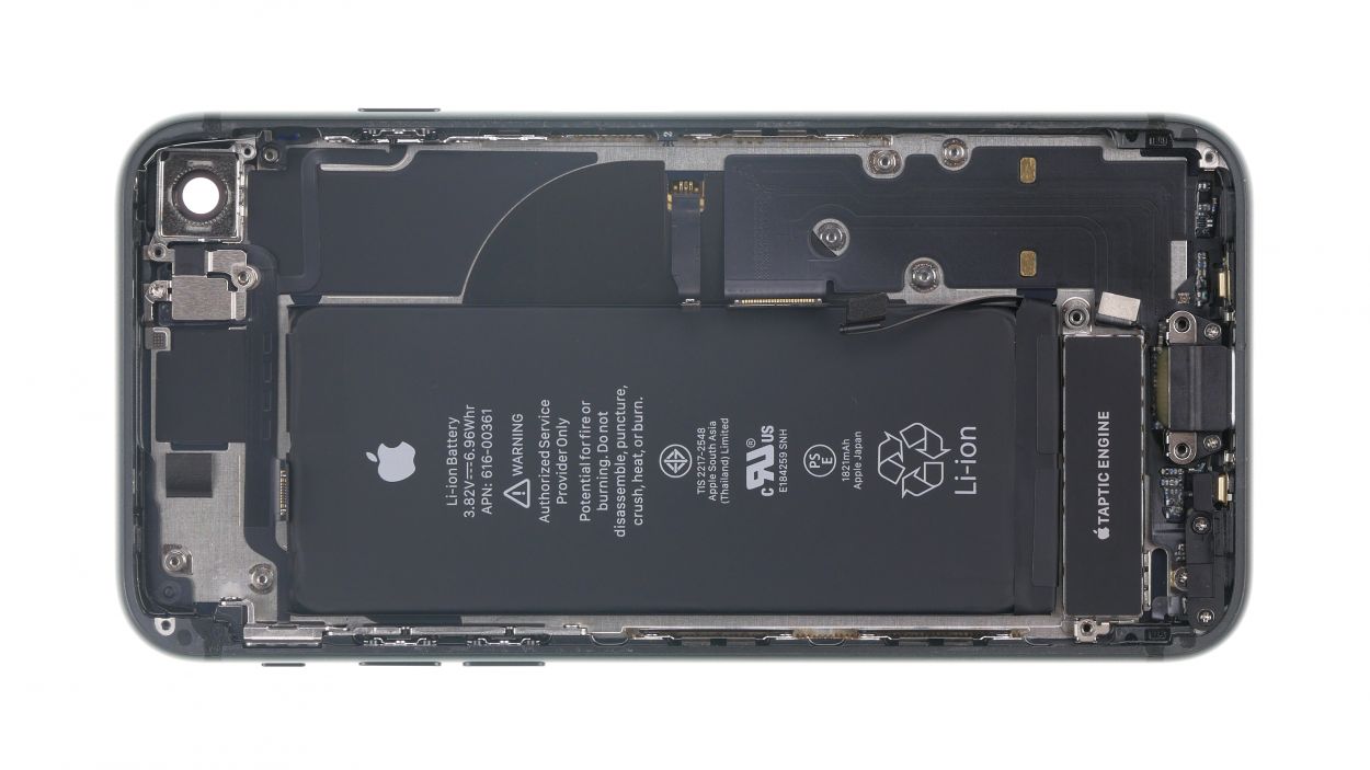
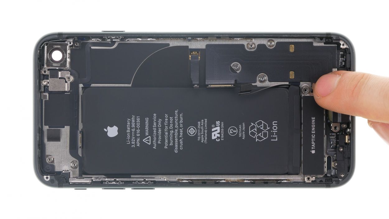
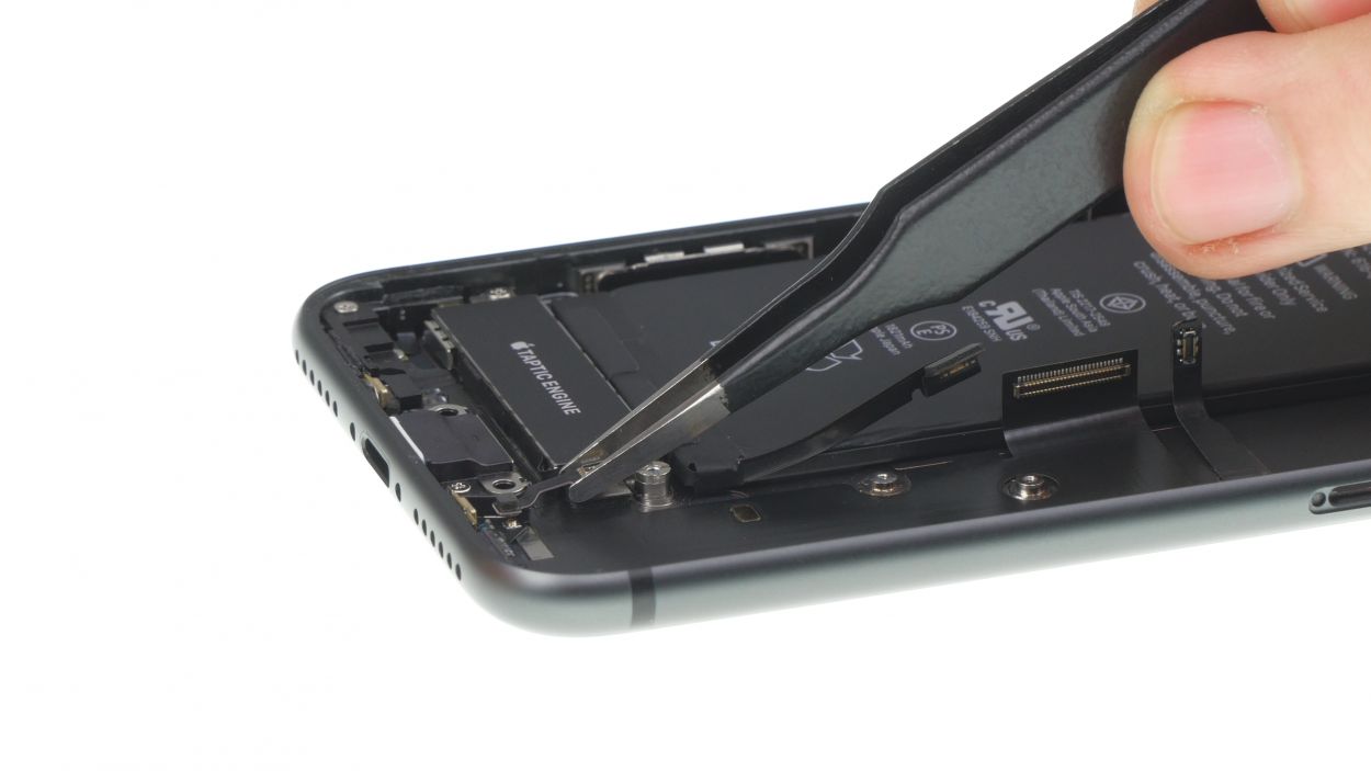
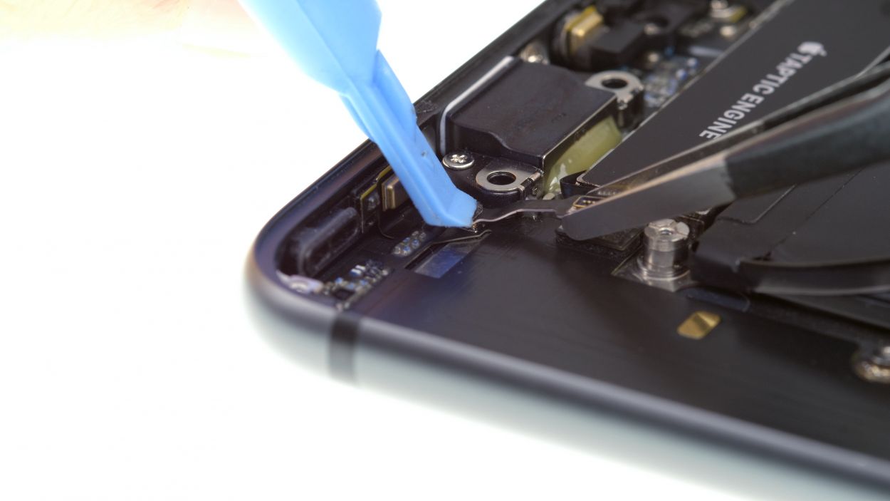
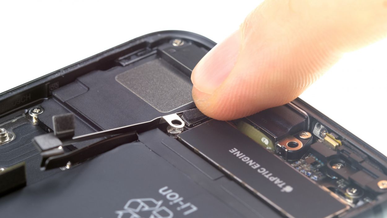
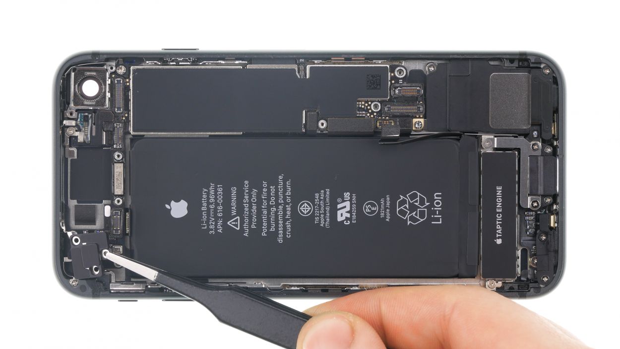
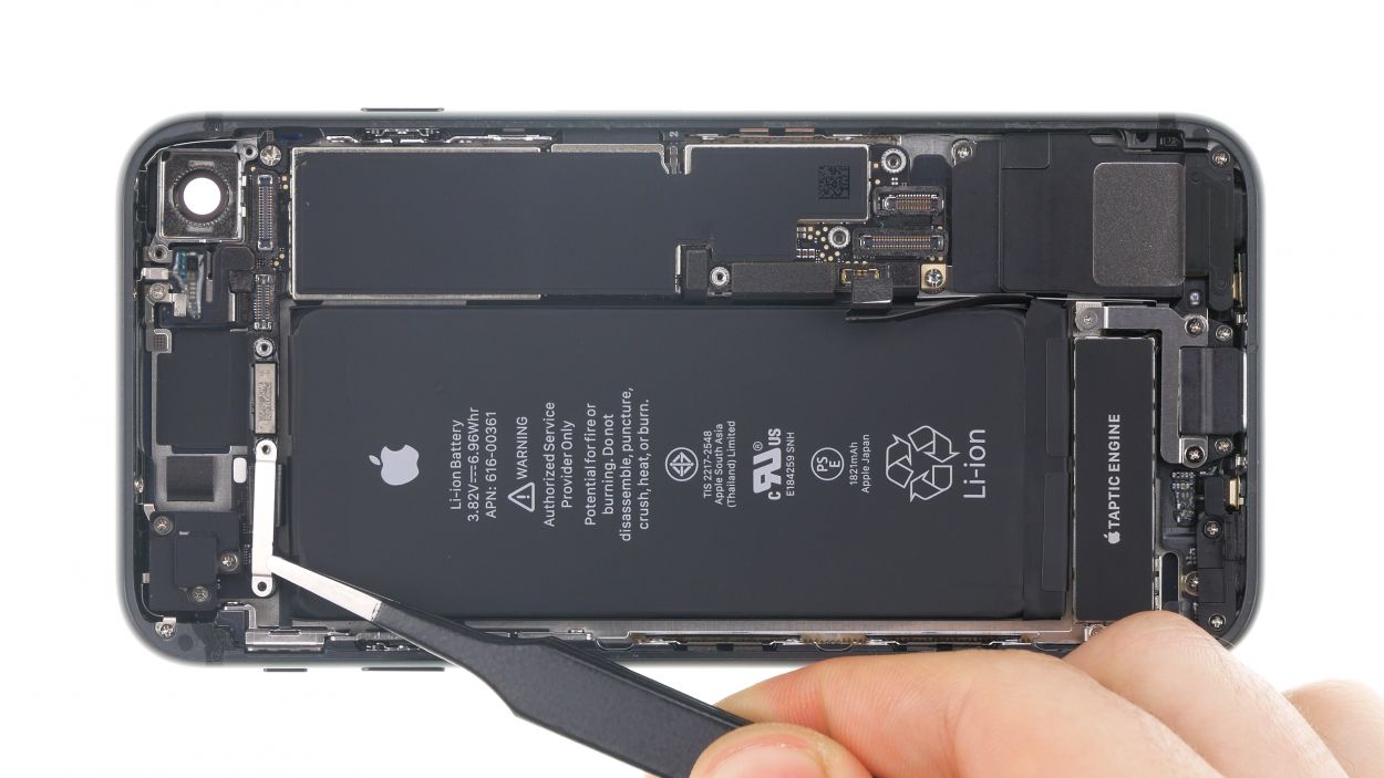
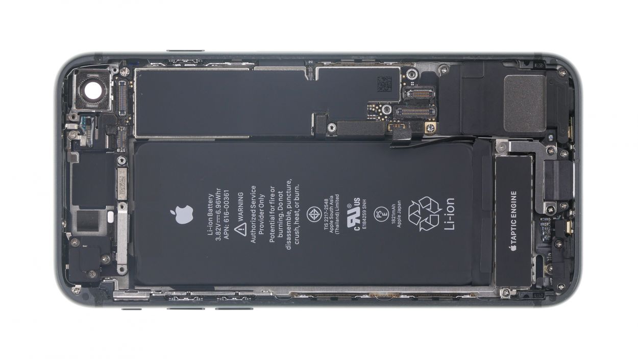
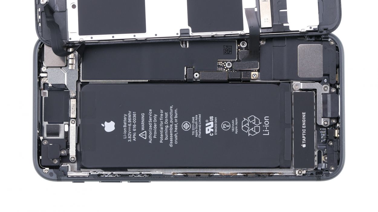
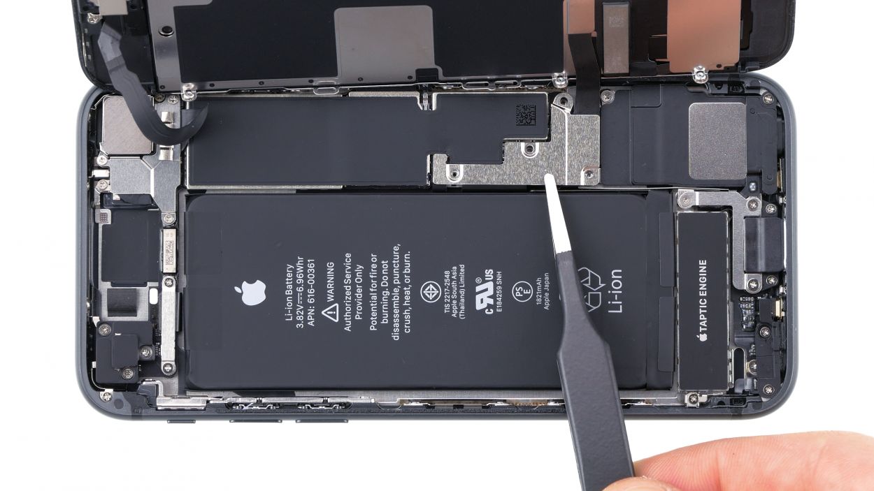
– First, let’s give that little flex cable above the Taptic Engine connector a gentle nudge with your trusty spudger or tweezers and detach it. You’re doing great!
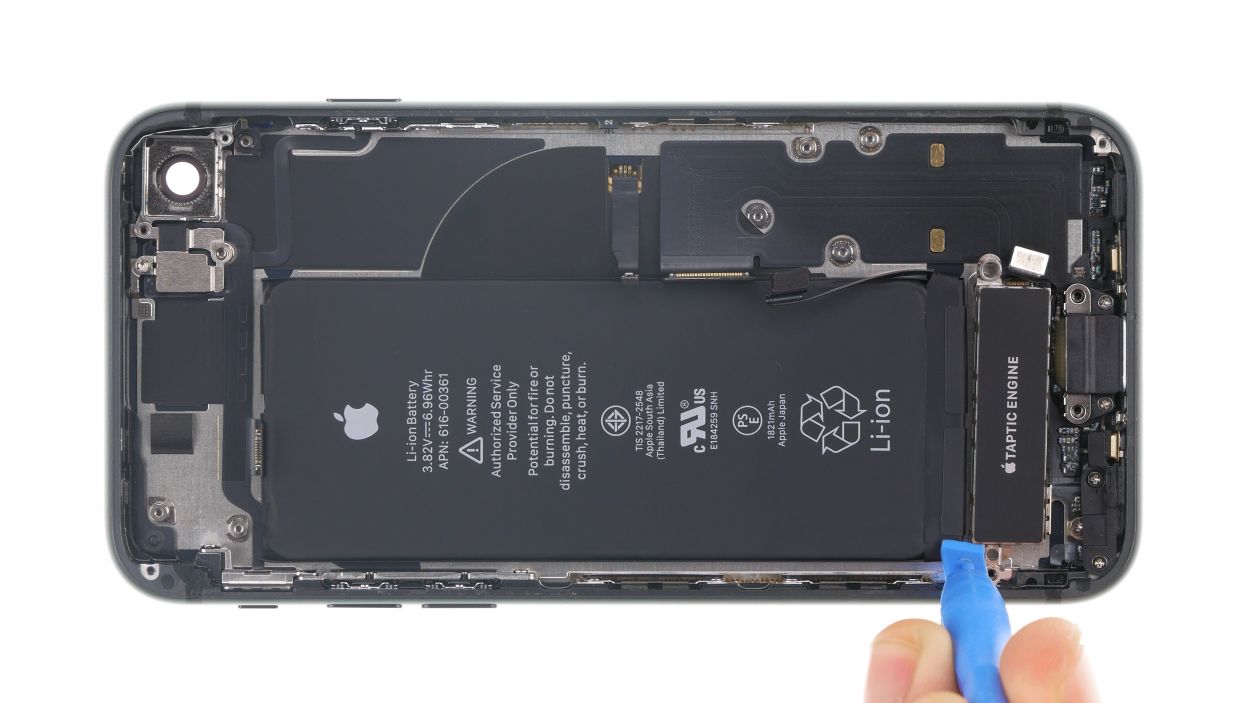
– Next up, loosen those screws that are keeping the Taptic Engine snug in its spot. You’re on a roll!
– Now, carefully use your spudger to pry up the Taptic Engine connector and lift that Taptic Engine out of your device. Nice job!
Step 19
1 × 1.7 mm Phillips
1 × 1.9 mm Phillips
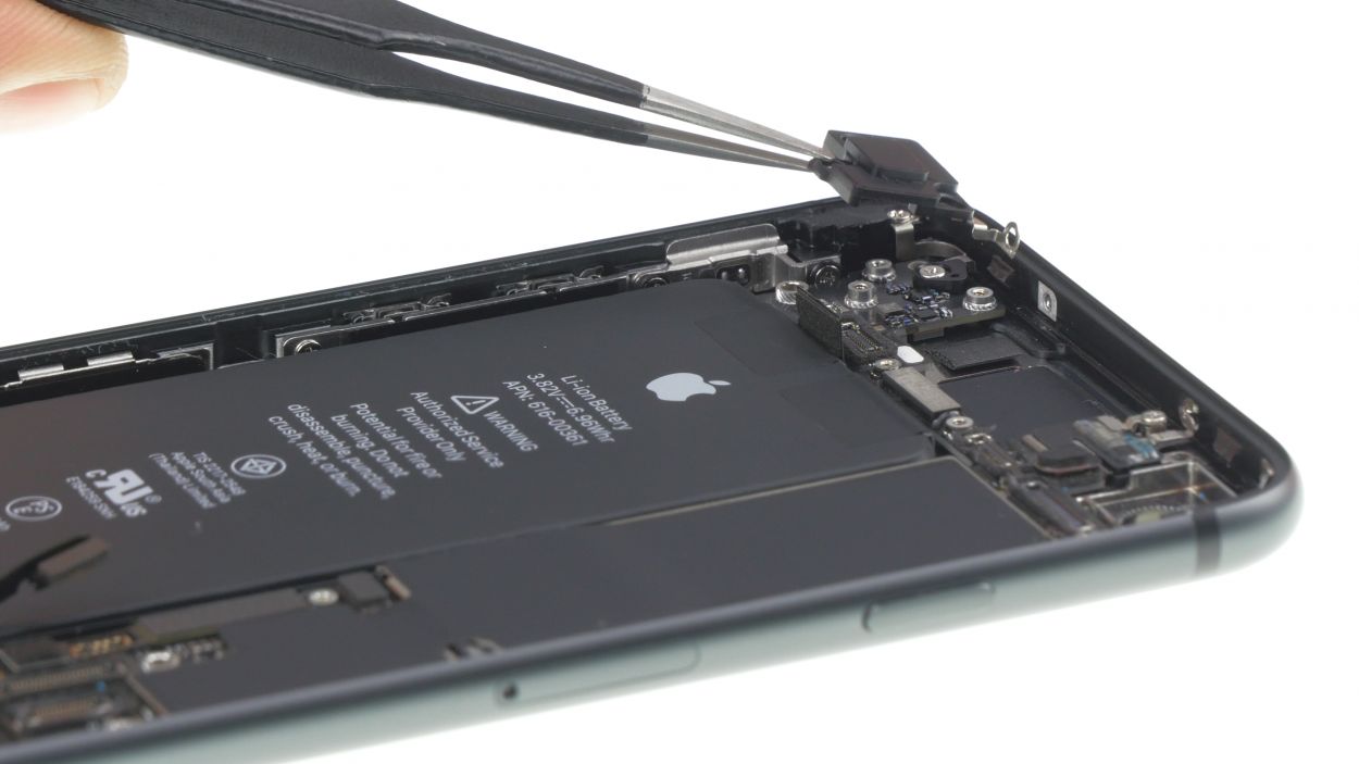
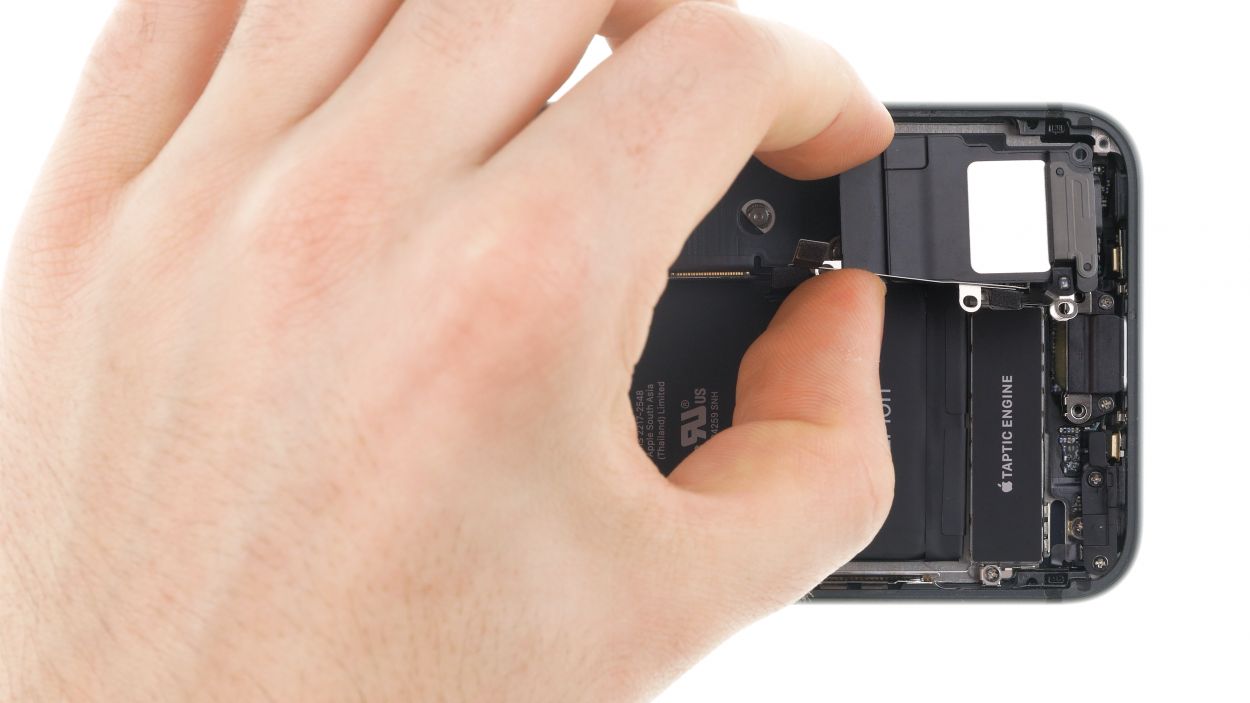
– Unscrew the two screws holding the barometric vent in place. You’re on the right track!
– Now, with a gentle touch, use your tweezers to carefully lift off the barometric vent. It’s got a little glue holding it, but you’ve got this!
Tools Used
Step 20

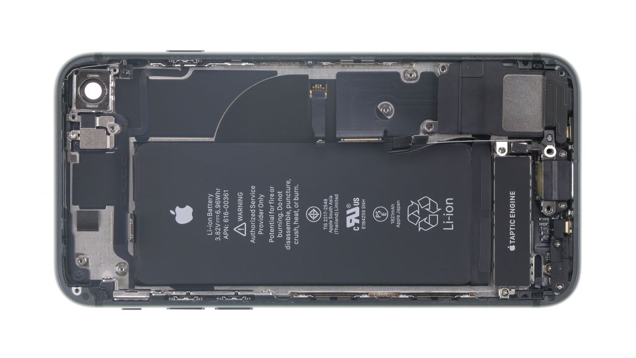
2 × 2.1 mm Phillips
3 × 1.2 mm Phillips
Those sneaky screws are having a little party under some black stickers along the edge of the housing! You’ll need to peel those back to get to them. Let’s get to it and show those screws who’s boss!
– Now it’s time to say goodbye to those Phillips screws! Give them a gentle twist and watch them come right out. You’re nailing this repair journey!
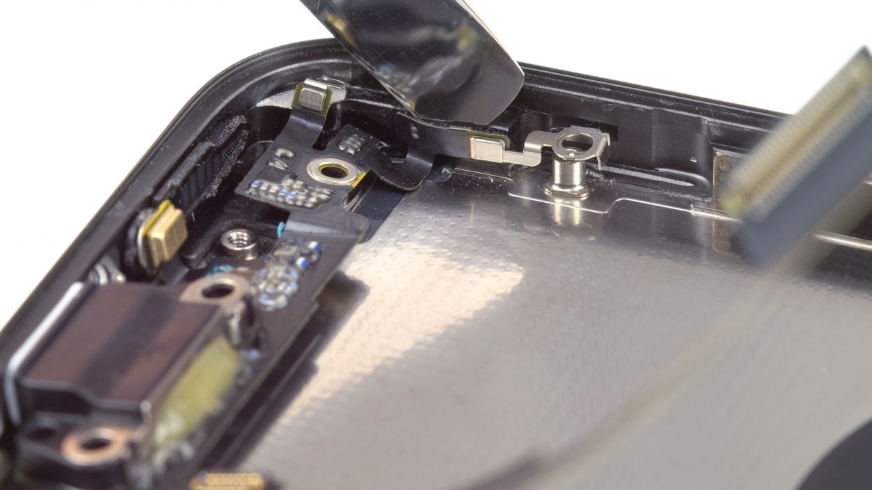
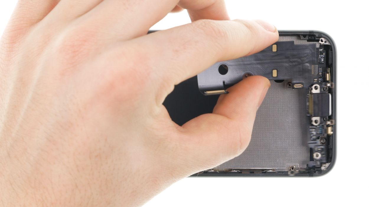
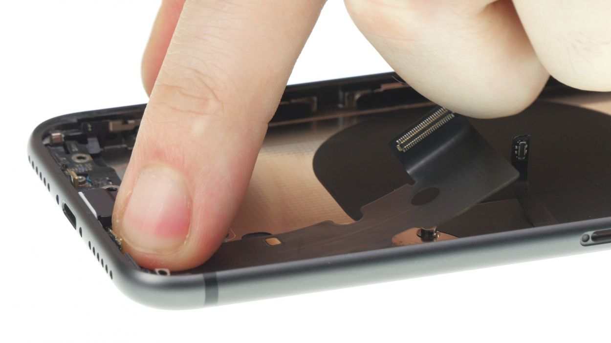
Step 21
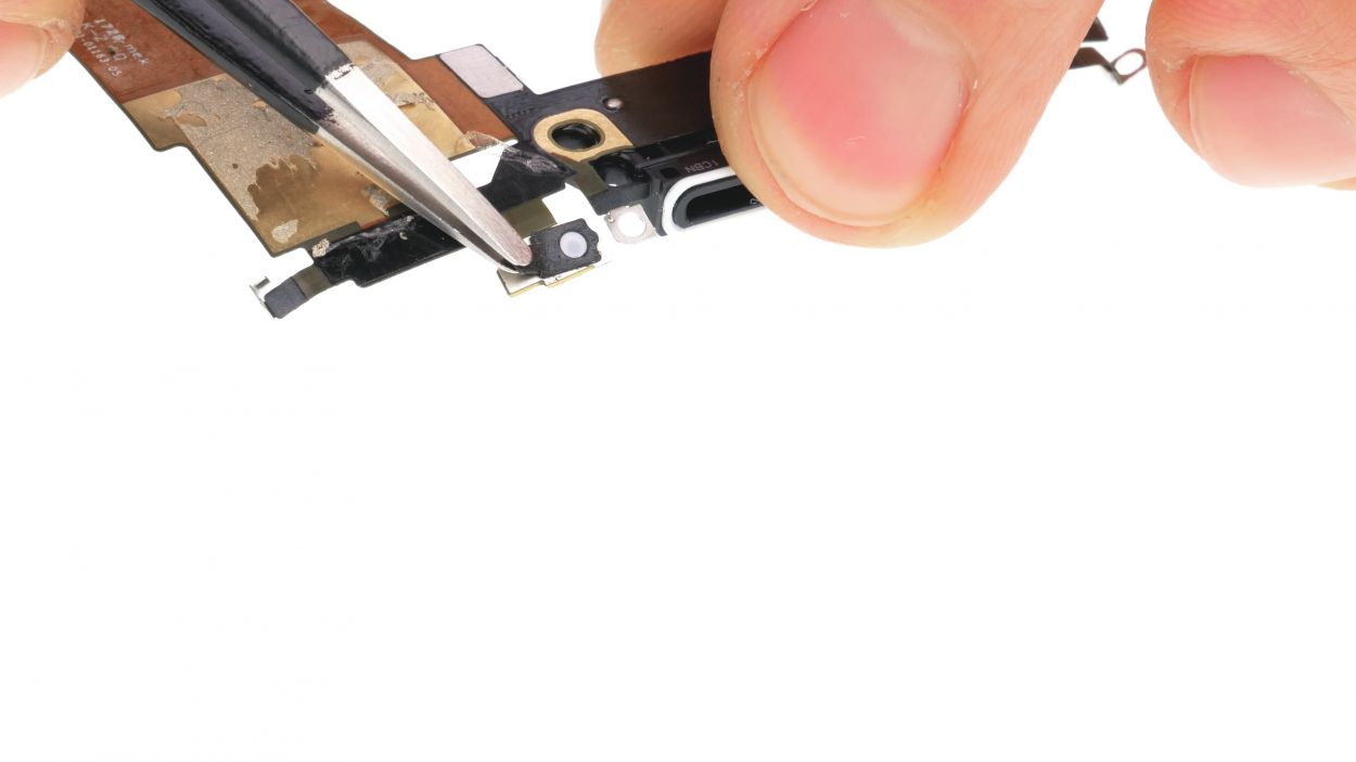
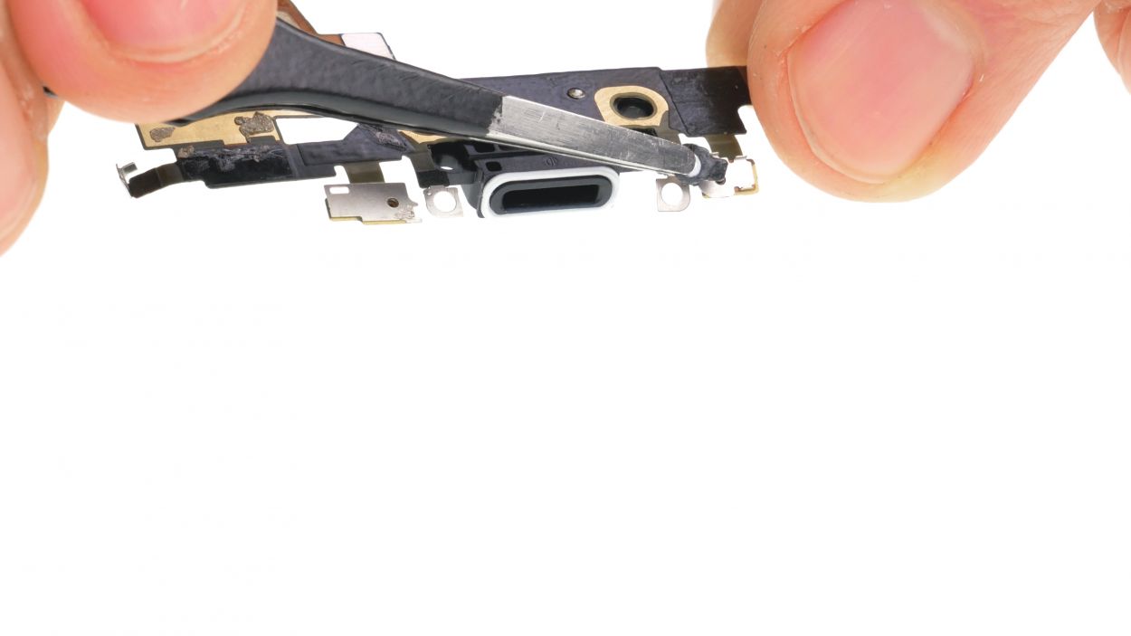
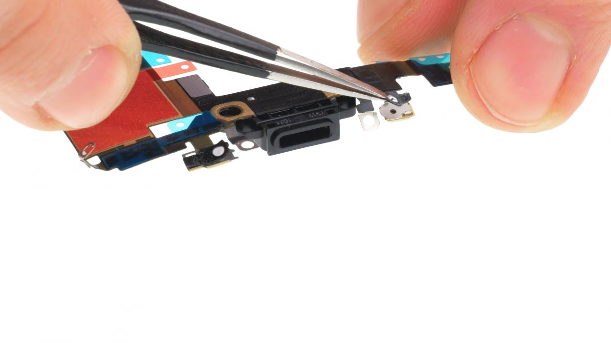
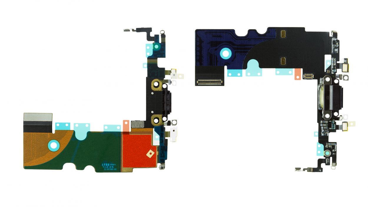
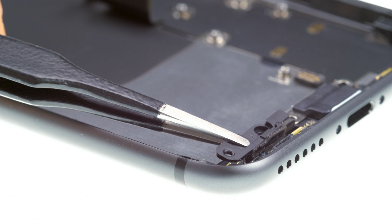
– Take those two rubber seals off the back of the microphones and give them a new home. They’ll help your microphones fit just right!
– Next, peel off the protective films from the adhesive surfaces on your shiny new Lightning connector. You’re on the right track!
Step 22
2 × 2.1 mm Phillips
3 × 1.2 mm Phillips
– Drücke das Flexkabel des Lightning Connectors sanft an seinen Platz auf dem Boden des Backcovers. Es sollte richtig schön flach sein!
– Presse die zwei Mikrofone, die am Flexkabel integriert sind, in ihre vorgesehenen Führungen am Rand des Backcovers. Sie haben dort ihren Platz gefunden!
– Fixiere nun den Lightning Connector, indem du alle zuvor gelösten Schrauben wieder anbringst. Du machst das super!
Step 23
1 × 1.7 mm Phillips
1 × 1.9 mm Phillips
– Put the barometric vent back in its place.
– Fasten it using the two screws.
Step 24
1 × 2.0 mm Standoff
1 × 2.0 mm Phillips
Double-check that the screw holes for the Taptic Engine are lined up just right! This little detail will keep those screws safe and sound, so no damage occurs. You’ve got this!
– Slide the Taptic Engine back in between the battery and the Lightning connector. You’re almost there!
Step 25

1 × 2.1 mm Phillips
1 × 1.4 mm Phillips
1 × 1.2 mm Y-type
1 × 2.9 mm Phillips
1 × 2.5 mm Phillips
Just a friendly reminder: make sure to get that flex cable snugly nestled between the battery and the speaker. You’re doing great!
– Pop that speaker back into its cozy spot in the rear case and give it a little press.
– Next up, secure the speaker with those two Phillips screws—you’re on a roll!
– Now, connect the speaker’s connector—just a gentle press will do the trick.
– Finally, place the bracket plate over the flex cable and fasten it down with the three screws. You’re almost done!
Step 26
1 × 2.4 mm Standoff
1 × 2.1 mm Standoff
1 × 1.6 mm Phillips
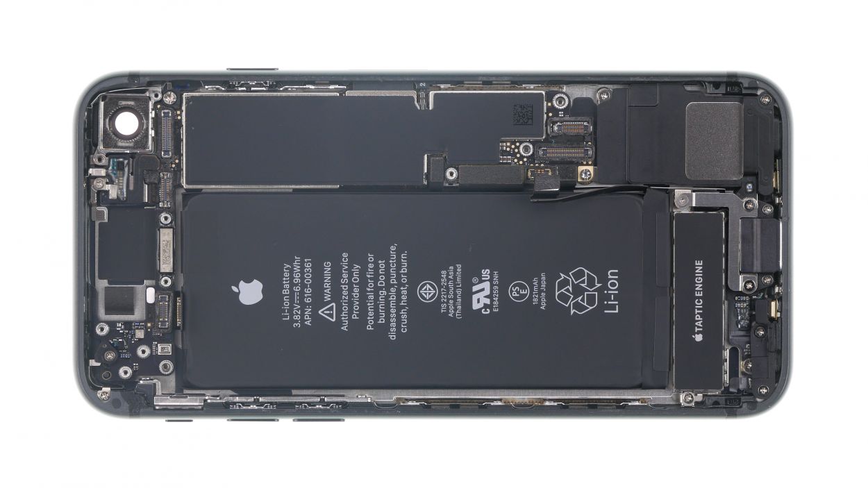
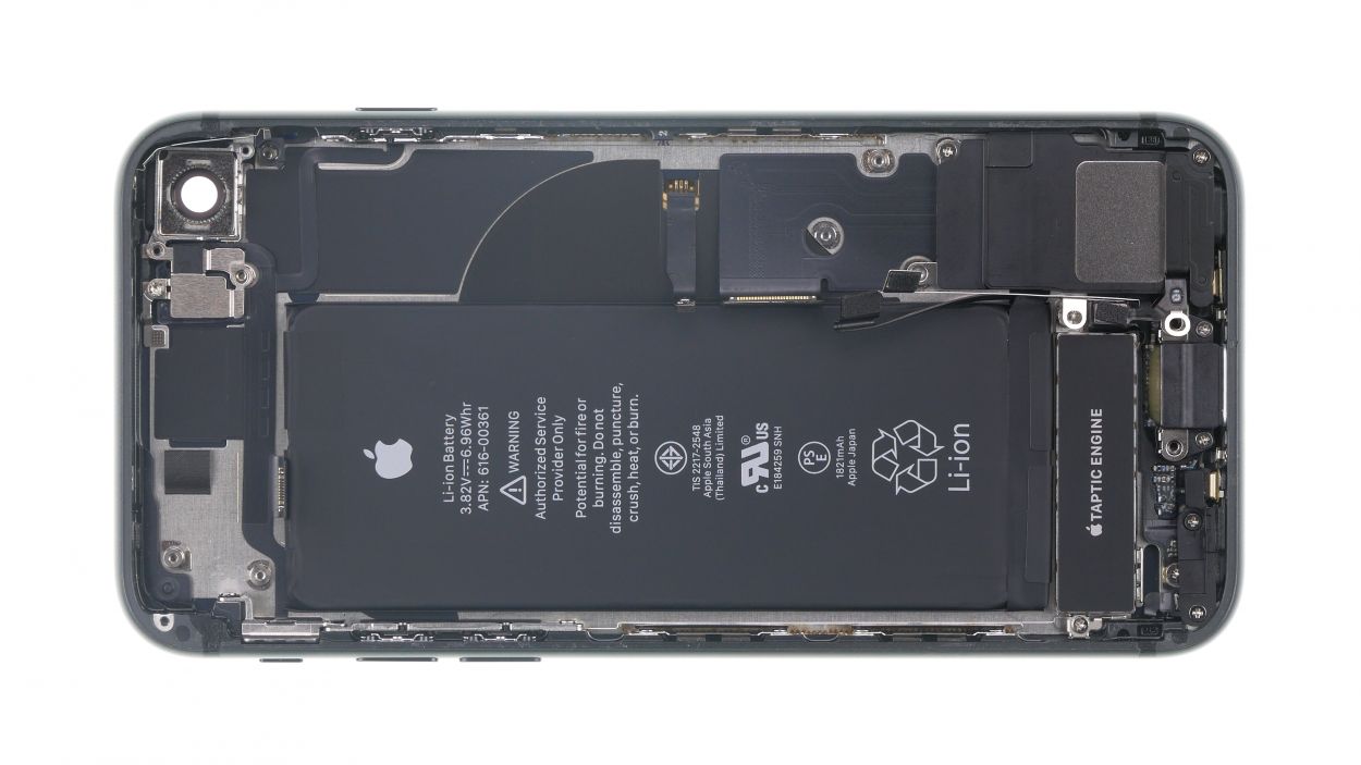
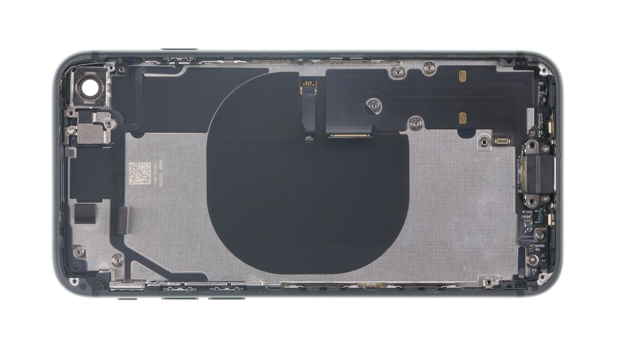
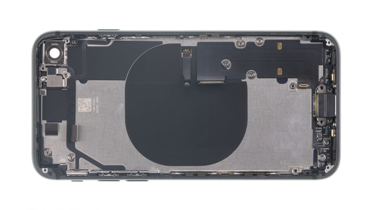
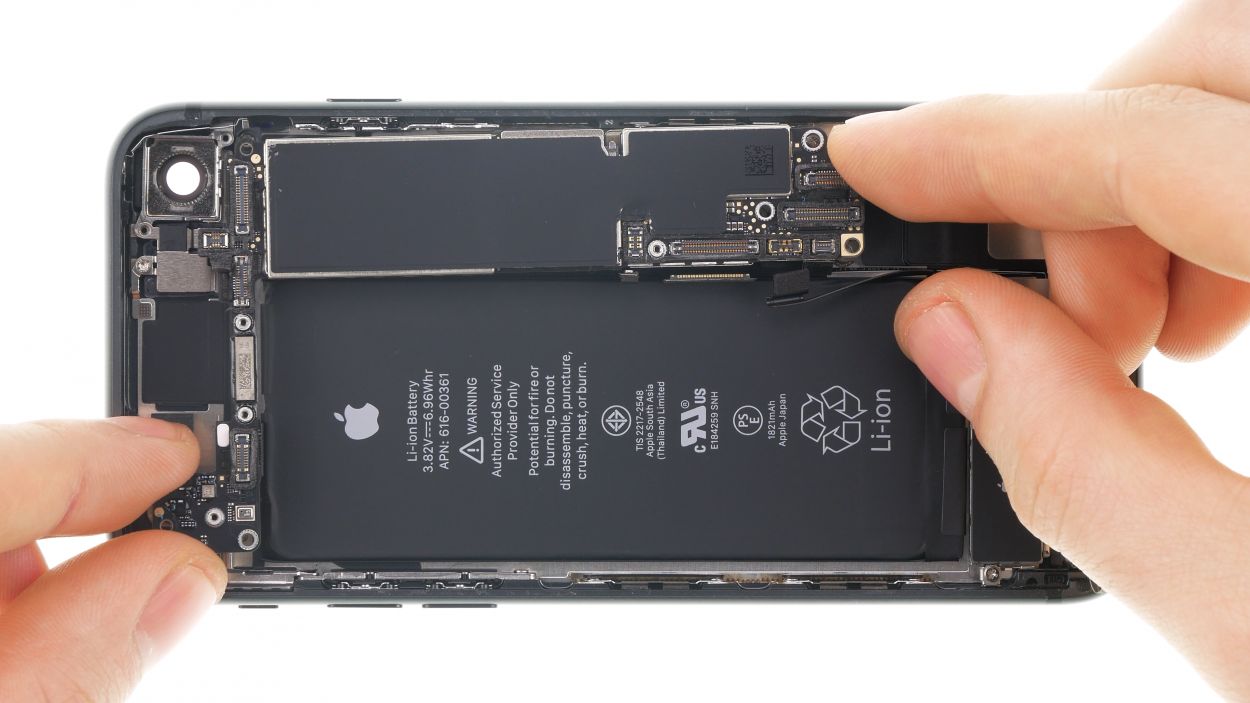
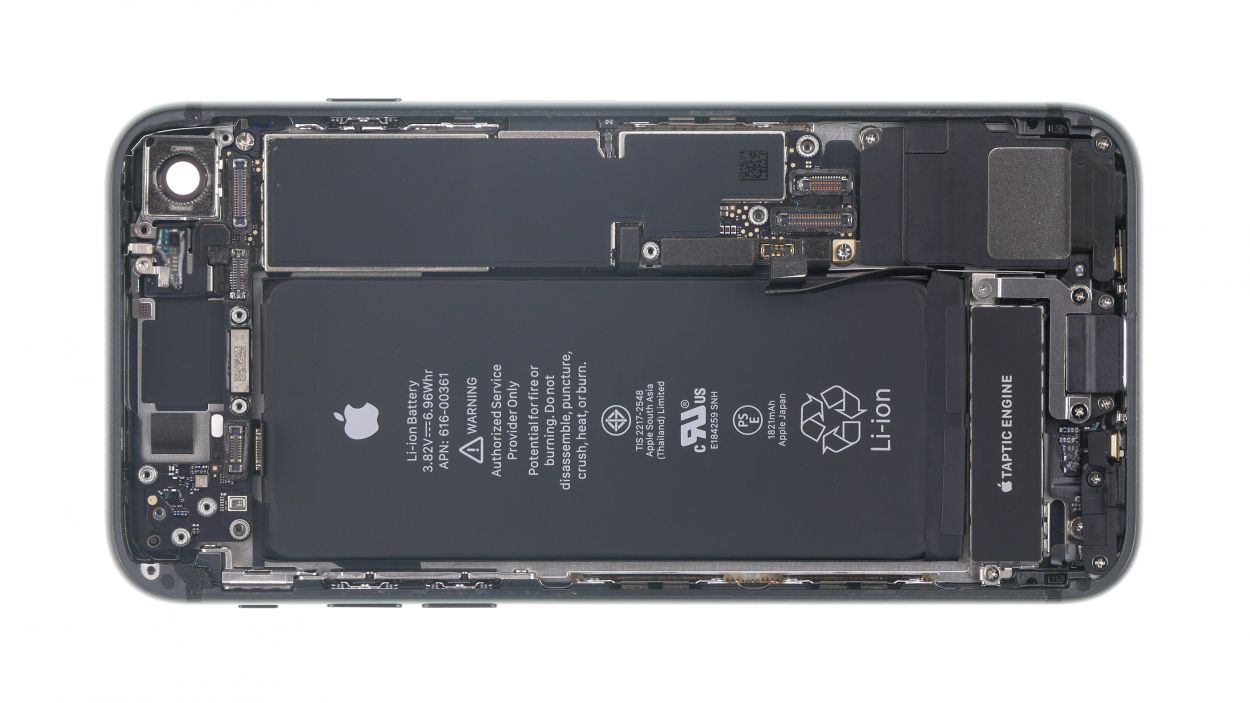
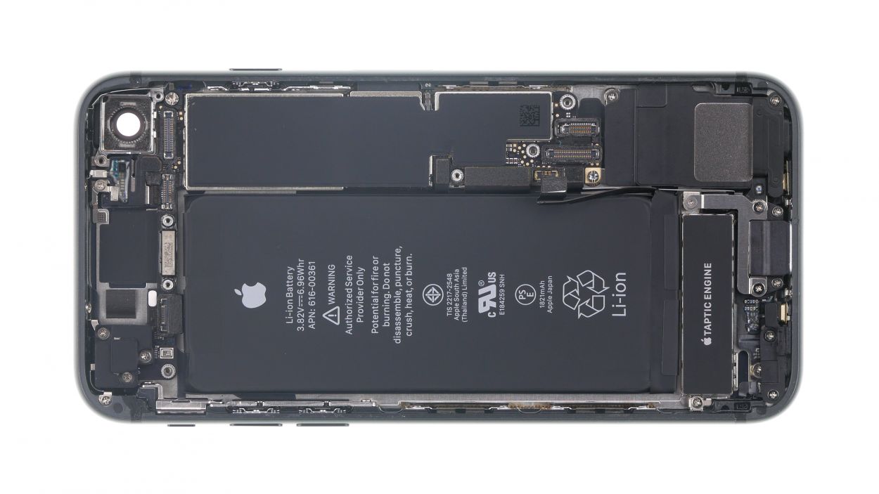
The camera holder is hanging out right on top of the logic board, just chillin’ over the screw hole in the top right corner of the image. Make sure it’s in the right spot before you move on!
– Carefully place the logic board back into its original spot, just like tucking in a cozy blanket!
Step 27
– First, align those connectors over their cozy little sockets and give them a gentle press with your finger. You’re doing awesome!
Step 28
If you’re finding it a bit tricky to slide that in, take a moment to check the position of the logic board. A little adjustment might just do the trick!
– Now, let’s slide that SIM card tray back into its cozy little slot. It should fit right in like it never left!
Step 29

1 × 1.3 mm Phillips
1 × 1.2 mm Phillips
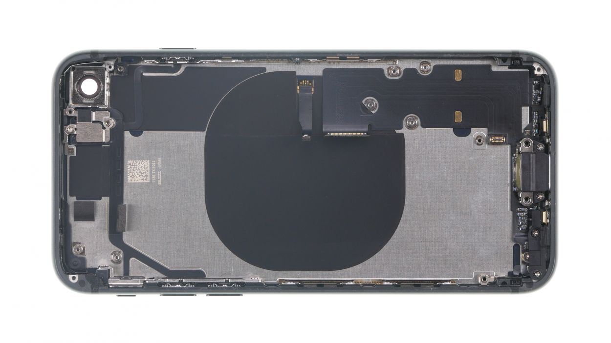
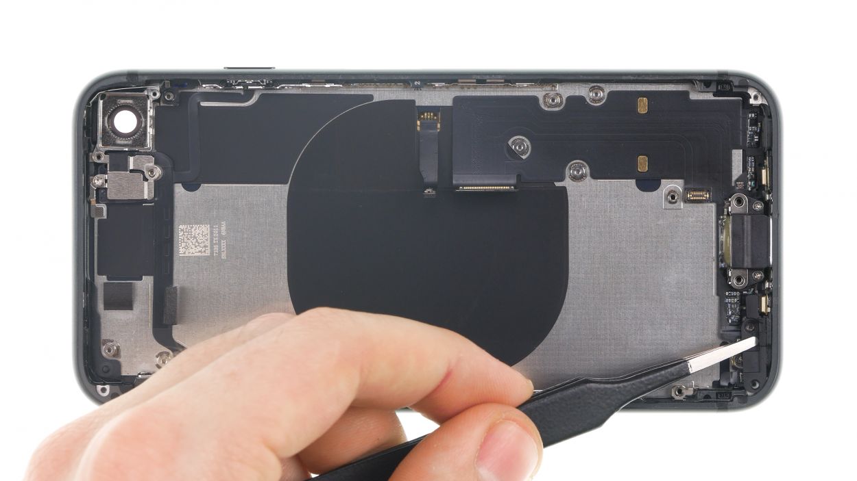
– Reposition the Wi-Fi antenna to its original home and give it a gentle press to make sure it sticks like it should!
– Next, connect the antenna’s connector with care.
– Finally, secure the bracket plate using those two Phillips screws. You’re doing great!
Step 30
1 × 2.5 mm Phillips
1 × 1.4 mm Phillips
2 × 1.2 mm Phillips
2 × 1.0 mm Phillips
– Pop that connecting piece back into place and give it a snug fit with those Phillips screws. You’re doing great!
– Next up, let’s reinstall that plastic bracket and secure it with Phillips screws too. You’re almost there!
Step 31
1 × 2.9 mm Phillips
1 × 3.0 mm Standoff
– Gently pop the camera back into its cozy home.
– Reconnect the camera connector with care.
– Place the camera’s bracket plate back on and give it a good twist to secure it tight.
Step 32
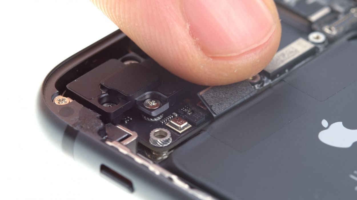
1 × 1.1 mm Phillips
1 × 2.7 mm Phillips
– Reconnect that volume control cable like a pro!
– Place the bracket plate back on the connector and secure it with those trusty screws.
Step 33
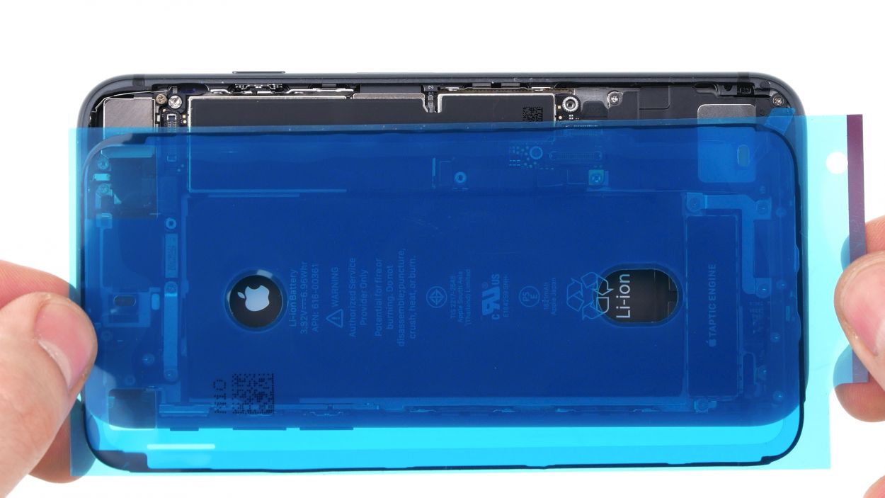
Once you attach that shiny new adhesive frame, your iPhone 8 will be back to fending off dust and splashes like a champ! Just remember, it’s not quite the same as being 100% waterproof anymore.
The corners are unique and serve as your trusty guide to keep everything oriented just right!
– First, let’s make sure that all that sticky adhesive residue is gone from the metal frame and display. This way, your new adhesive frame will fit like a glove!
– Now, give it a go by aligning that adhesive frame with the back cover of your iPhone. You want to get it just right for a perfect fit!
Tools Used
Step 34
3 × 1,0 mm Phillips-Schraube
– Stand the display up on the frame and connect that FaceTime connector to the logic board like a champ!
– Gently lay the display down next to the back cover, making sure it’s all cozy and ready for the next step.
– Cover that FaceTime connector with the plate and secure it in place using the three Phillips screws. You’re doing awesome!
Step 35
– Reconnect those two display connectors (the one for the display and the home button) to the logic board. You’re almost there!

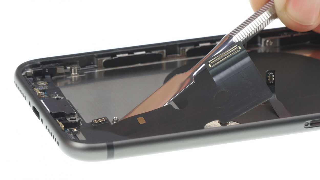
Step 37
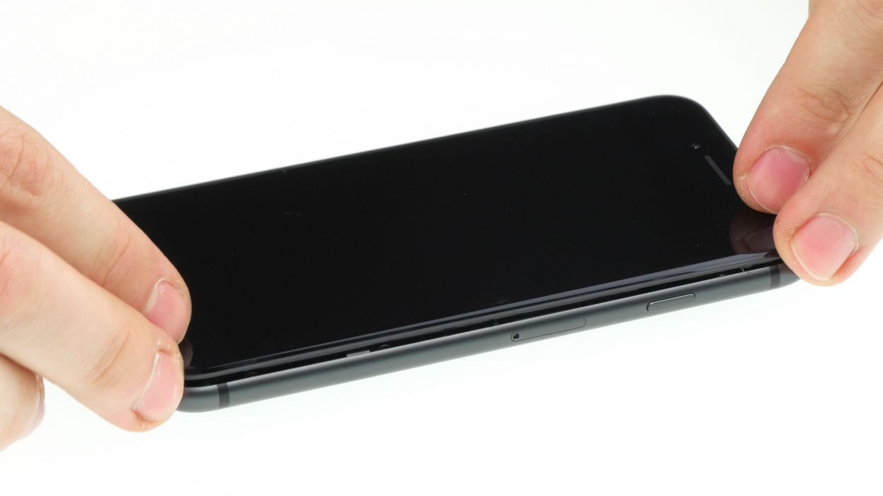
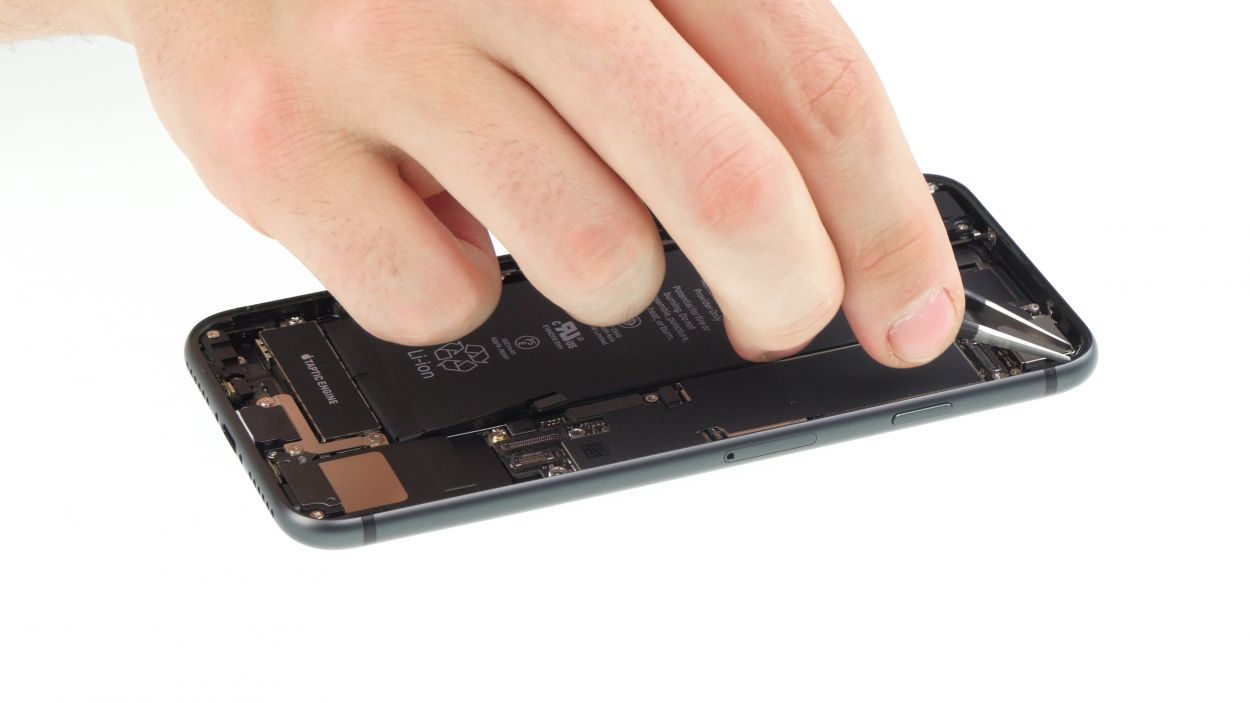
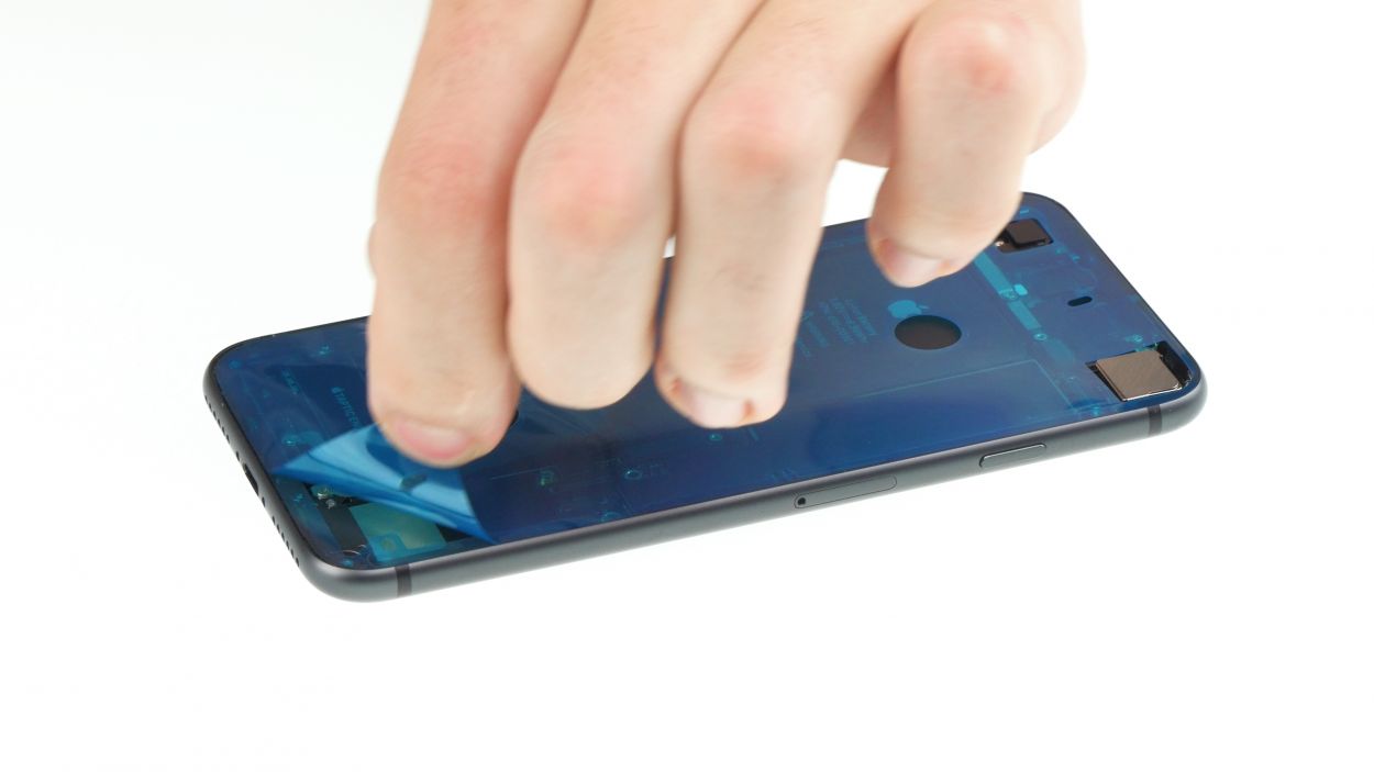
– Gently set the display next to the back cover and fold it over with care. It’s like tucking in a blanket!
– Now, give that display a firm press all over to make sure it sticks like a champ!
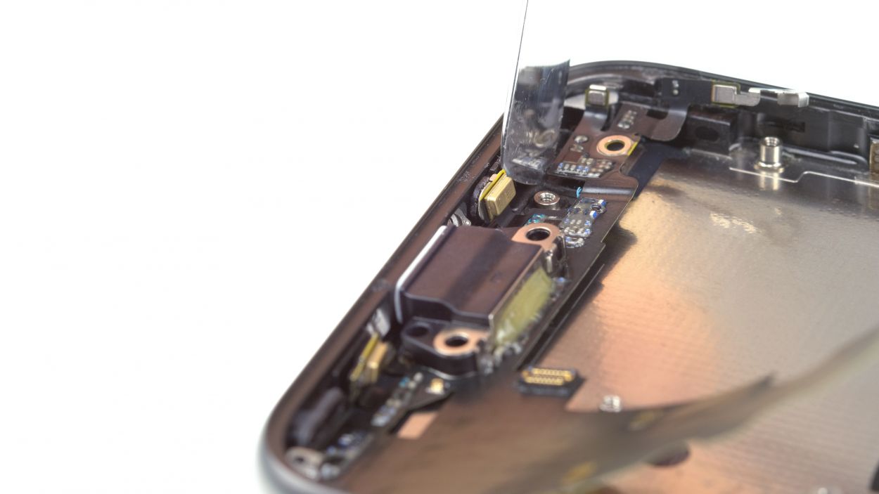
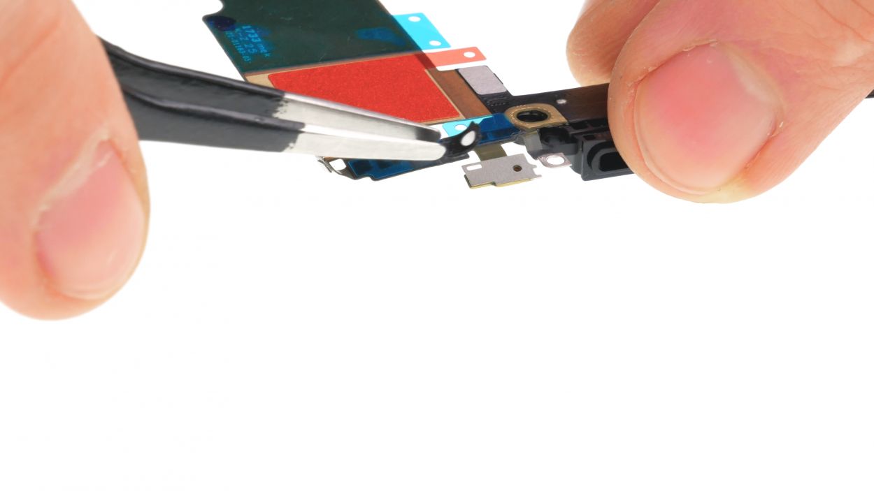
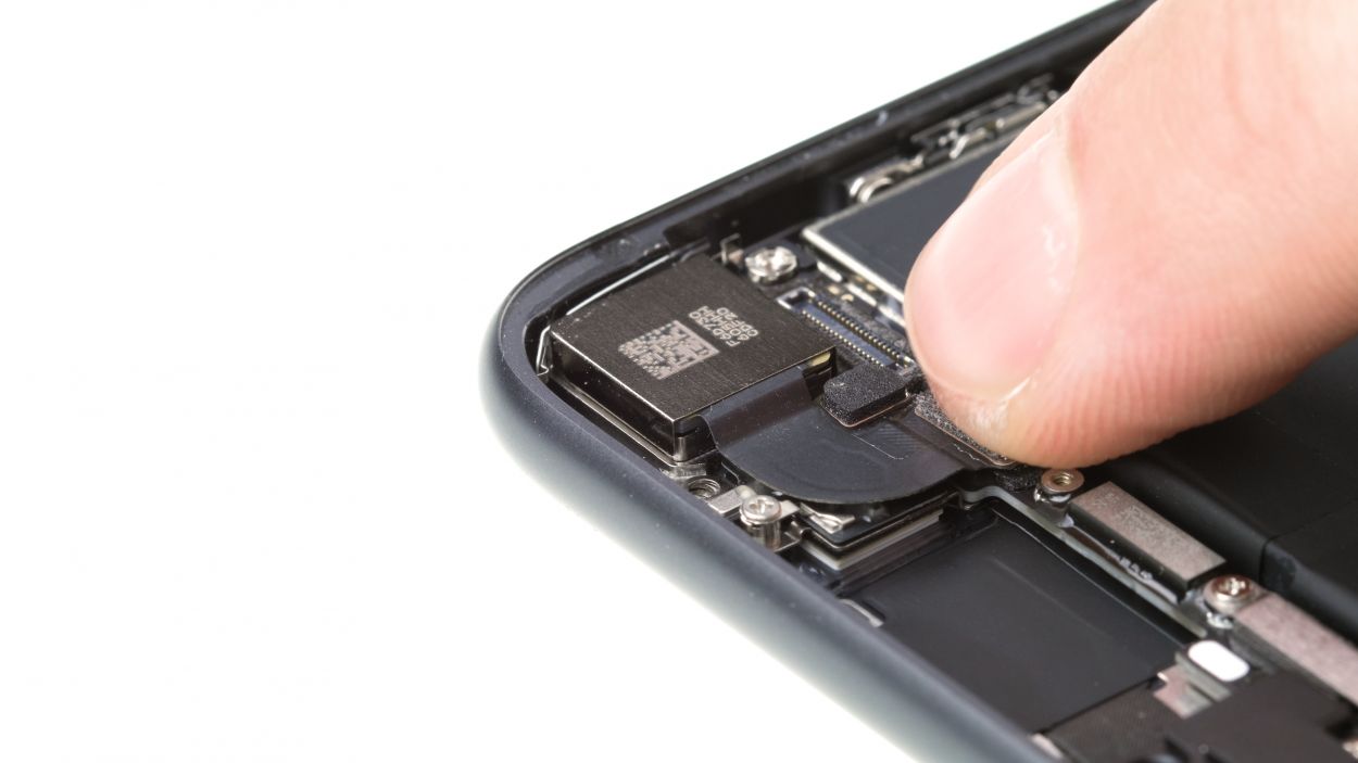
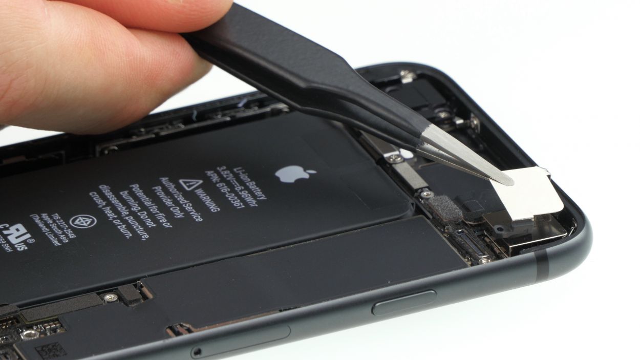
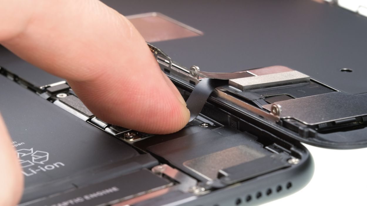
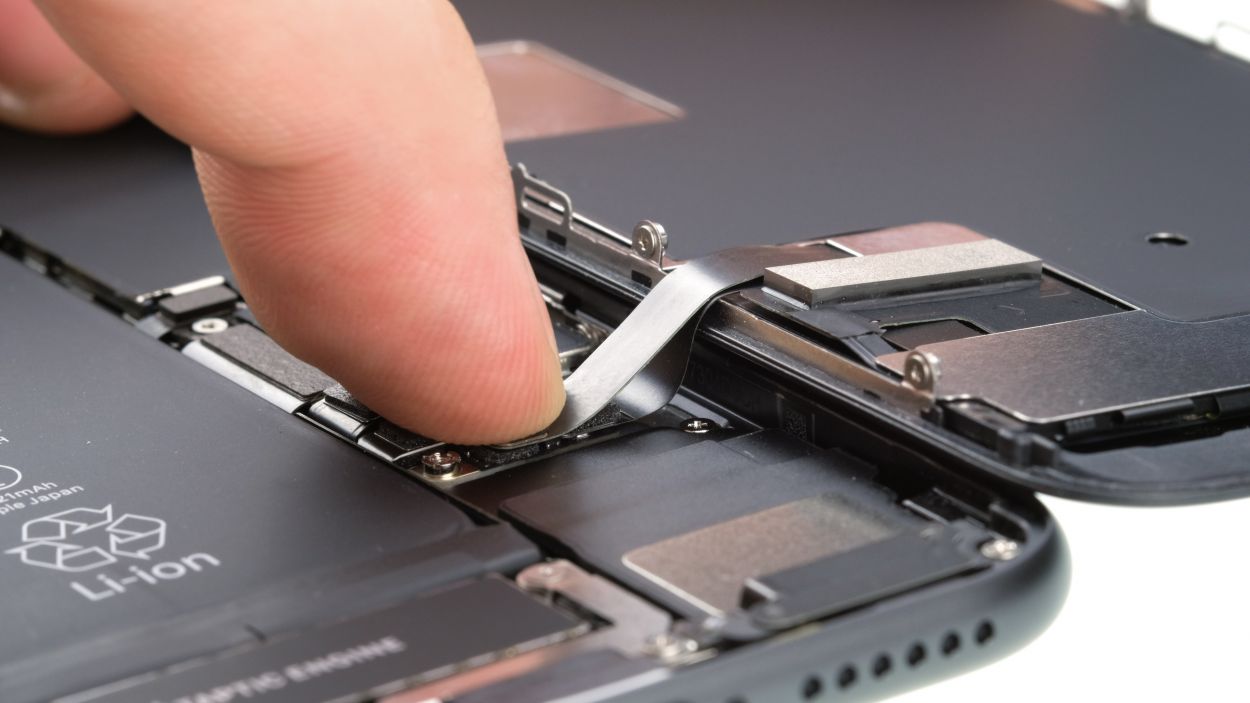
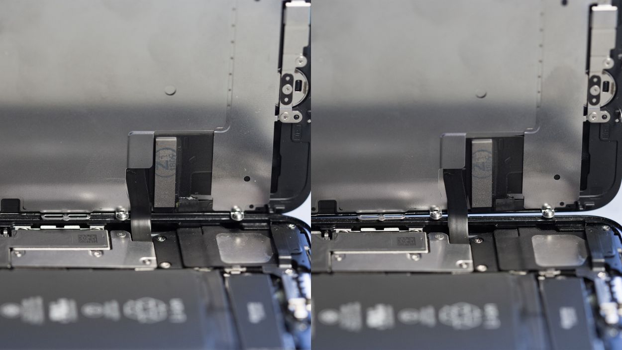
Wrong position
Right position
Hey there, superstar! Just a quick heads up: make sure that silver chip on the cable is sitting pretty just like it was before (check out the photo!). If it’s not, you might end up with some funky discolorations and spots on your screen after you finish up. If that happens, no worries—just double-check the cable’s position and line up that chip just like in our pic. You’ve got this!
Step 38
2 × 3.4 mm Pentalobe
– Time to wrap things up! Grab those two pentalobe screws that you set aside earlier and give them a nice twist back into their cozy spots on either side of the Lightning connector. You’re doing fantastic!
Tools Used