
DIY Guide to Replace MacBook Pro 15 Antenna Cables
Duration: 45 minutes
Steps: 35 Steps
Hey there, super tech! Just a heads-up, make sure to handle the components with care and keep your workspace organized. Let’s make this repair smooth and snazzy!
Follow this snazzy guide to swap out those rebellious antenna cables without having to ditch your entire display. Keep your tech vibe alive and kicking!
Step 2

– Unscrew the trio of identical Phillips screws guarding the memory door.
– Keep track of which screws came from which spot. It’s a real game-changer during reassembly!
Step 3

– Gently hoist the memory door just enough to grab onto it, then shimmy it toward yourself and whisk it away from its cozy casing.
Step 4

– Unscrew the two Phillips screws chilling by the latch in the battery compartment.
Step 5

– Unscrew these 6 bad boys:
Step 6

– Unscrew the fabulous four Phillips screws chilling on the port side of your computer.
Step 7

– Twist your computer 90 degrees and unscrew the two Phillips screws chilling at the back of the computer.
Step 8

– Twist your device 90 degrees once more and unscrew the four Phillips screws from the side. Almost there, keep it up!
Step 9

Hold your horses! Don’t just rip off the upper case like it’s a band-aid. There’s a sneaky ribbon cable connecting it to the logic board. Let’s keep it classy and gentle!
– Start by lifting up the rear of the case. Wiggle your fingers along the sides to loosen it up as you go. Once the sides feel loose, give the case a little rock and roll—up and down—to unhook the front part. This part can be a bit of a puzzle, especially over the DVD reader where you’ll find four sneaky tabs that you need to pull out vertically.
– Heads up: the two petite tongues on the left front of the upper case might get a bit bendy as you remove the case. No worries, though! When you’re putting it all back together, just give them a gentle bend back into the grooves on the lower case.
Step 10

– Unplug the trackpad and keyboard ribbon cable from the logic board, peeling off any tape that’s in the way.
– Whisk away the upper case.
Step 11

– Unplug those two snazzy antenna cables from the Airport Extreme card.
– The white antenna cable struts its stuff on the left side of the Airport Extreme card.
Step 12

– Wiggle those Airport antenna cables out of their cozy nook in the left speaker. It’s like they’re sneaking out of bed—shh, don’t wake the neighbors!
Step 13

– Unplug the iSight, inverter, and left fan cables from the logic board with a gentle tug in the direction they’re coming from.
Step 14

– Unplug the display data cable from the logic board with style.
Step 15

– Unscrew the shiny silver T6 Torx screw that’s holding the ground loop tight to the display data cable and the case. You’re doing great!
Step 16

– Hold onto the screen with one hand and cheerfully remove the following 3 screws:
Step 17

– Grab each side of the display assembly and gently lift it away from the computer like you’re lifting a slice of pizza out of the box.
Step 18


– Unscrew the two 5 mm Phillips screws chilling at the lower left and right corners of the display. Just two screws, easy peasy!
Step 19


– Slide the flat end of a spudger into the gap between the plastic strip on the rear bezel and the front bezel. Make sure it’s perpendicular to the display for a perfect fit!
– While keeping the spudger in place, give it a twist away from the display to start the magic of separating the front and rear bezels.
– Glide along the left side of the display with your spudger tool, gently but firmly, until the rear bezel pops away evenly from the front. It’s like opening a treasure chest, but what you’re finding is the chance to fix what’s inside!
Tools Used

Step 20


– Pop the flat end of your spudger into the tiny gap between the plastic strip on the rear bezel and the front bezel—like you’re diving into a tech sandwich!
– With your trusty spudger still in place, give it a twist away from the display. It’s like opening a cool, techy treasure chest!
– Slide along the right edge of the display, prying gently as you go, until the rear bezel and front bezel are chilling apart like old friends.
Tools Used
Step 21


– Wedge the flat end of your spudger between the front bezel and the plastic strip clinging to the rear bezel near the bottom corners of the display.
– Twist your spudger toward the back bezel to pry it apart from the front bezel.
– If needed, gently widen the gap between the lower edge of the rear bezel and the clutch cover until they’re totally separated.
Tools Used

Step 23

Heads up! The display inverter is super slim and super fragile. Handle it like you would a rare comic book or your favorite vinyl record. Let’s keep it in one piece!
– Gently hoist the inverter board from its cozy spot in the clutch cover.
Step 24

– Unplug the LCD backlight from the inverter by gently tugging its connector away from the inverter board. Let’s keep things light and easy!
Step 25

Hey, take it easy with the inverter cable ground loop—it’s super thin and fragile, like a spaghetti noodle on a diet!
– Unplug the inverter cable by gently tugging its connector from the inverter’s socket. Let it go free!
Step 26


– Whisk away those sunny pieces of yellow kapton tape from the cozy bottom left nook of the display.
– Gently persuade the trio of green antenna ground straps to part ways with the copper tape along the lower rim of the LCD.
– Unstick that sneaky piece of tape that’s been holding the camera cable hostage to the LCD.
Step 27


– Peel off those sticky tapes covering the display data cable and camera cable connectors like unwrapping a present.
– Gently lift the camera cable off the squishy foam tape along the top edge of the LCD, like peeling a banana.
Step 28


– Carefully slide the camera cable out of its cozy home on the camera board.
– Eject the display data cable connector from its hangout spot on the LCD like a boss.
– Yank both cables parallel to the face of the logic board with all the smoothness of a jazz solo.
Step 29


– Got a Core Duo device? Check out picture 1 and whisk away three Phillips screws that are keeping the clutch assembly cozy with the lower edge of the front display bezel near the display data cable.
– Rocking a Core 2 Duo Model A1211? Peep picture 2 and gently remove two Phillips screws that connect the clutch assembly to the lower edge of the front display bezel, right by the display data cable.
Step 30

– Unscrew that tiny Phillips screw hiding behind the display data cable. Sneaky little guy!
– Slide out the small rectangular steel bracket from its cozy spot next to the right clutch hinge.

Step 32


Feel free to repeat this nifty maneuver for the right side of the clutch assembly if needed. Keep the vibes high and the fixes coming!
Step 33

– Unscrew the five cheeky little Phillips screws that are holding the plastic antenna cover in place on the inside of the clutch cover. You’re doing great!
Step 34

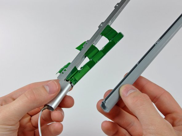
– Gently wiggle the antenna cover off the clutch cover without yanking those precious antenna cables. Easy does it!
Step 35

– Gently free those antenna cables from the clutch cover’s grasp, keeping an eye on those sneaky connectors trying to play tag with the cover. Keep it smooth and snappy!


