DIY Guide to Replace OnePlus 6 Screen: Step-by-Step Tutorial
Duration: 90 min.
Steps: 35 Steps
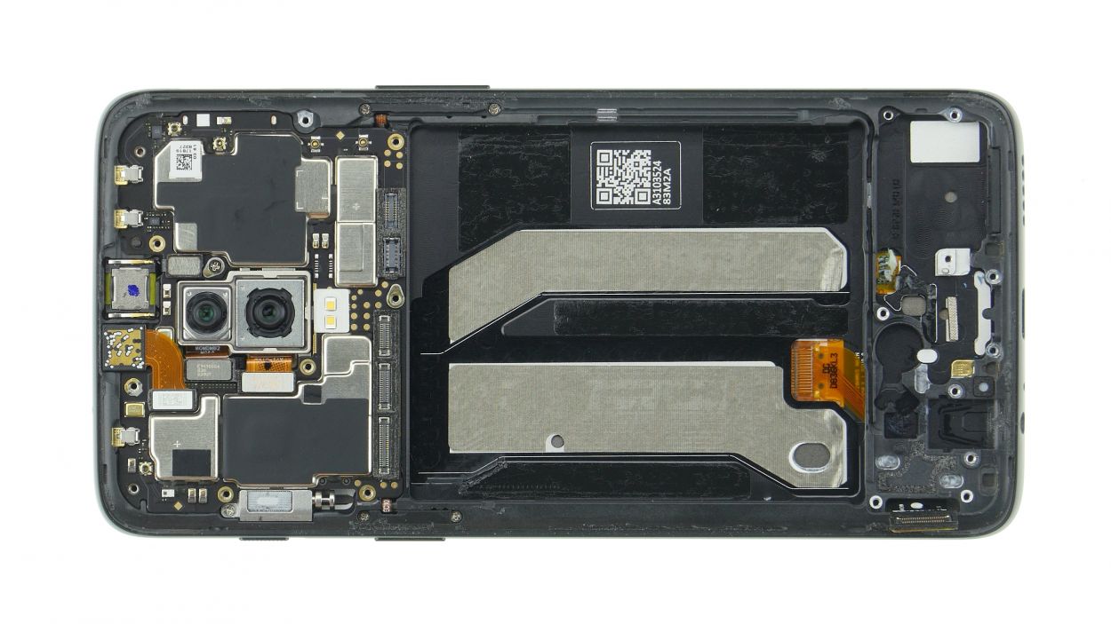
Is your display feeling a bit under the weather? No worries, you can tackle this repair yourself! Each step comes with clear photos to help you swap out that screen like a pro. We’re replacing the whole display unit here, not just the shattered glass. Depending on your spare part, you might need to salvage a few small bits from the old display, so give it a good look before diving in. If you spot any issues, reach out to your vendor before you get started. Just a heads up, this repair can be a bit tricky since you’ll need to open up the OnePlus 6 through the glass back cover. Don’t forget to back up your data, set up a tidy workspace, and take your time. If you have any questions, feel free to use the live chat on our website or drop a comment. Happy repairing!
Step 1
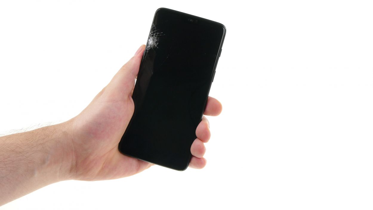
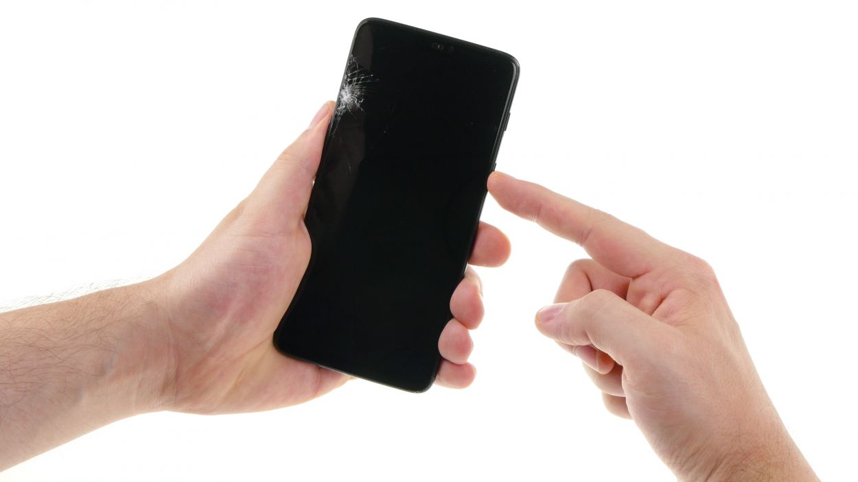
If your OnePlus 6 touchscreen is playing hard to get, no worries! Just press and hold the standby button for about 10-15 seconds to give it a little timeout. If you need help, you can always schedule a repair.
– Killer! Let’s get started Already got your fix in mind? Great! Hit the standby button and hold it tight. Wait for the ‘Switch off’ option to show up – yeah, it’s a long time! Just chill.
– Tap again, and you’re ready to roll. Easy peasy, right?
Step 2
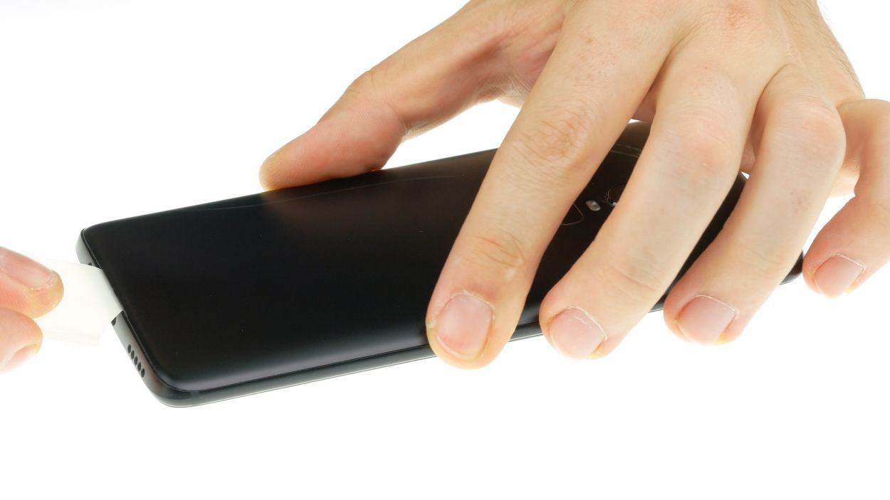
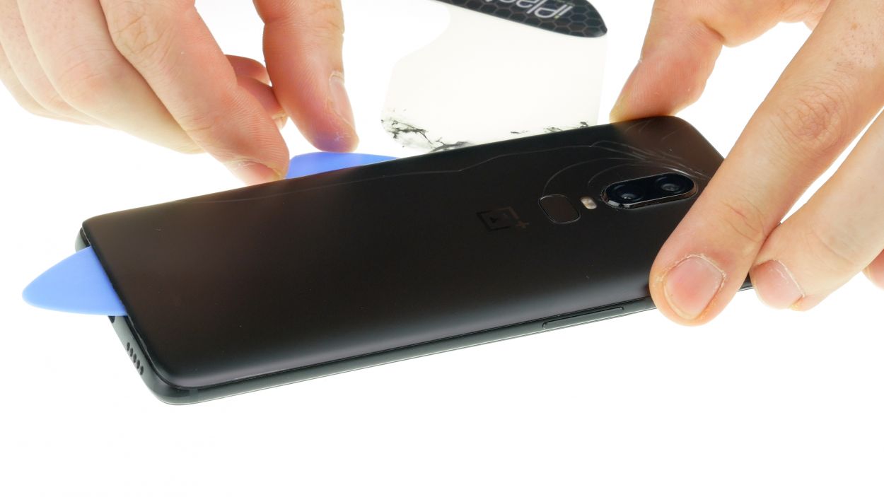
– You’ve got this! Time to heat up that tough spot with a hair dryer or heat gun (be careful, we don’t want any mishaps!). Get that adhesive nice ‘n’ toasty for the next step.
– Now it’s time to get down to business! Slide a thin, flat tool – think plastic spudger or a similar tool – between the back cover and the frame. Be gentle, don’t wanna scratch anything!
Hey there! Just a friendly reminder to handle that back cover with care—it’s a bit fragile and can crack easily. If it’s giving you a hard time, don’t hesitate to warm it up a few times and give it another go. Remember, taking your time is key; it might take around half an hour, but being patient and gentle will help you avoid any mishaps. You’ve got this!
The iPlastix is crafted from plastic, ensuring it won’t leave any scratches on your device. However, it’s a bit on the soft side and can be a little tricky to get in there. If you need help, you can always schedule a repair!
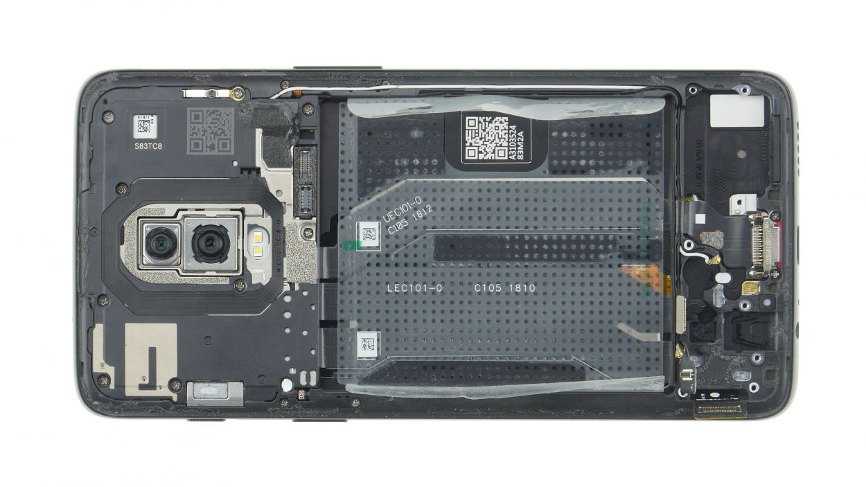
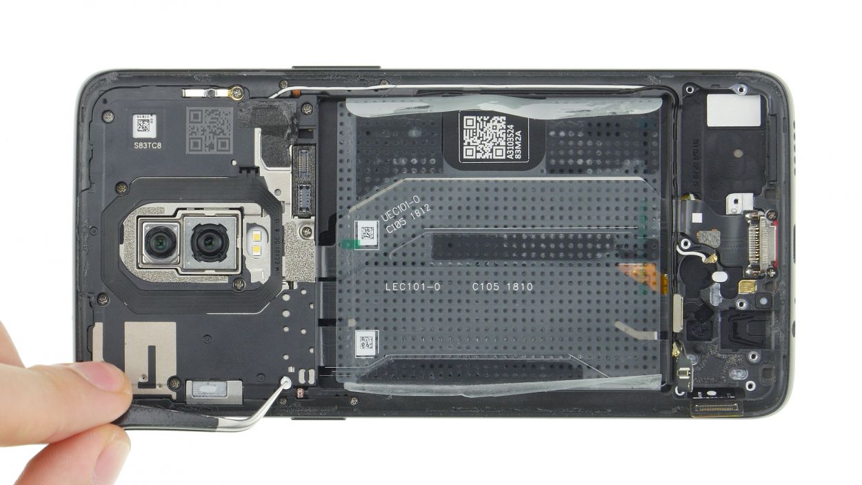
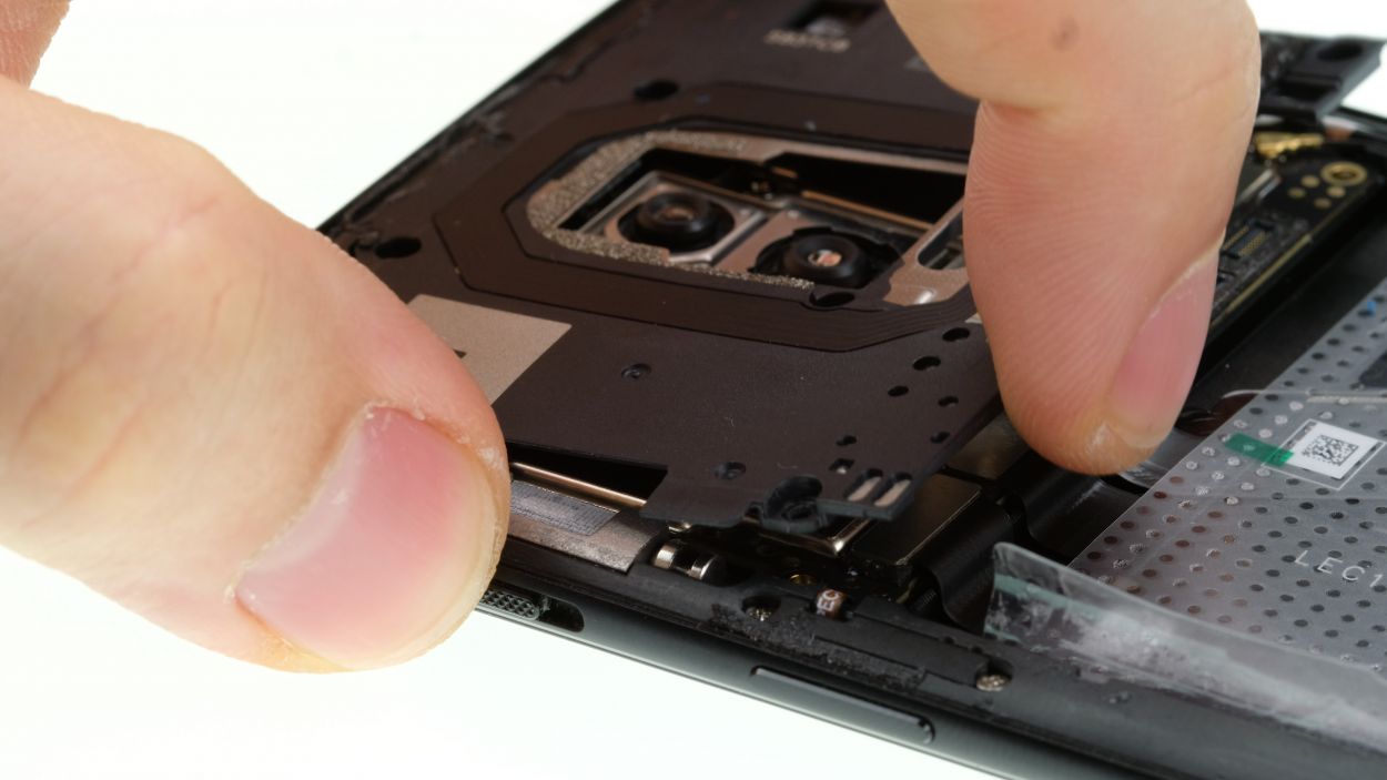
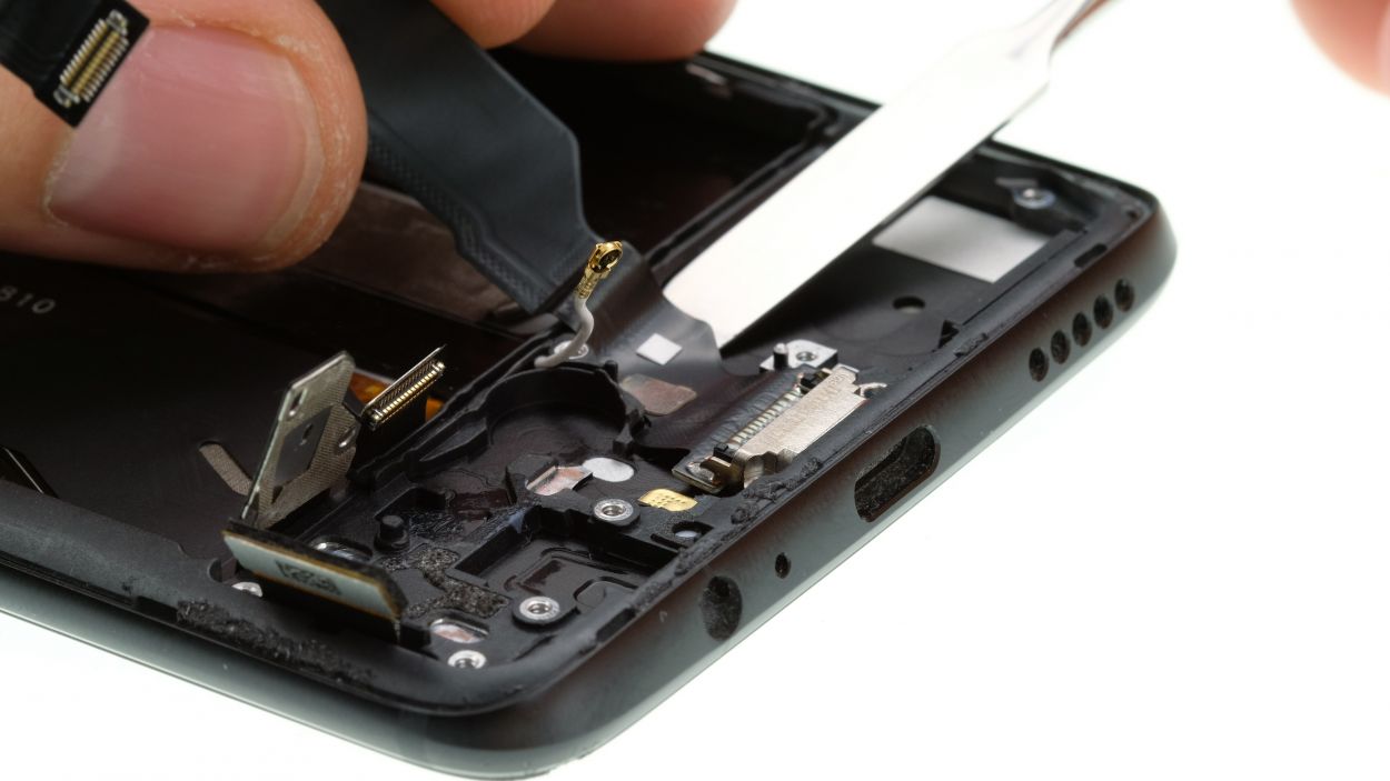
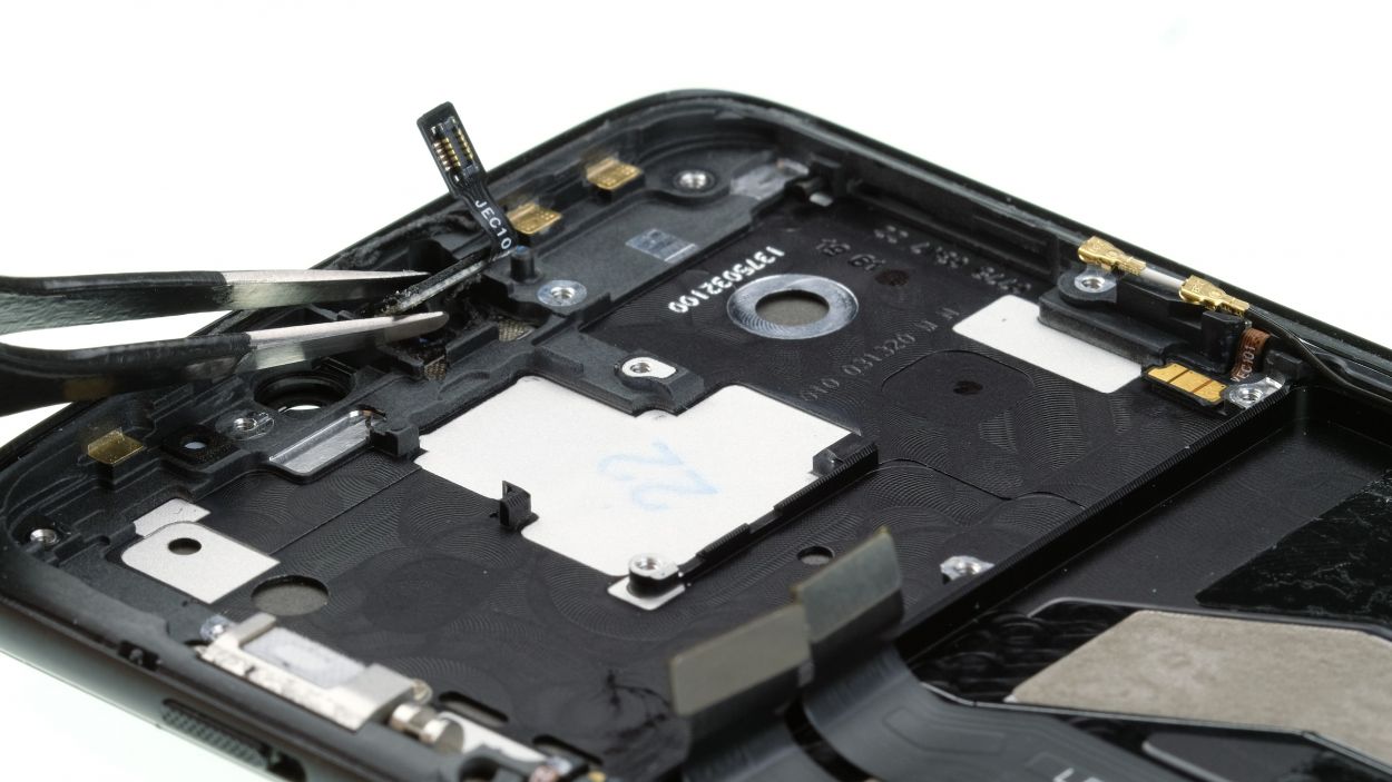
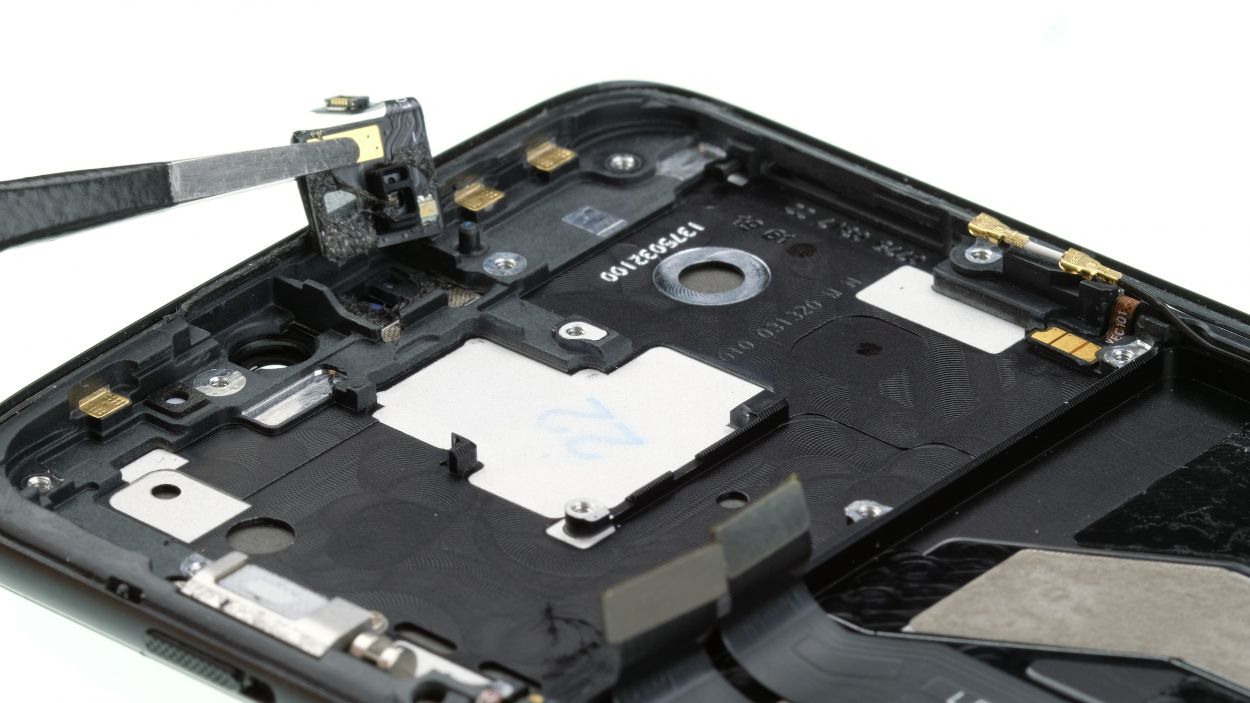
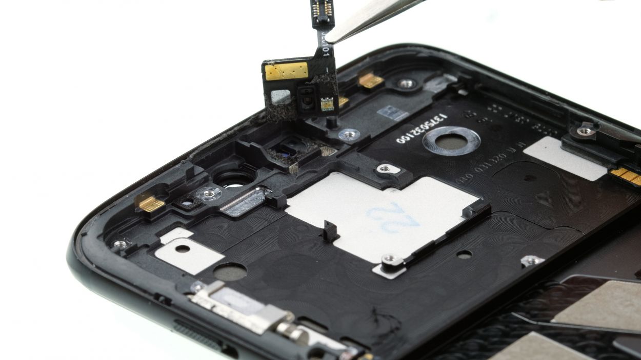
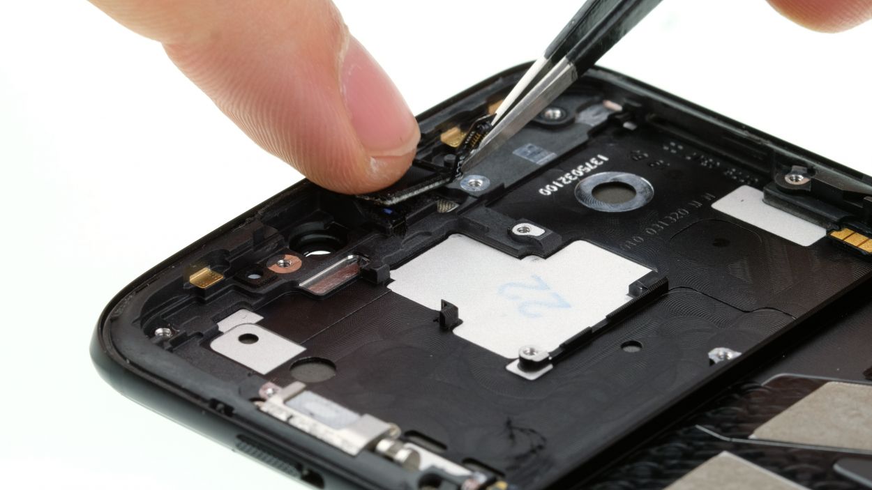
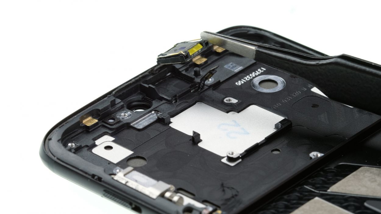
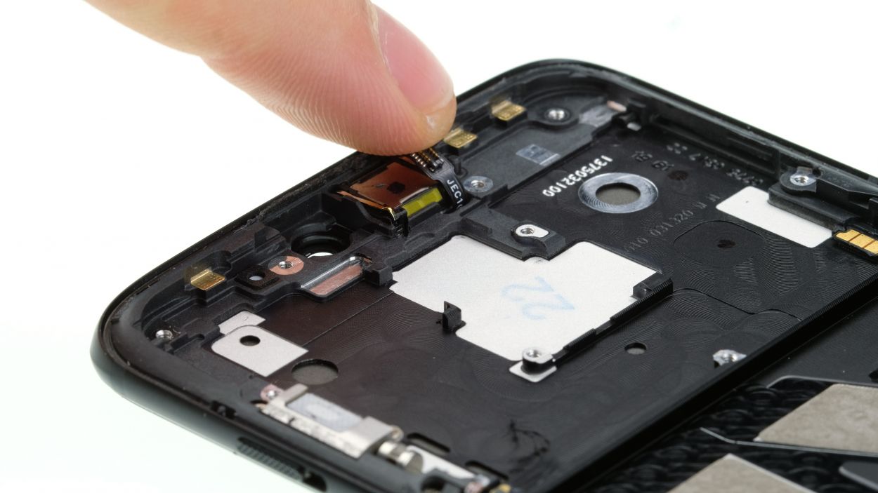
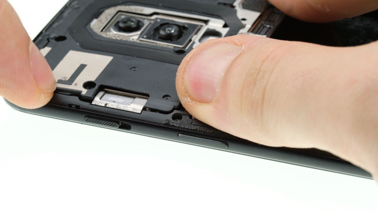
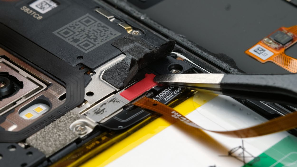
Step 3
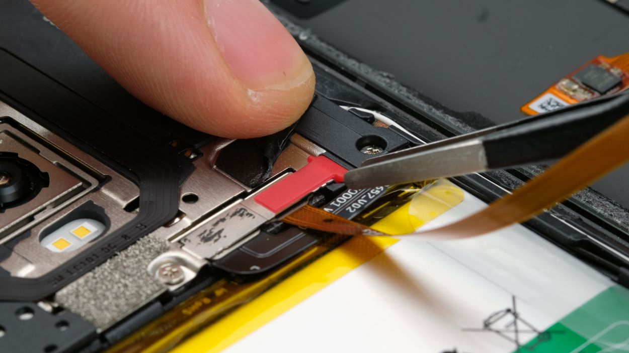
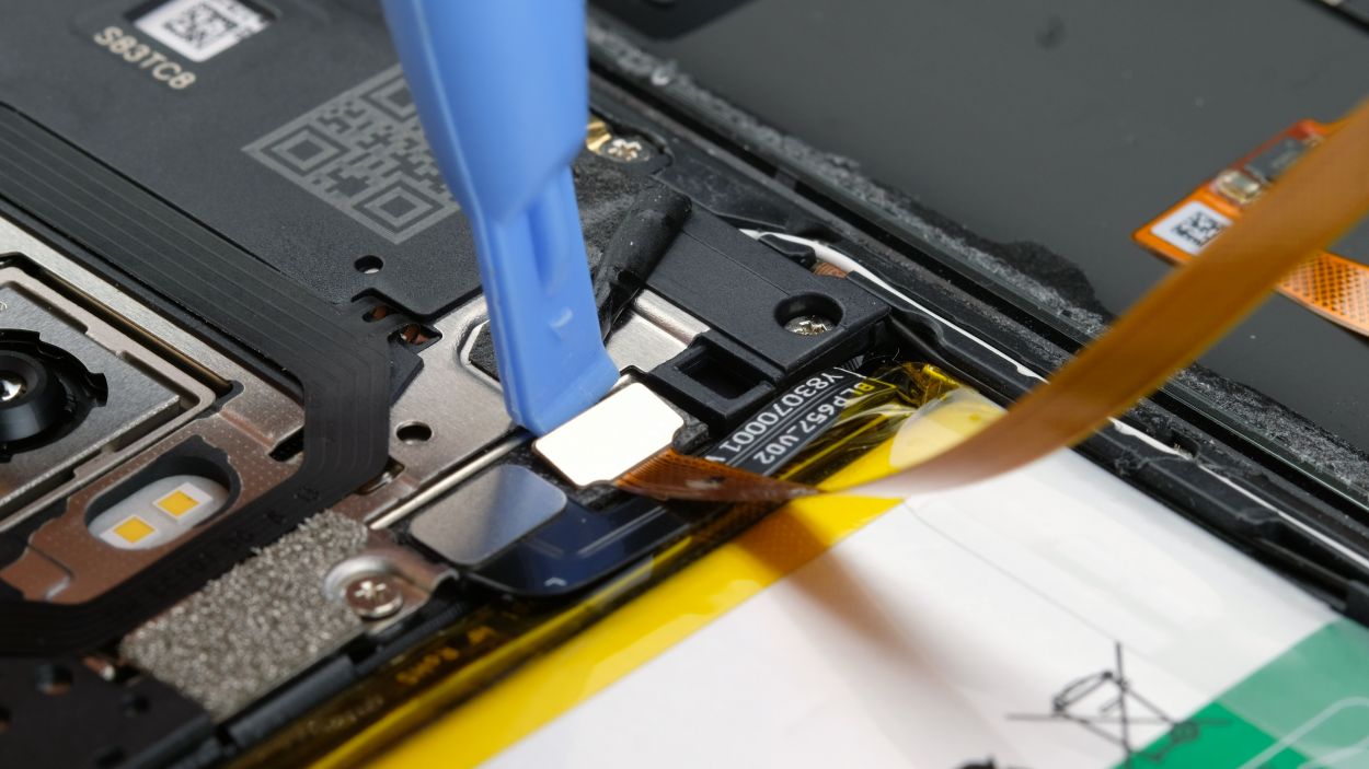
Fingerprint Connector
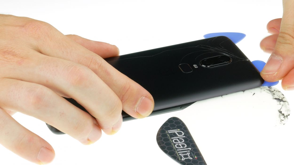
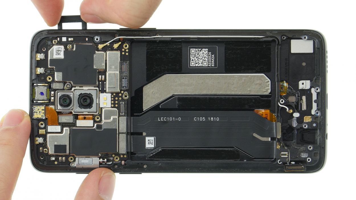
– Alright, it’s time to get your repair on! Carefully lift up that loosened back cover and give it a big ol’ fold.
– Time to get peeling! Loosen that adhesive strip over the cover plate. Easy does it!
– Now, carefully pluck out the back cover over the connector with your trusty tweezers or fingers.
– One more push, and then disconnect that connector with a spudger or your fingernail. Your back cover is about to be fully removed!
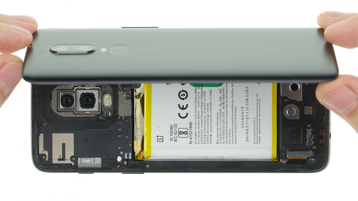
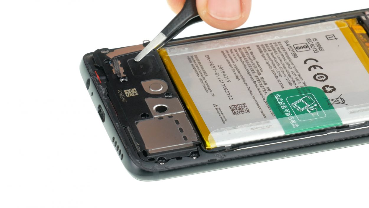
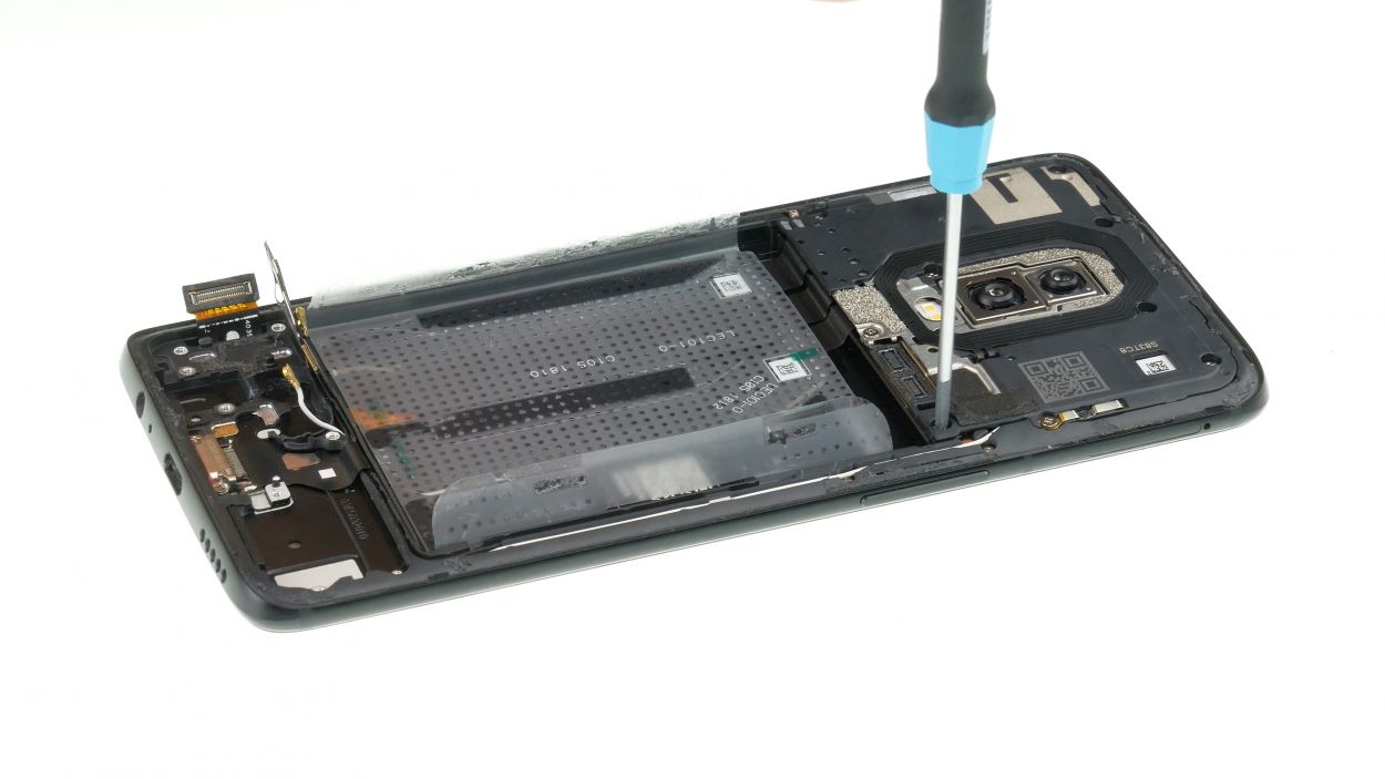
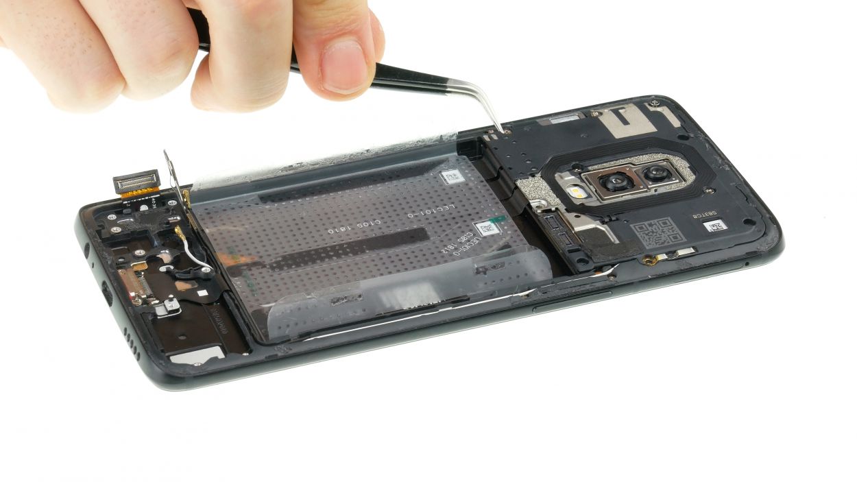
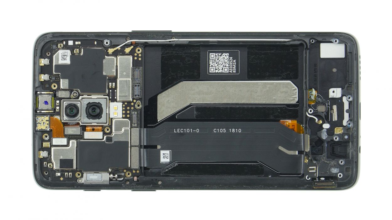
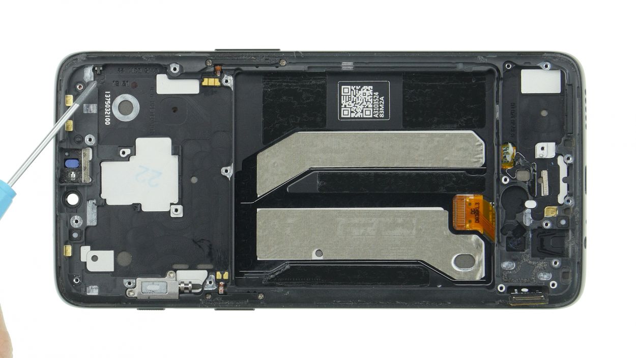
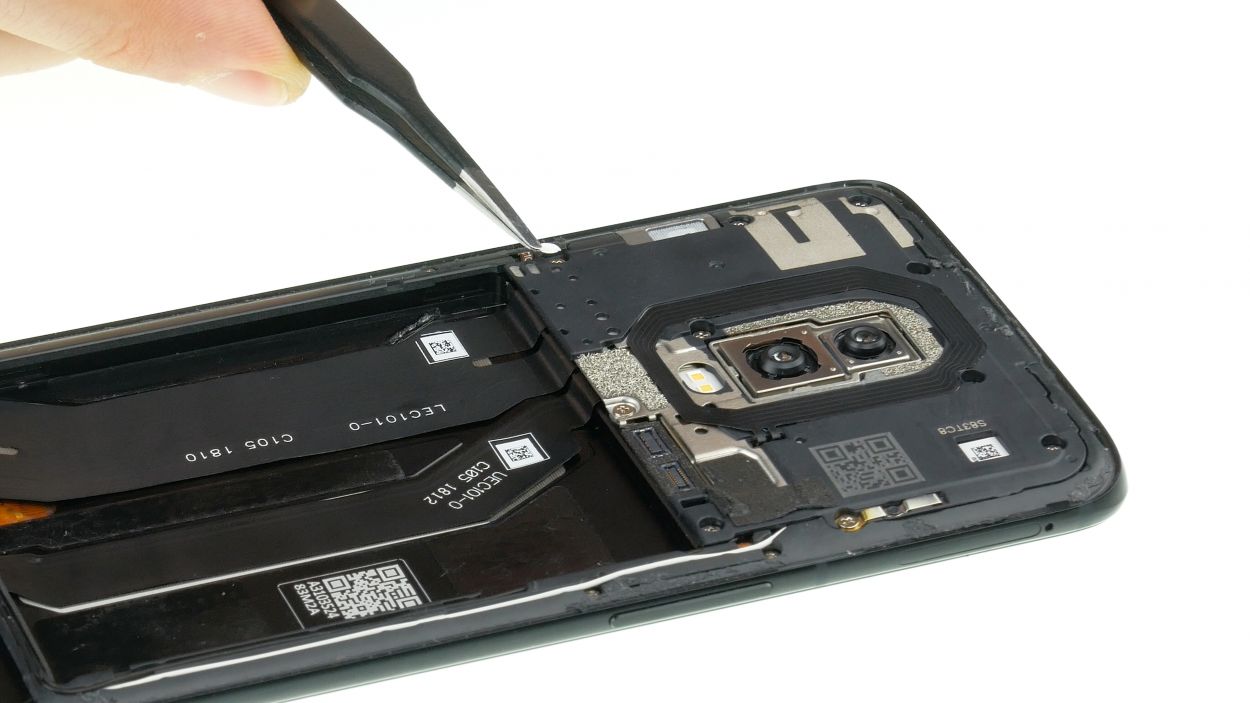
Step 5
8 × 3,0 mm Phillips
– First, let’s get those marked screws loosened and removed. You’ve got this!
– Next up, gently use your tweezers to lift off the cover. Just a heads up, the speaker is snugly tucked in there with the cover.
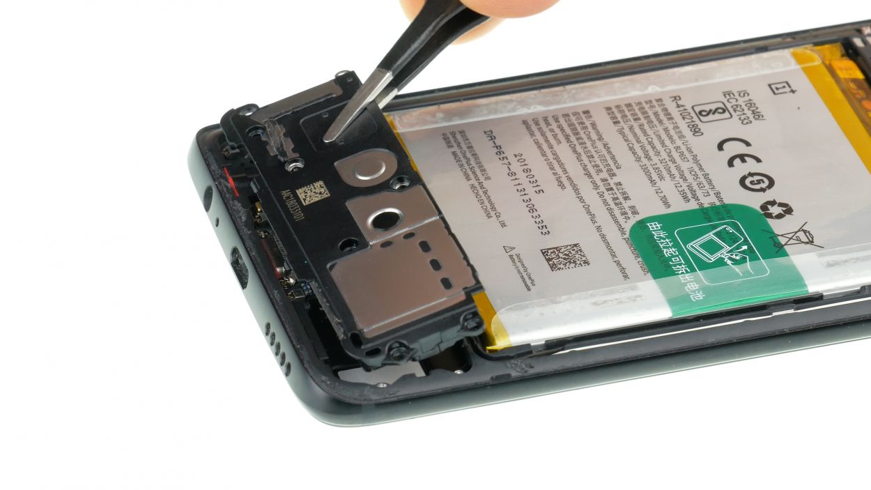
Step 6
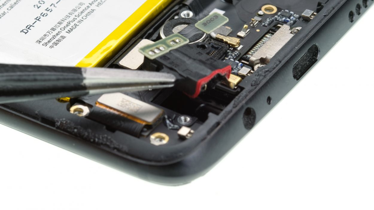
– Gently wiggle the headphone jack connector loose with your trusty spudger.
– Once it’s free, grab those tweezers and carefully lift out the headphone jack.
Step 7

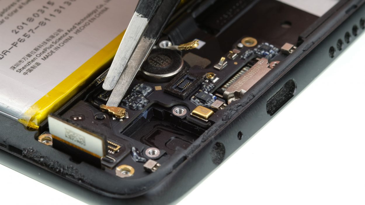
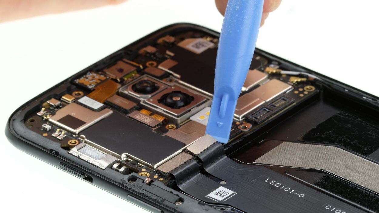
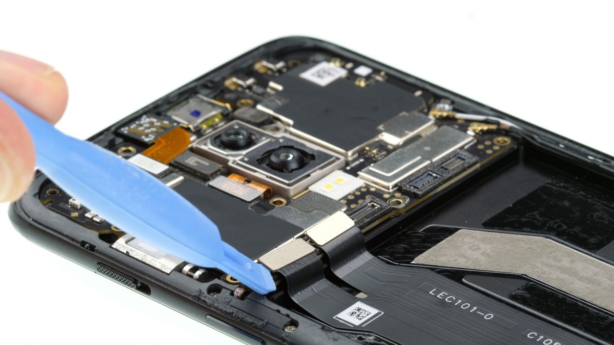
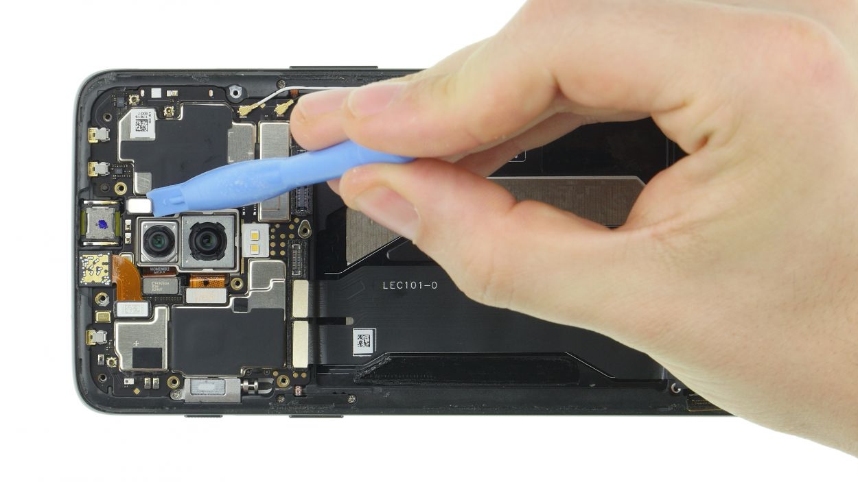
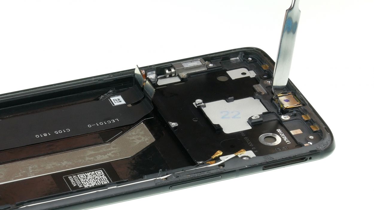
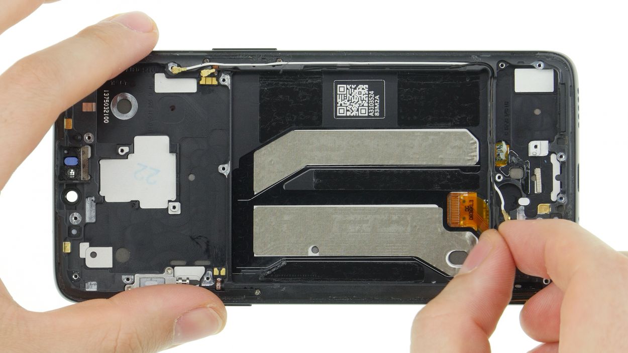
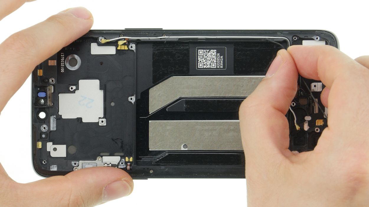
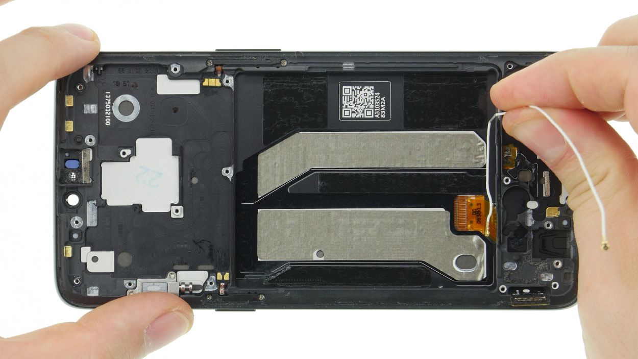
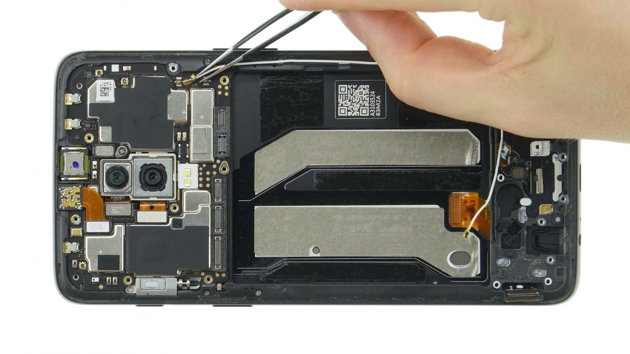
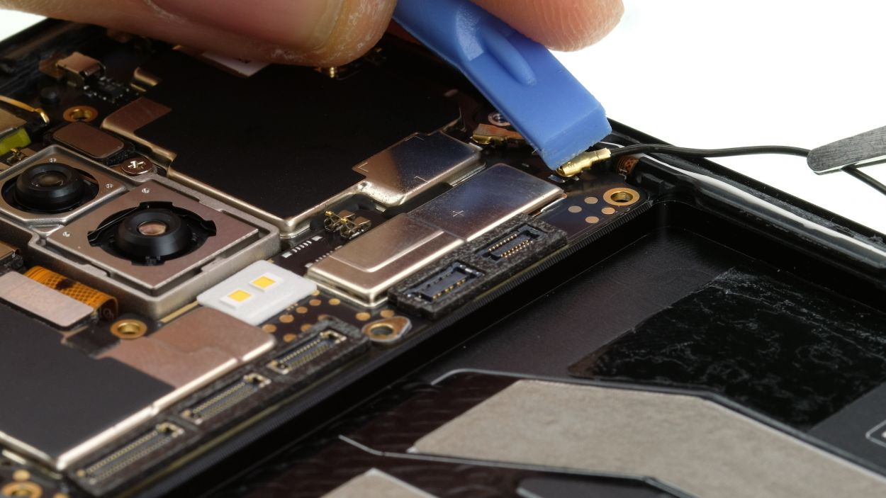
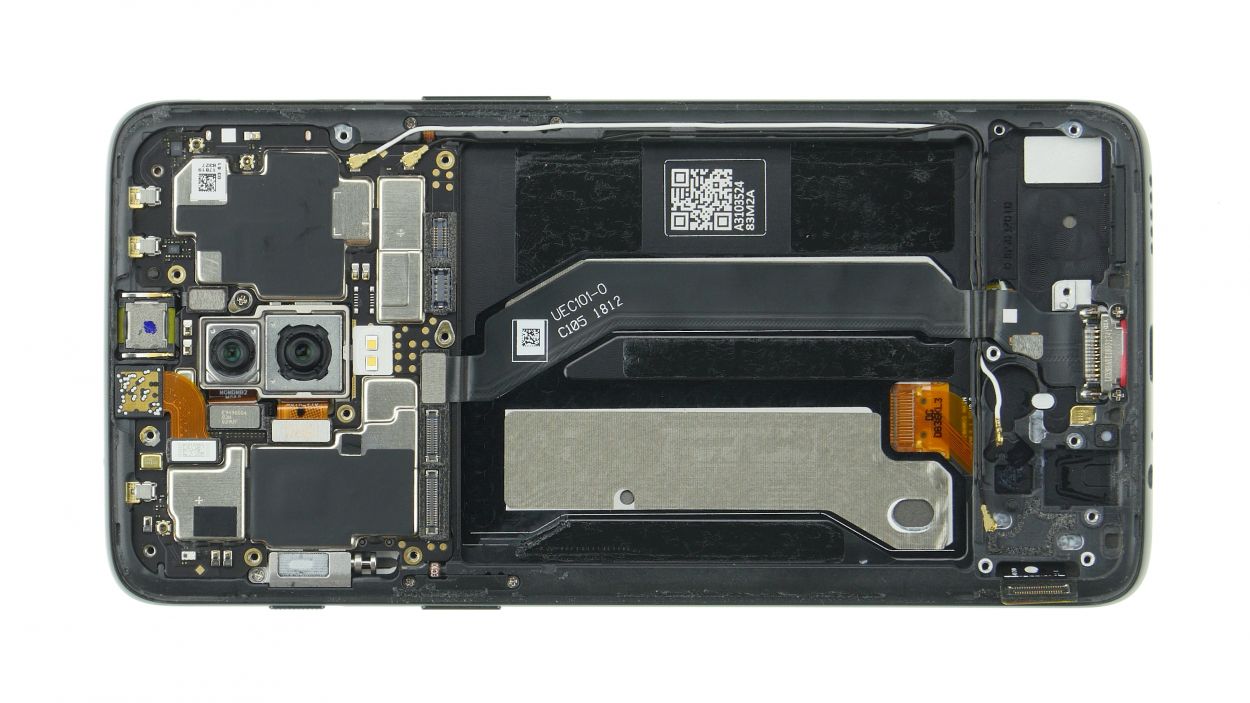
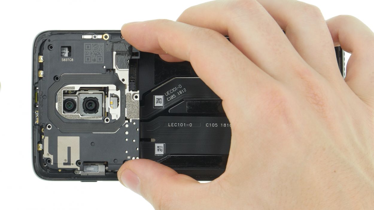
Let’s put some fun into it! 💃🕺 Though your tweezers are dancing between those antennas, remember to tiptoe around the board’s precious sockets!
– Grab your trusty spudger and gently loosen the connectors for both the display and the main board. No need to rush, just take your time!
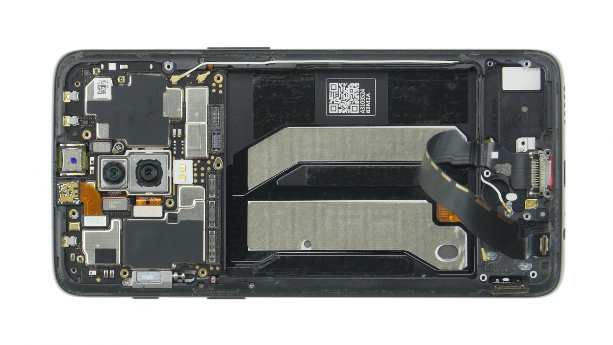
– Next up, carefully disconnect those antenna cables from the spots we’ve marked. You’ve got this!
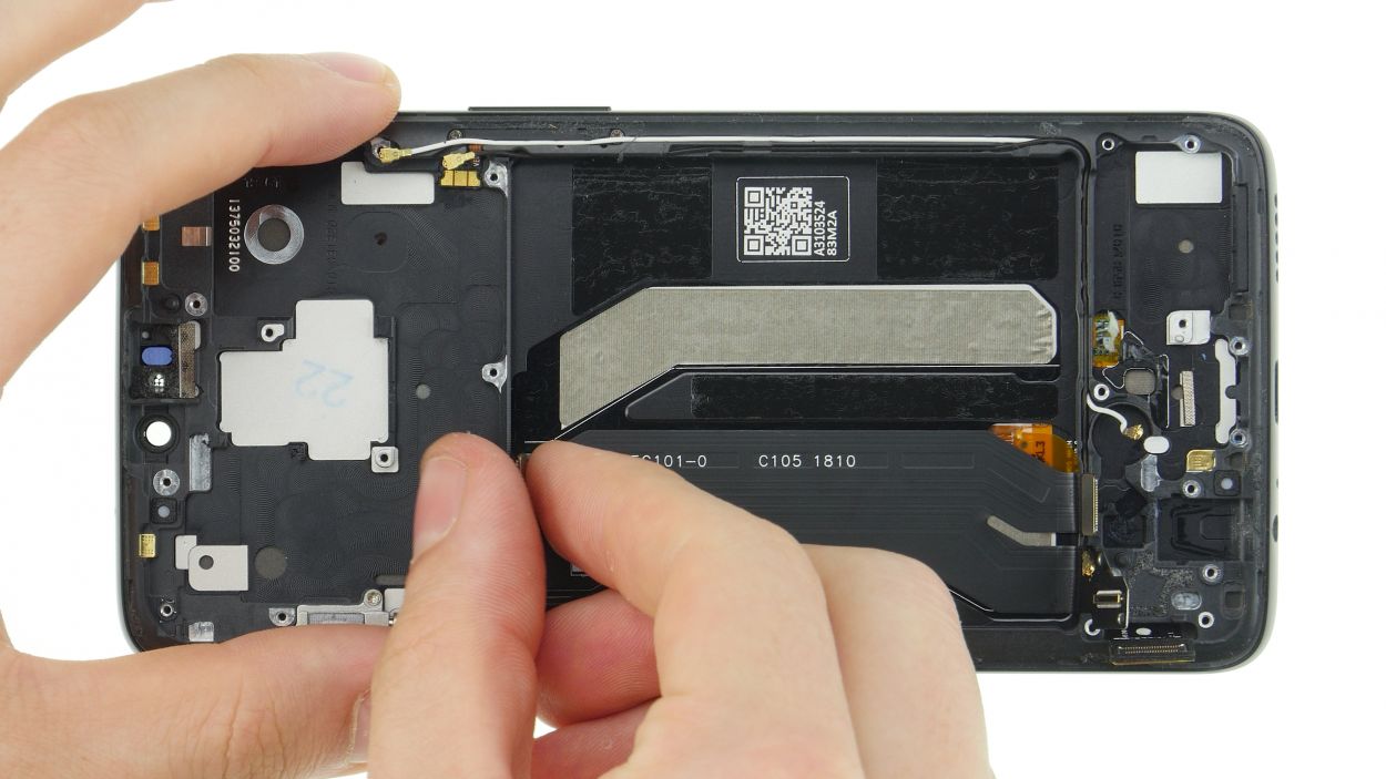
Step 8
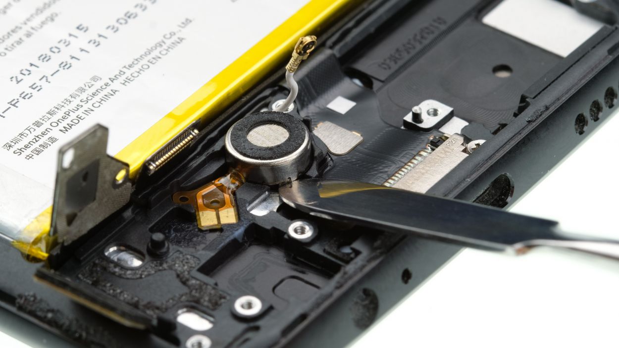
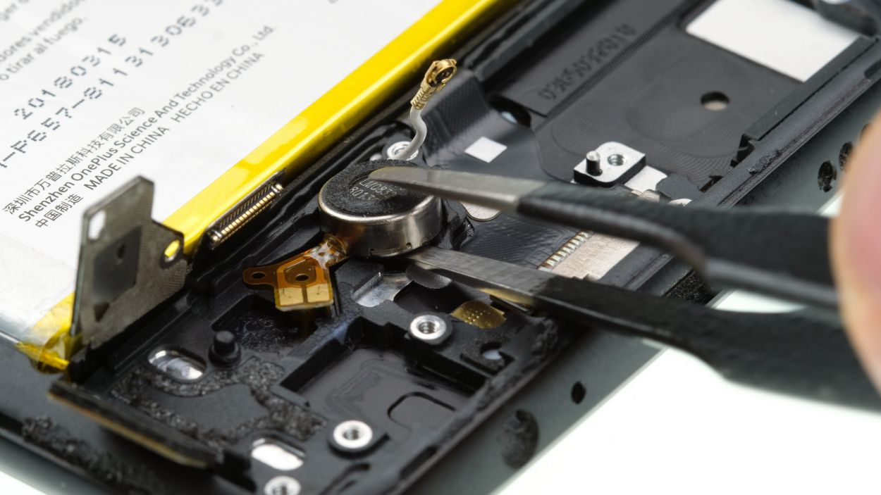
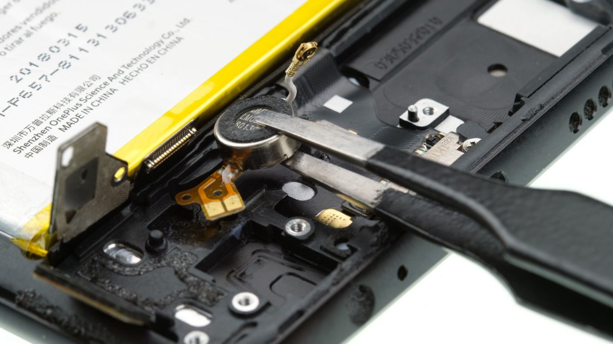
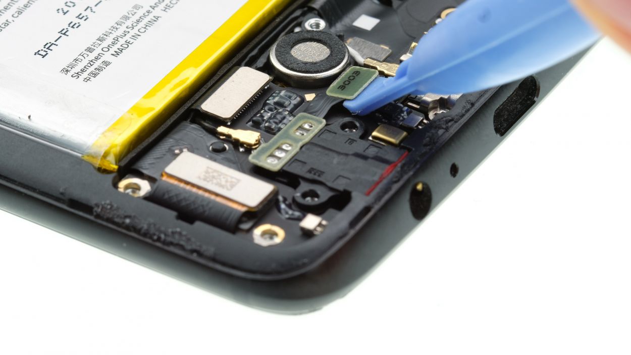
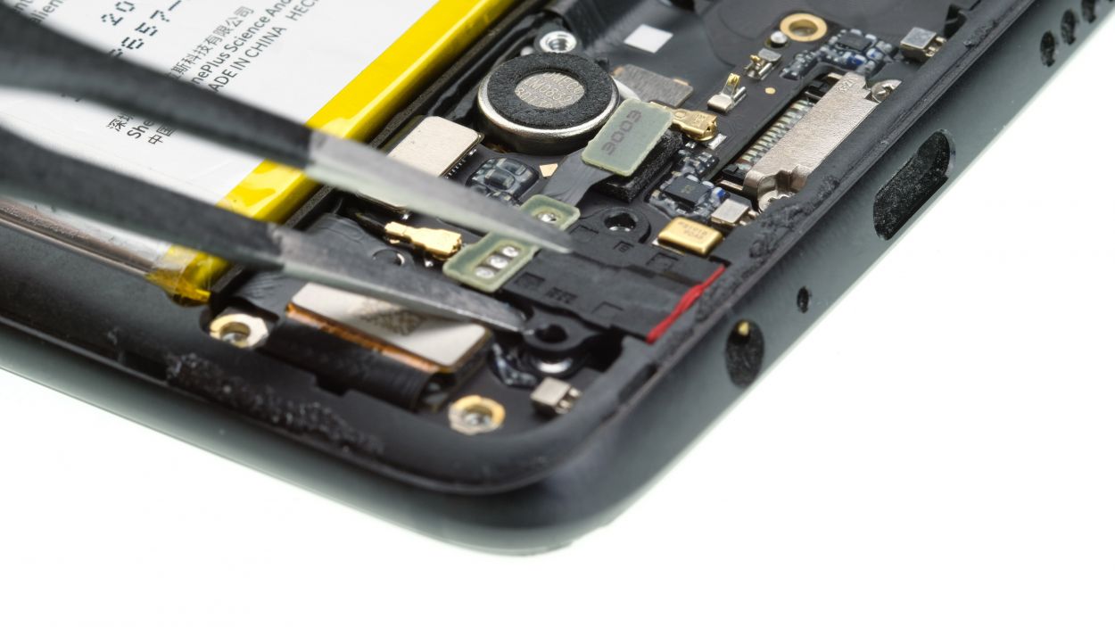
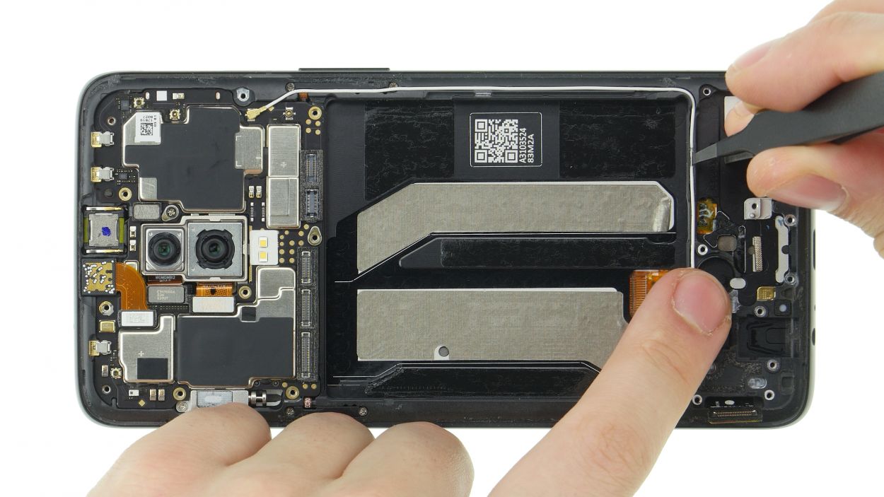
– Carefully loosen the vibration motor with a flat tool and take it out.
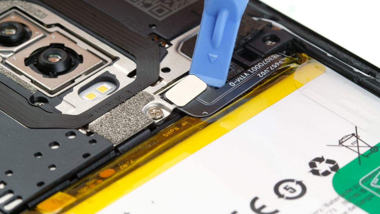
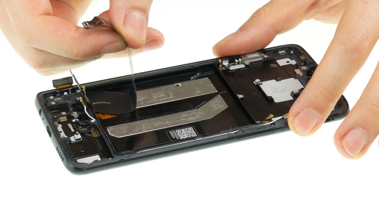
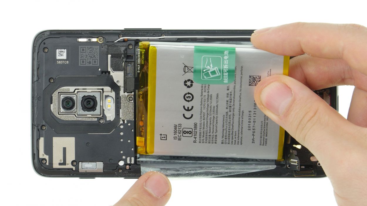
Step 9
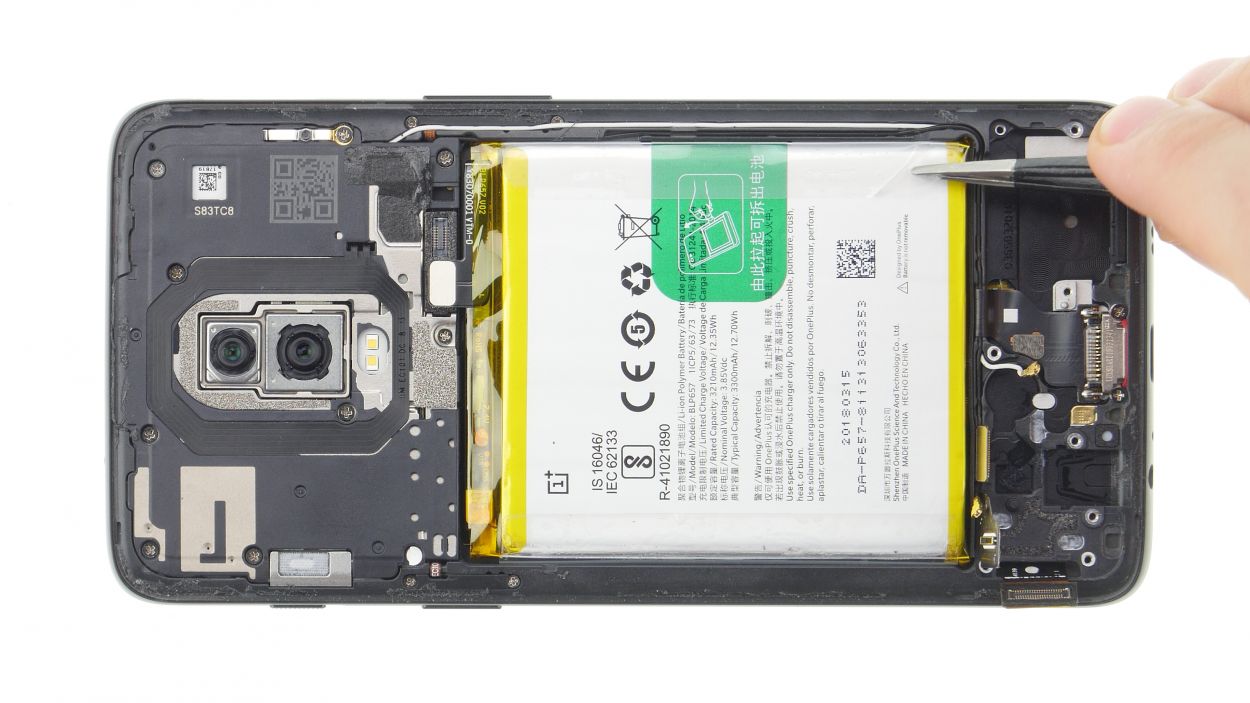
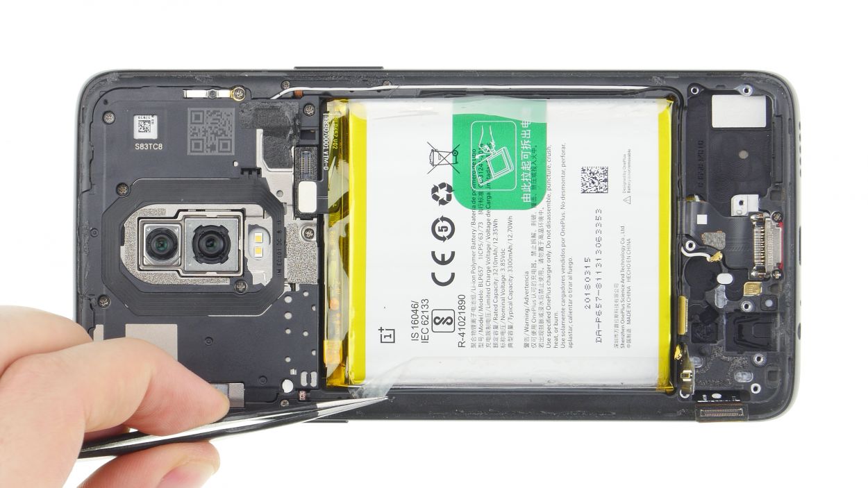
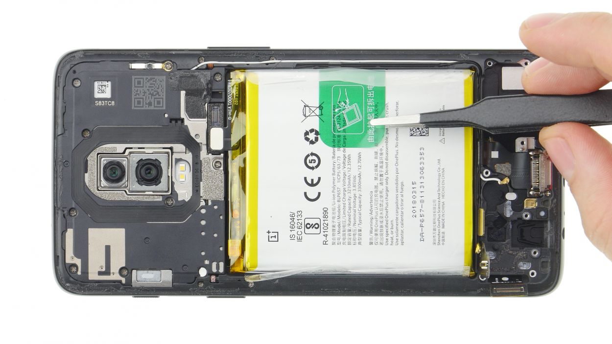
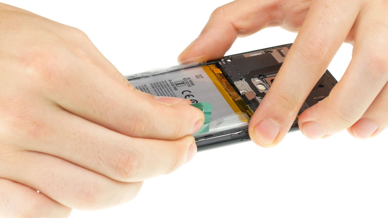
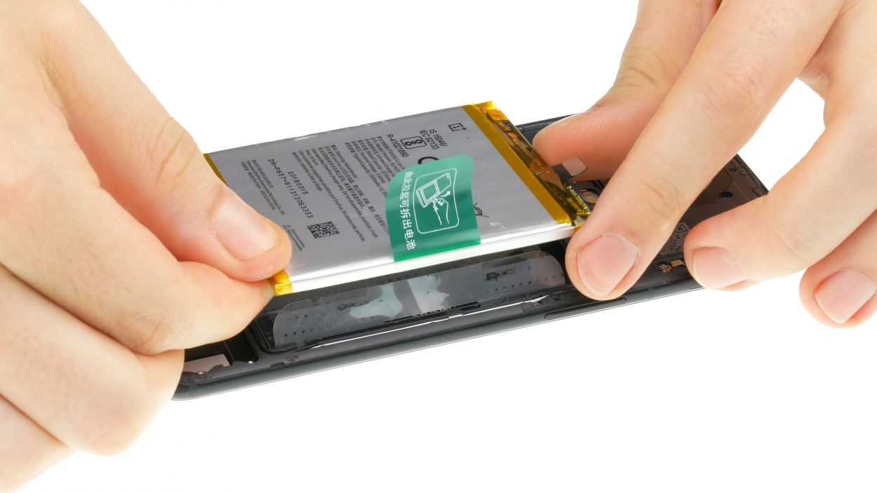
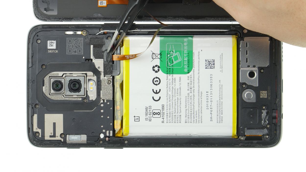
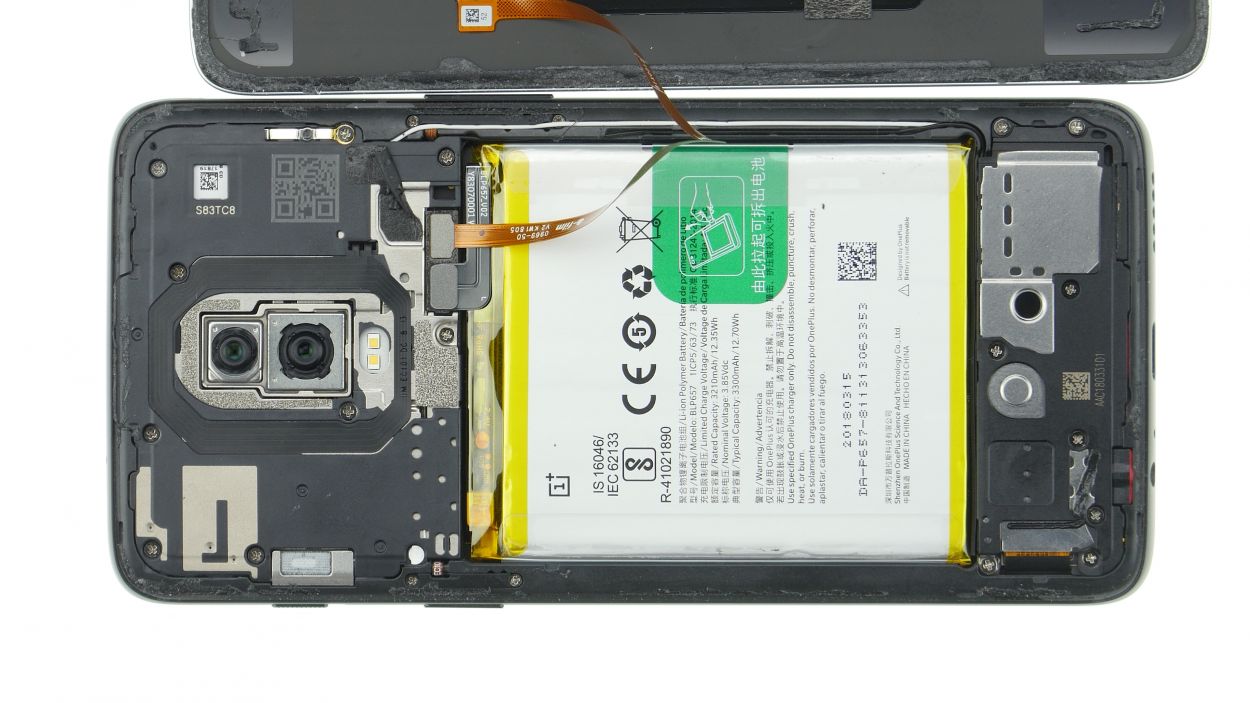
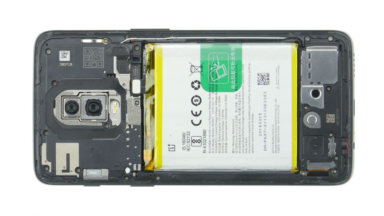
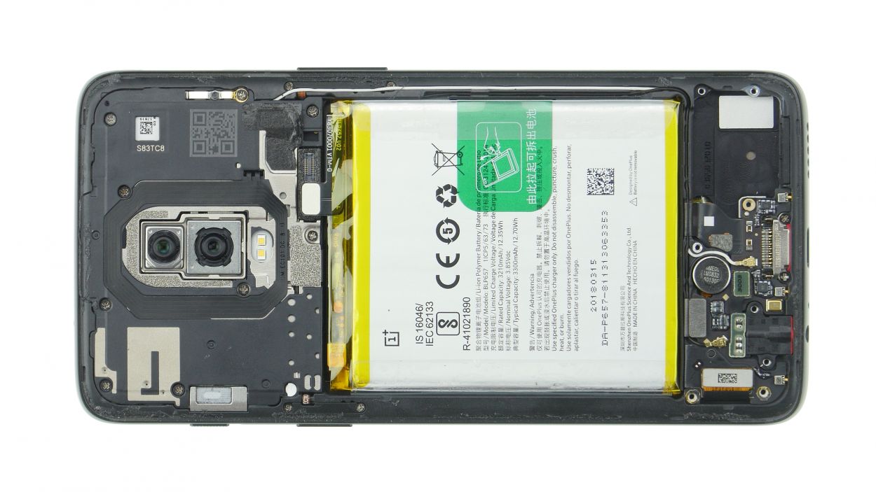
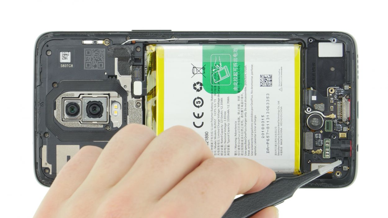
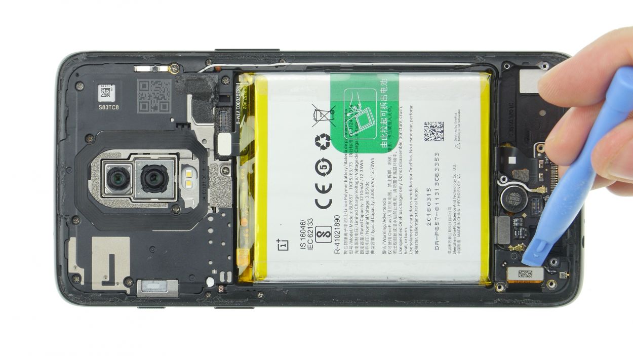
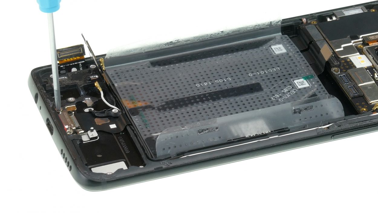
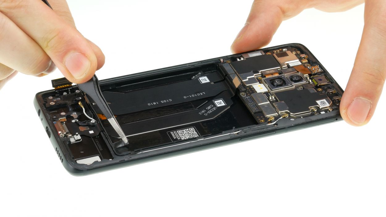
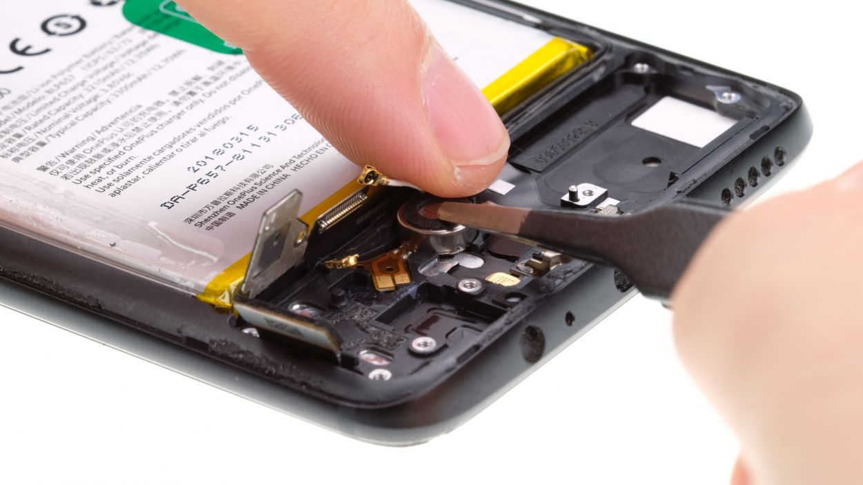
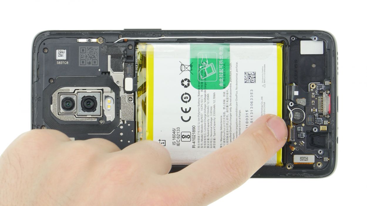
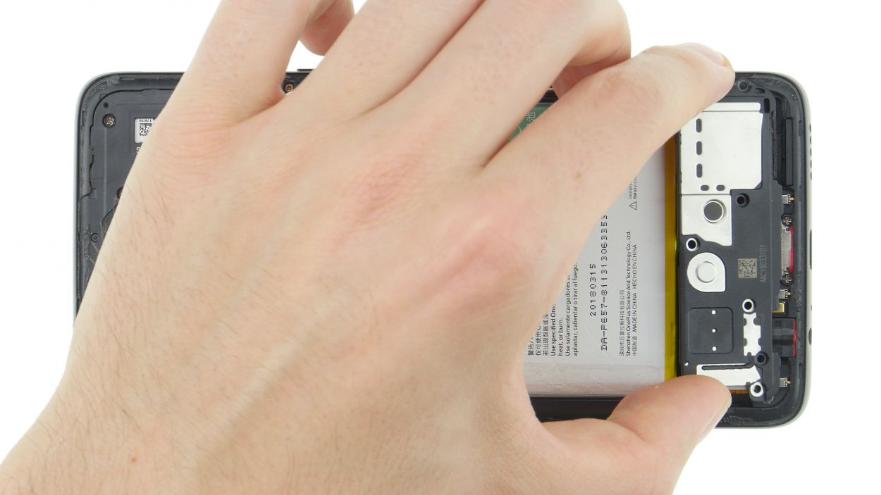
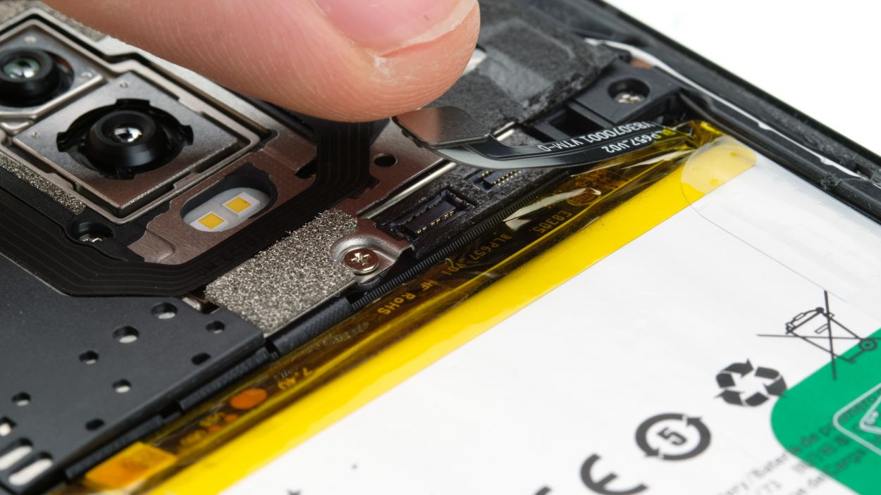
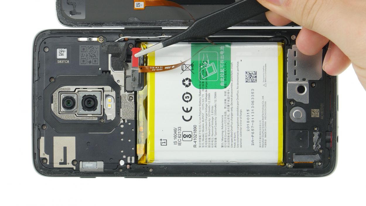
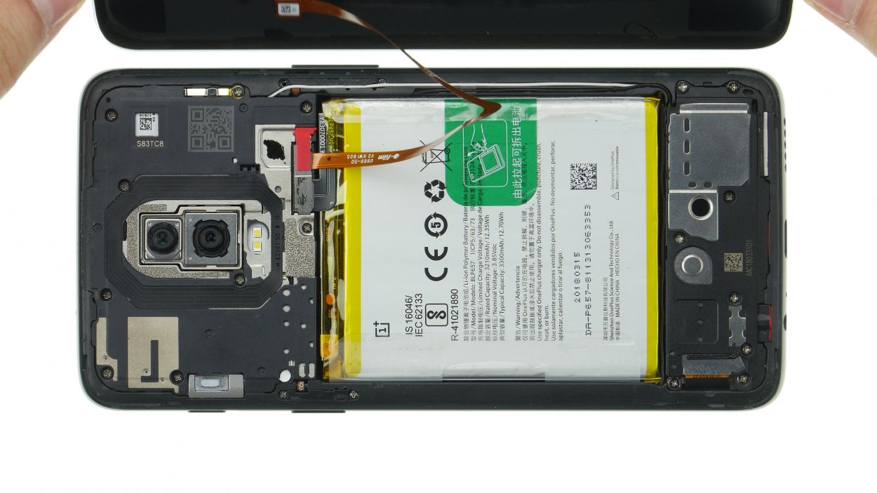
– And… it’s time to loosen things up! Carefully unstick those two transparent adhesive tabs on each side of the battery. We know it can be a bit tricky, but go easy, okay?
– Alright, here’s the next step: pull that green tab gently but firmly until the battery starts to come out. Think of it like a magic trick – just pull slowly and it’ll work its way out smoothly!
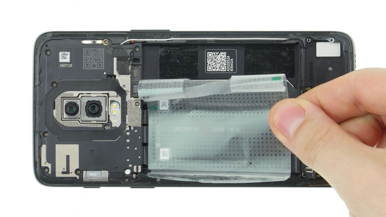
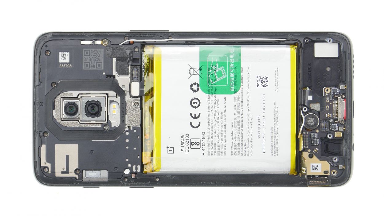
Step 10
10 × 3,0 mm Phillips
If those pesky screws decide to play hard to get, grab a trusty pair of tweezers and show them who’s boss!
– Gently take out the moisture indicator so you can pop it back in later.
– Loosen those Phillips screws with a smile!
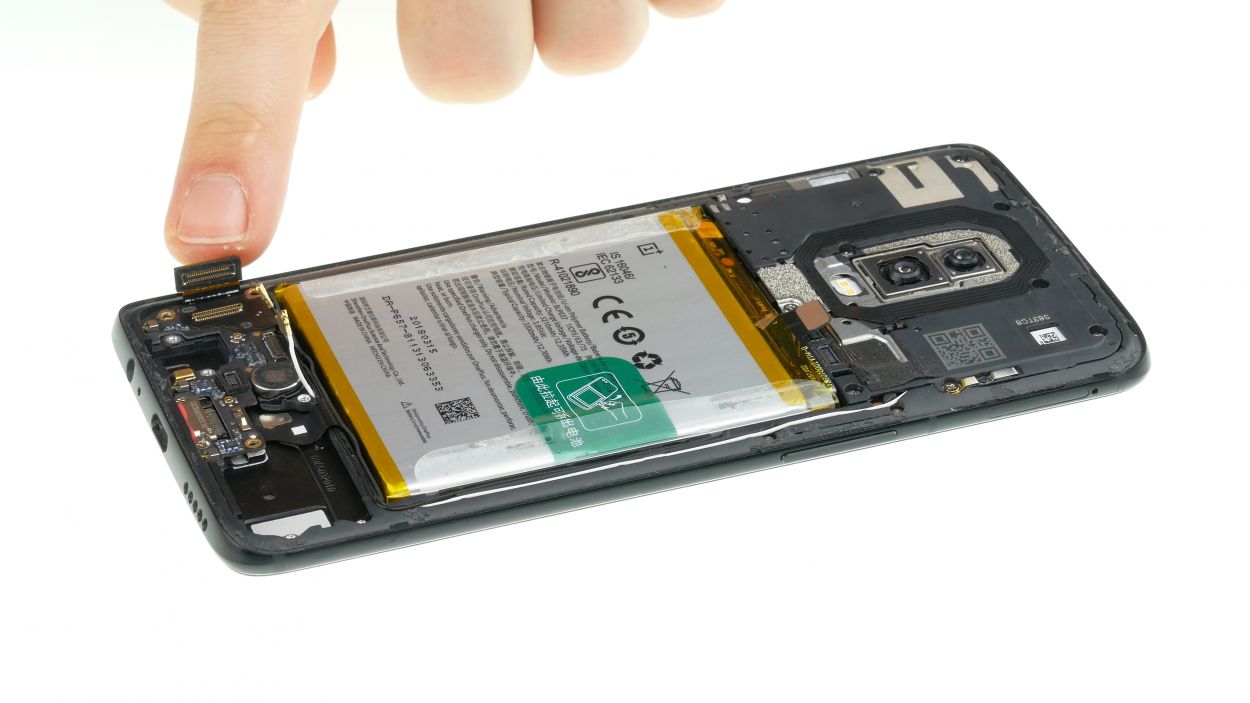
Step 11
2 × 2,4 mm Phillips
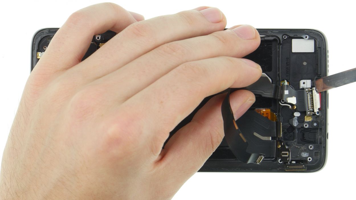
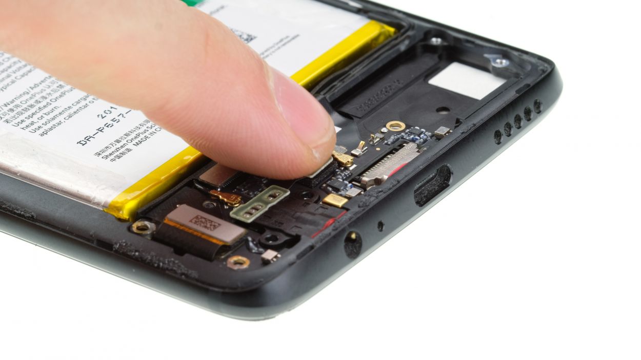
USB-Flex Connector
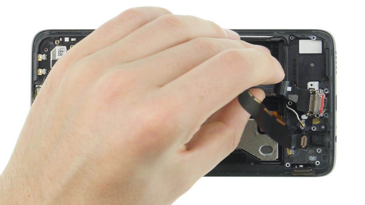
Time to get all glue-tastic! If your cable’s stuck stronger than a superglue-loving granny, just fire up your heat gun or hair dryer and gently tease that glue loose. Easy peasy!
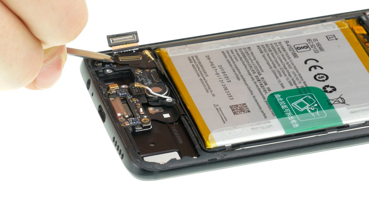
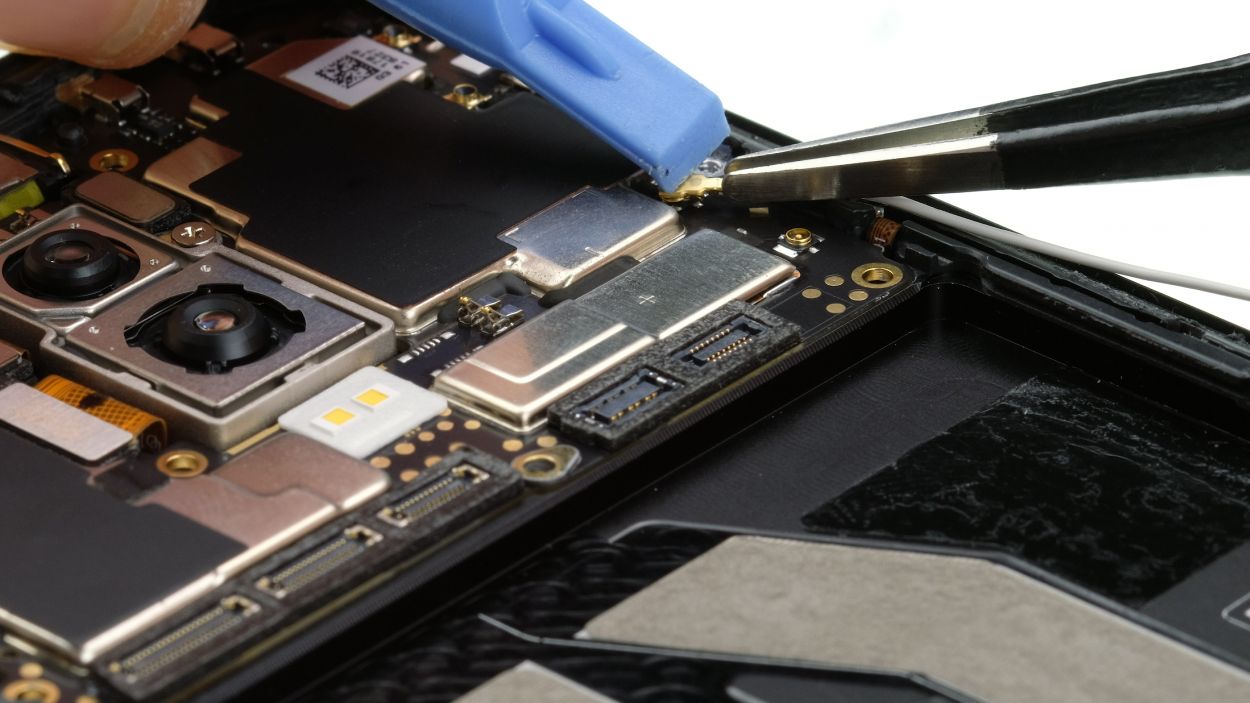
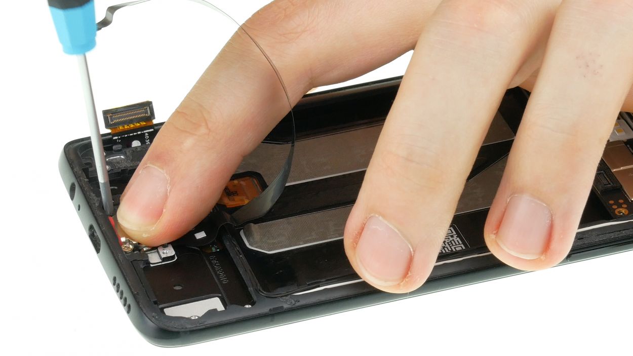
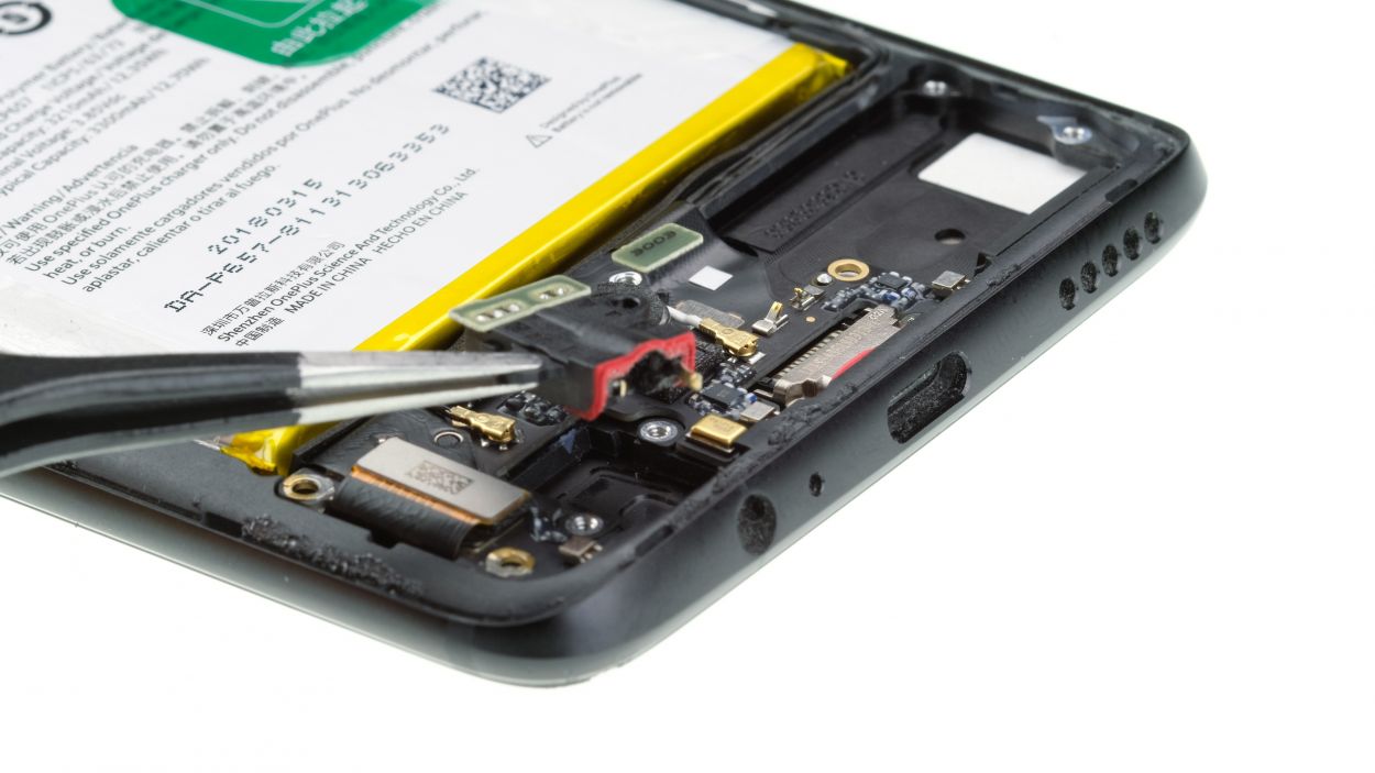
– Gently disconnect the highlighted connector of the USB flexible cable using your trusty Pry Tool.
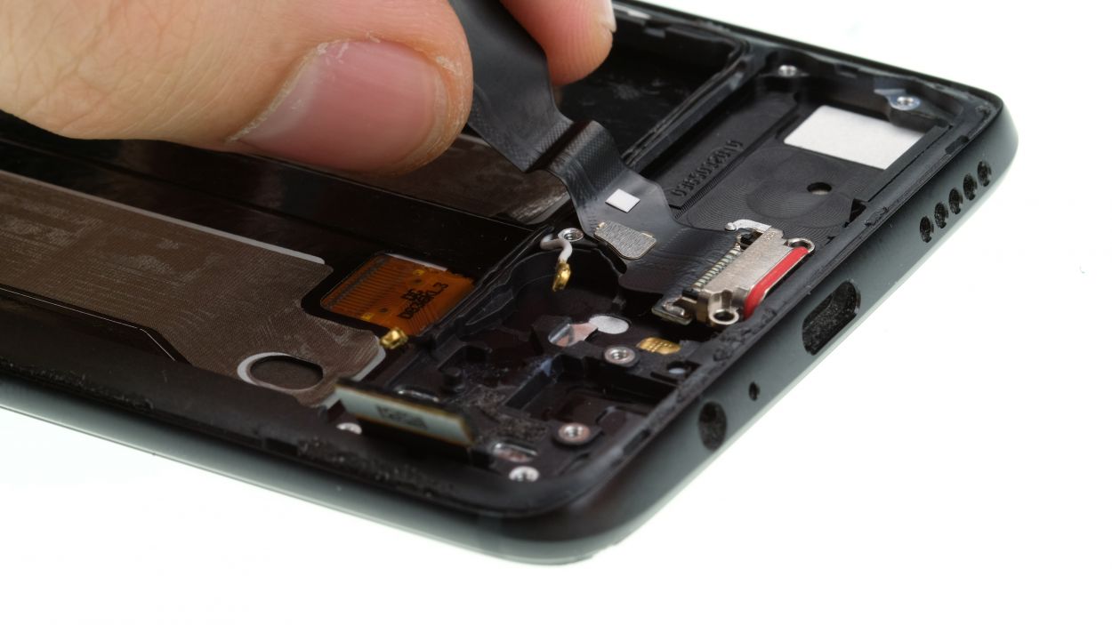
– Carefully take out the screws marked near the USB connector.
– Peel away the adhesive foil that’s snugly holding the flex cables in place.
– Remove the rubber strip that’s keeping the flex cables attached to the edge.
– Now, with a steady hand, you can start to gently pull the flex cable out of the case, one at a time.
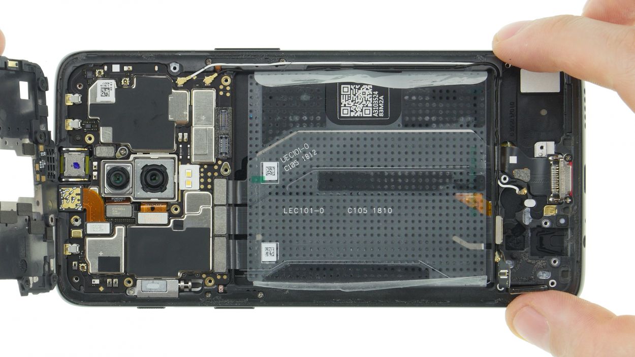
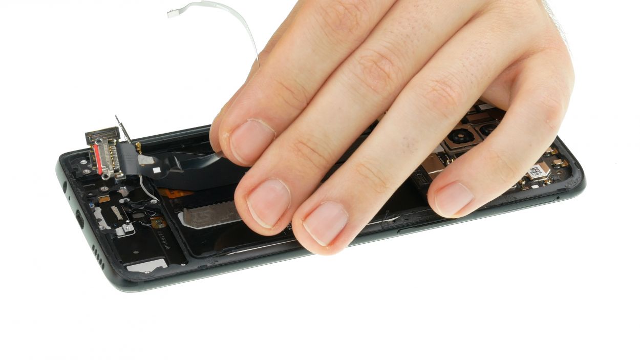
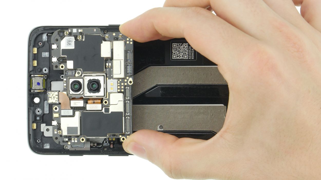
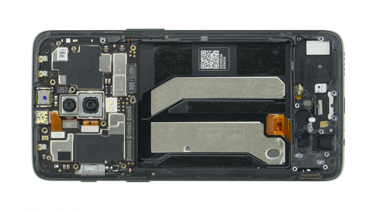
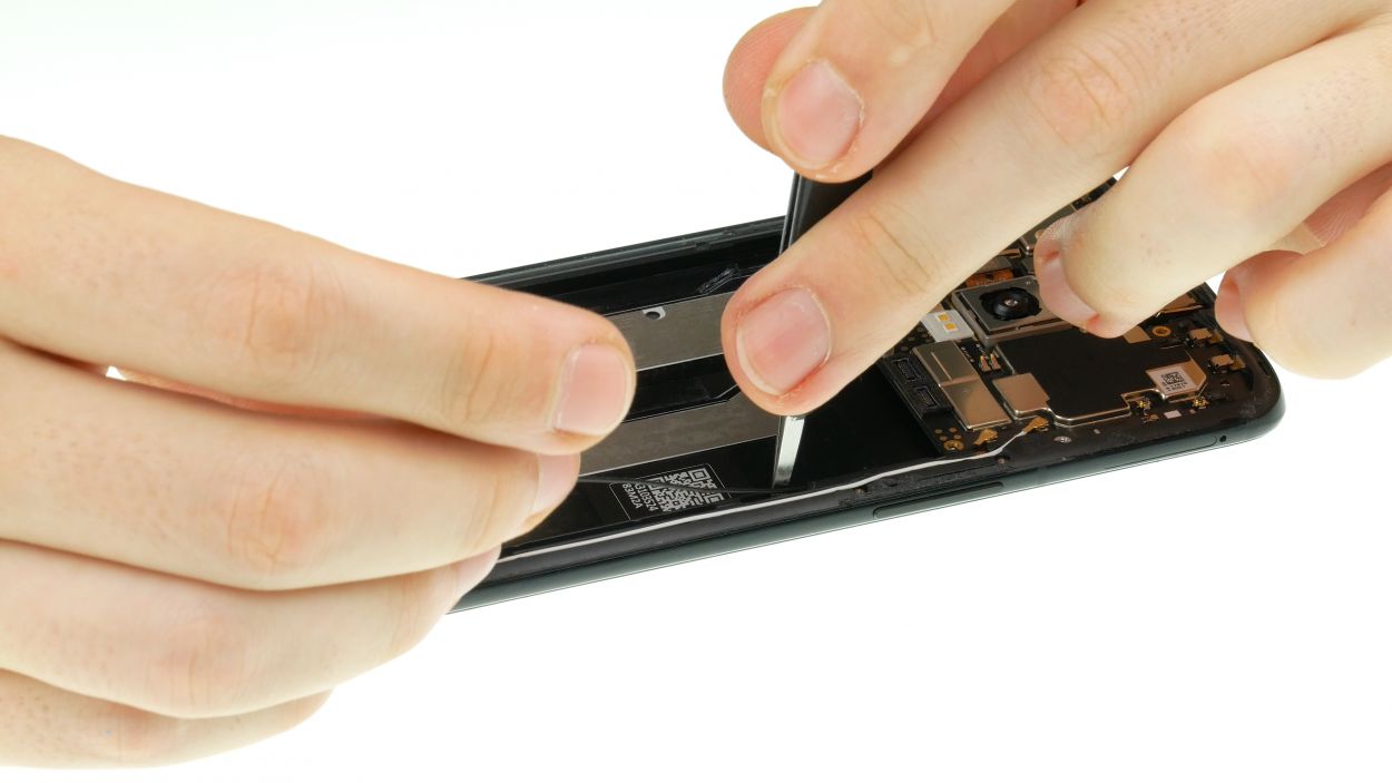
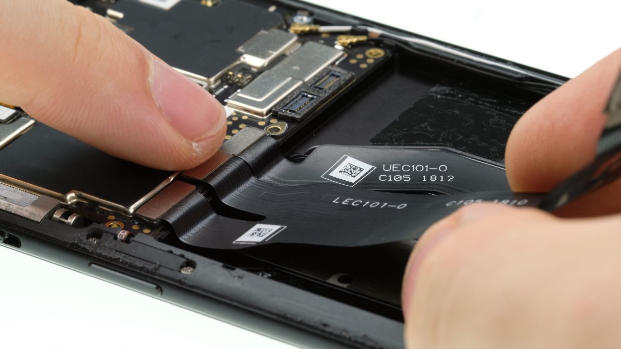
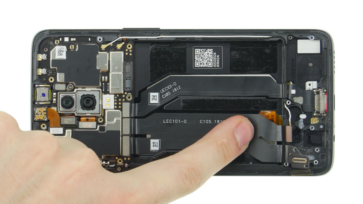
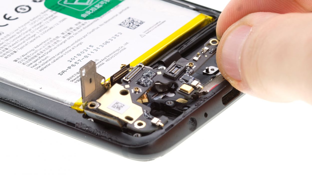
Step 13
1 × 3,0 mm Phillips
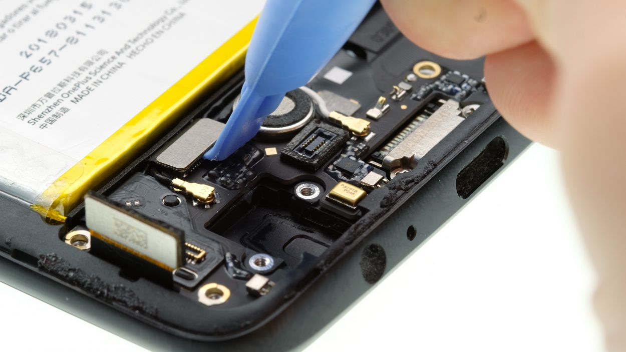
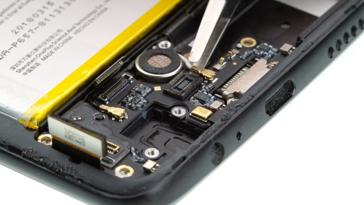
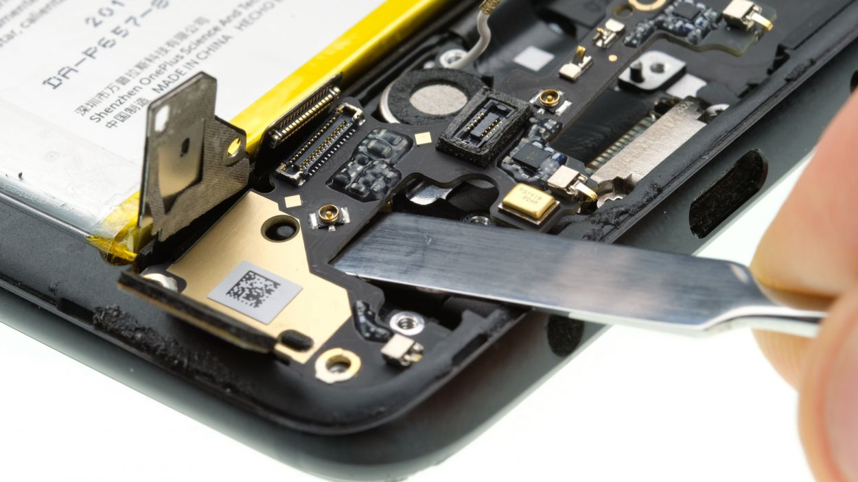
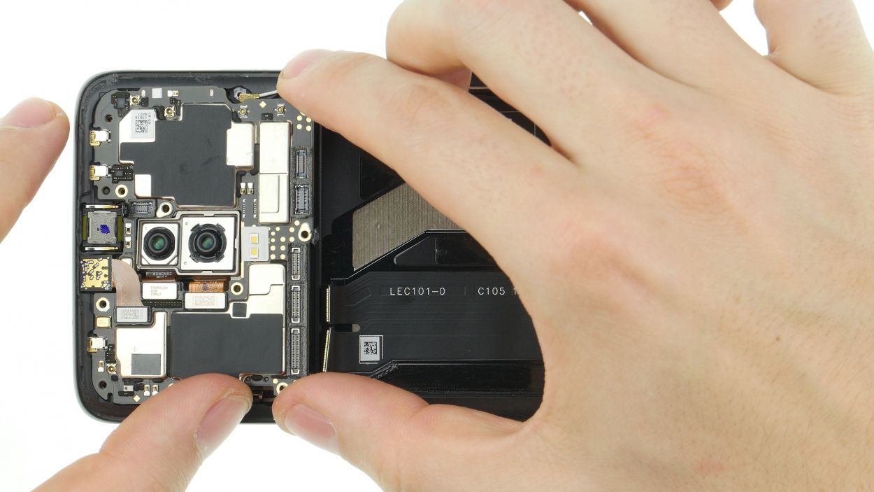
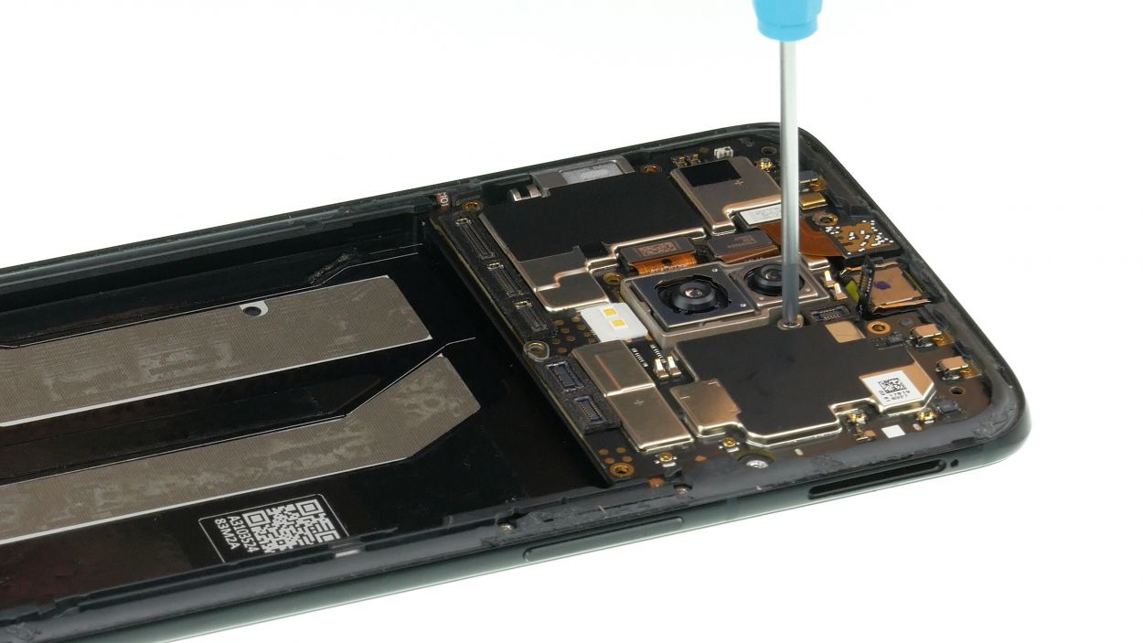
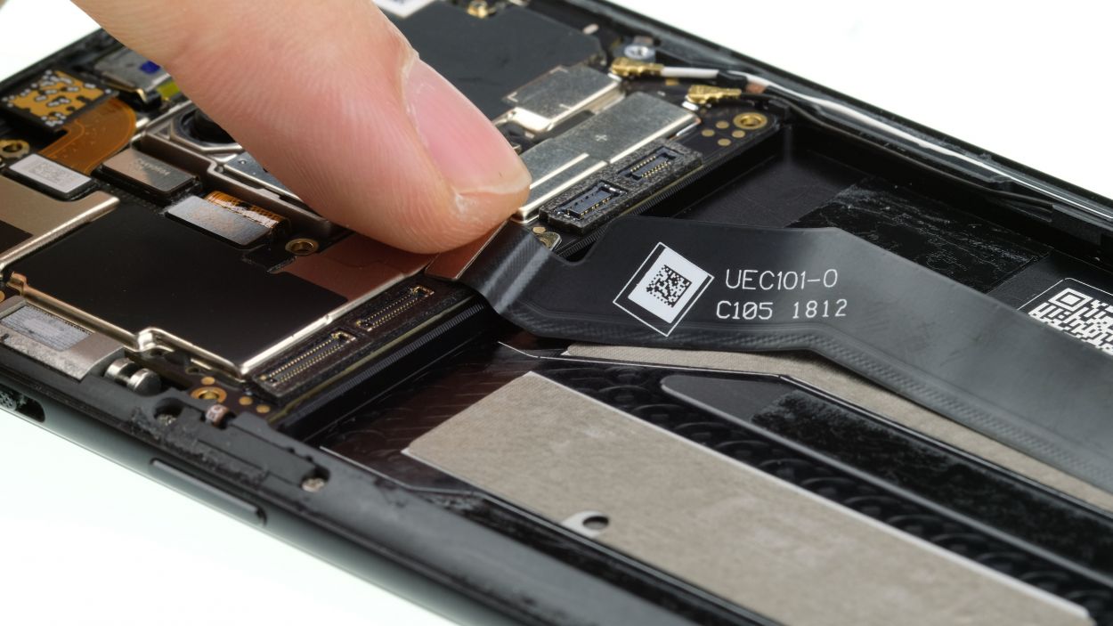
– Kick things off by loosening that handy Phillips screw holding down the mainboard.
– Next up, unplug all those connectors from the mainboard.
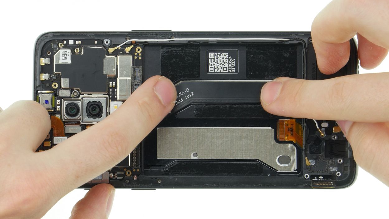
– Gently twist your tweezers to disconnect the antenna connectors—just remember to treat those sockets with care!
– Shift all cables to the side to make room for your mainboard extraction.
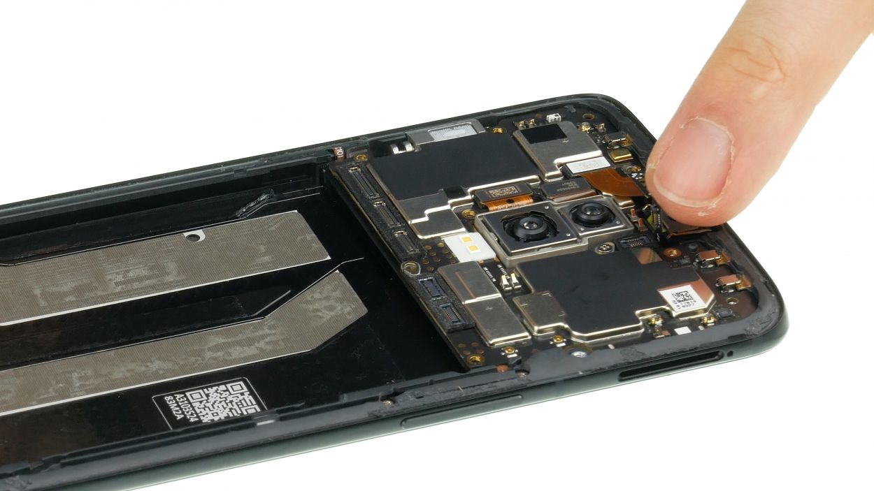
– And just like that, you can lift the mainboard out of the device!
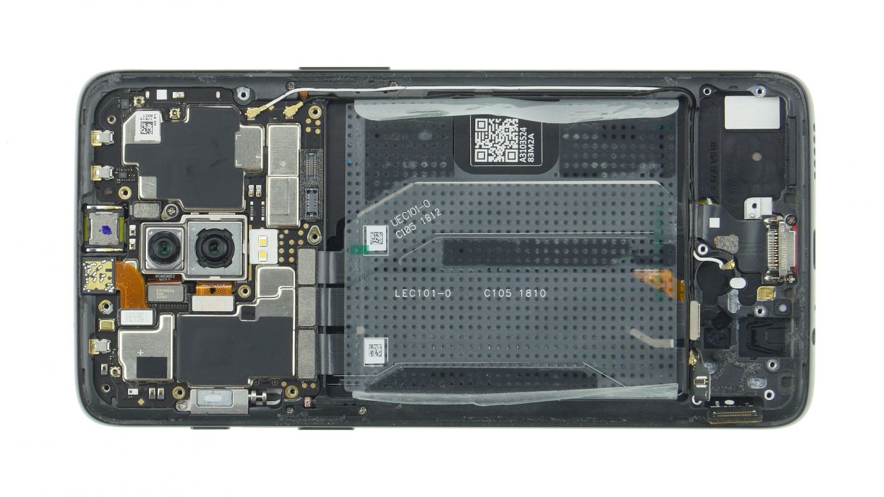
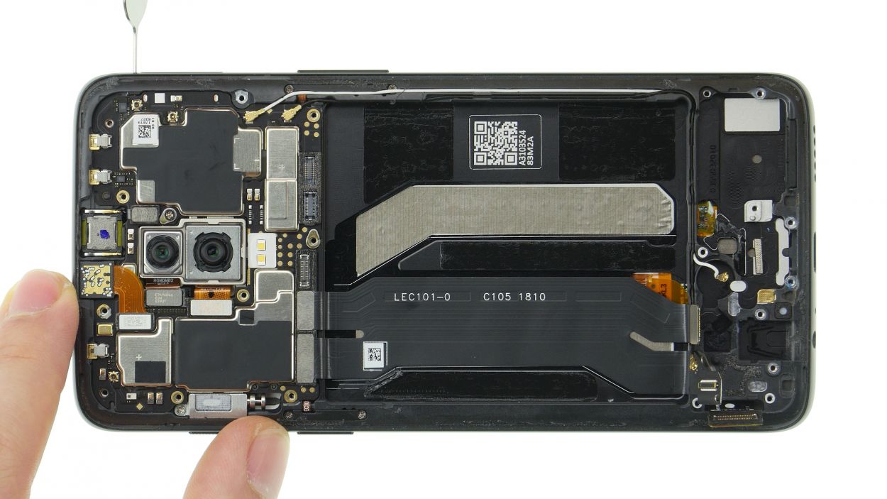
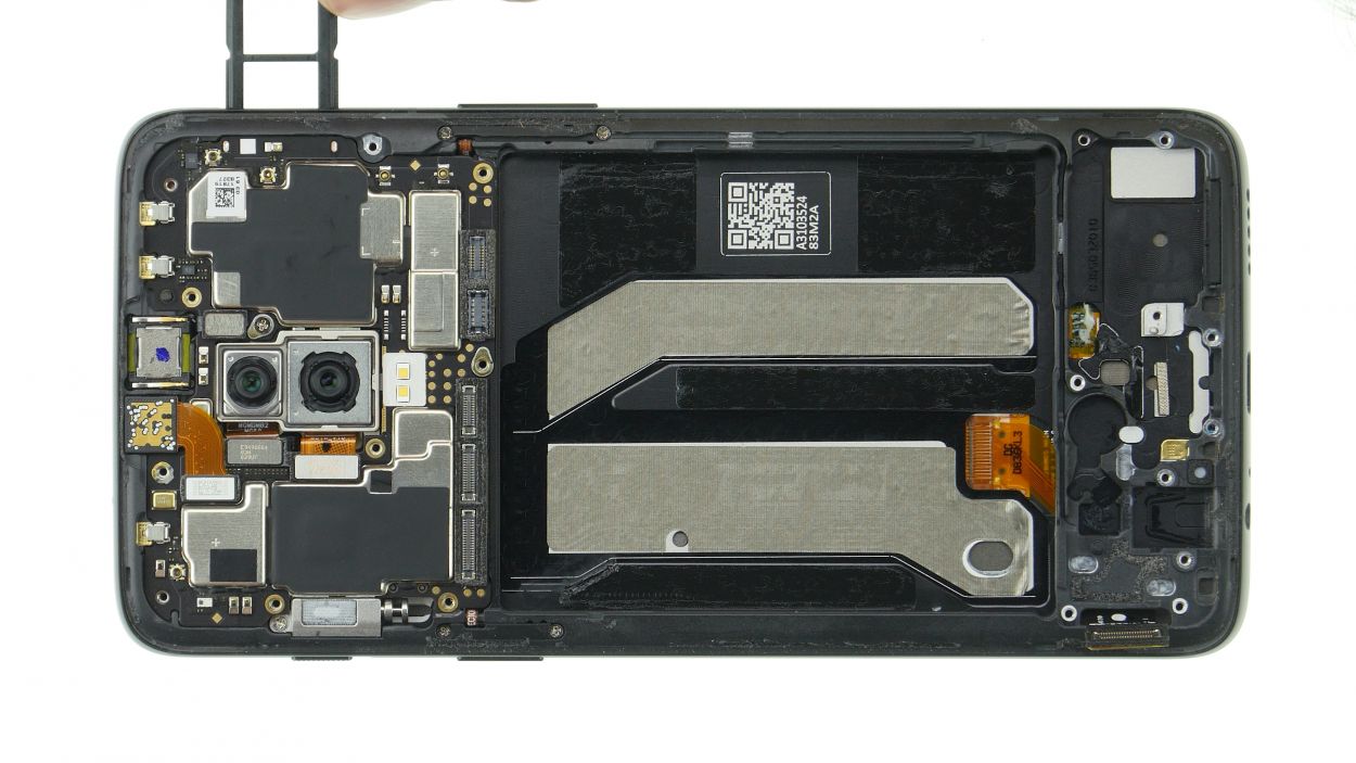
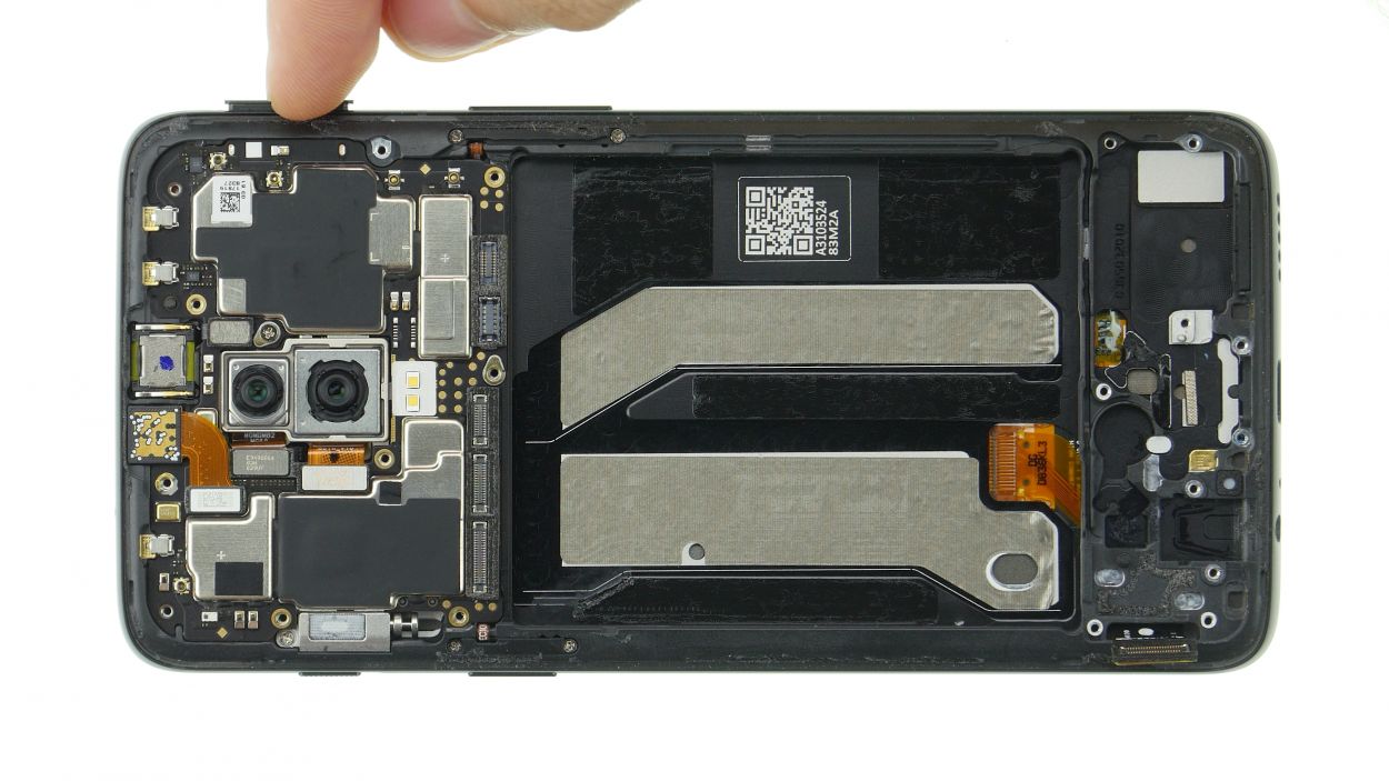
Step 14
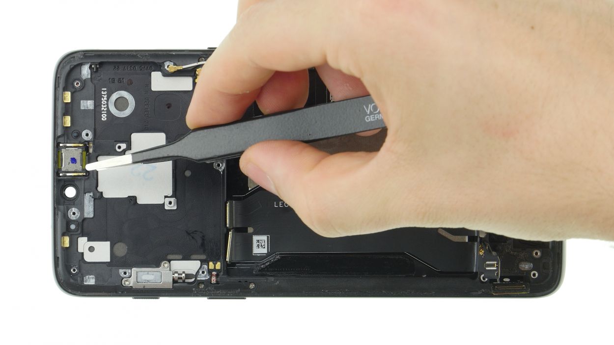
Take care not to scratch the sensitive front side.
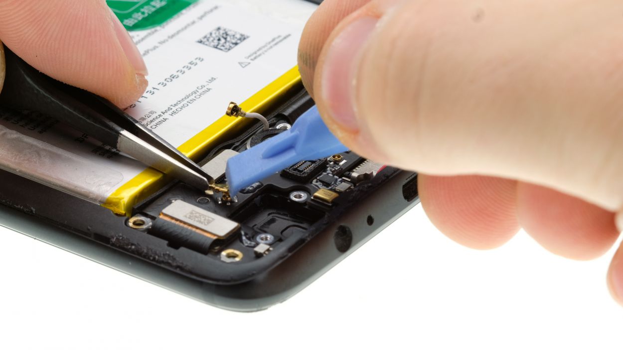
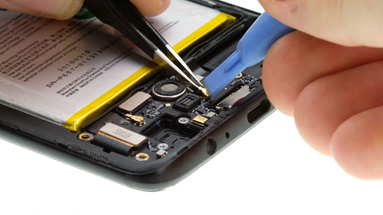
– Give the earpiece a gentle wiggle to loosen it from its socket using a flat tool. Once it’s loose, go ahead and carefully remove it from your device.
– Should you encounter any difficulties, feel free to schedule a repair
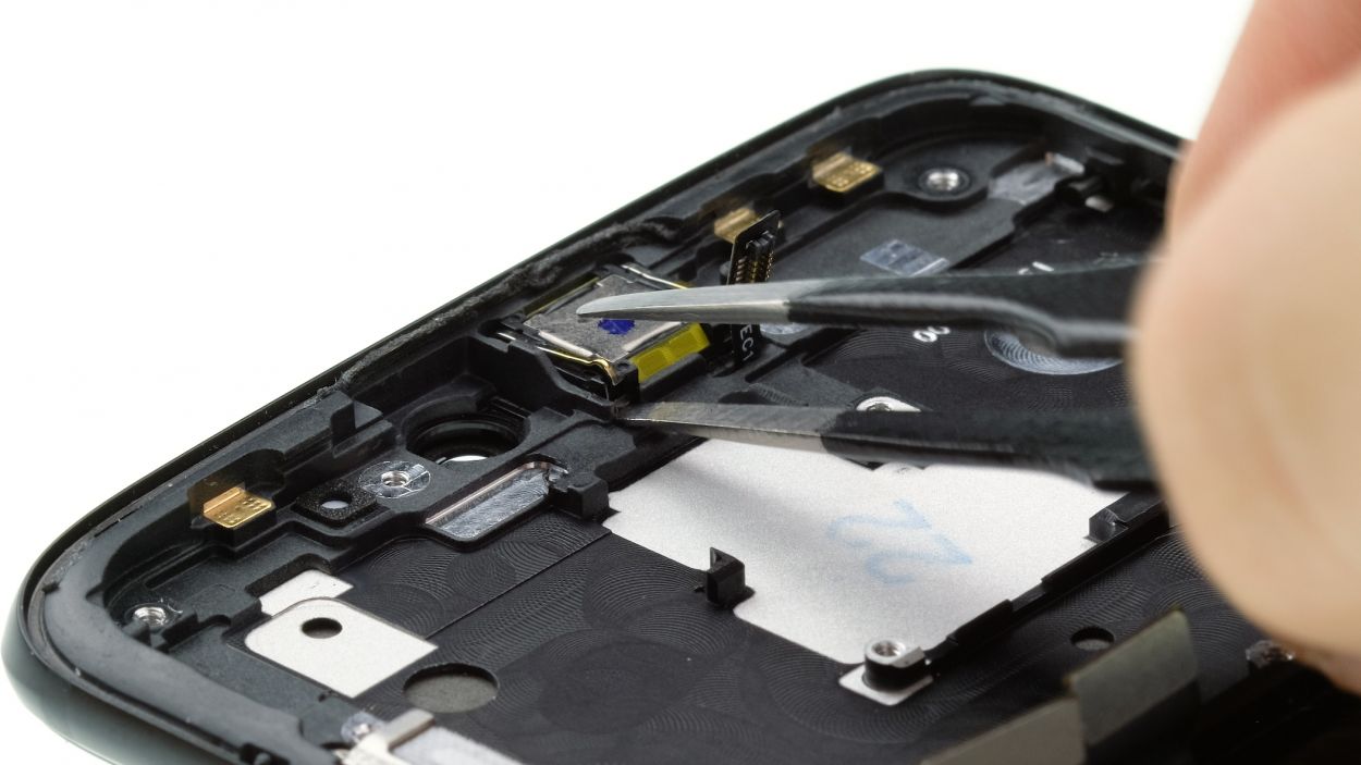
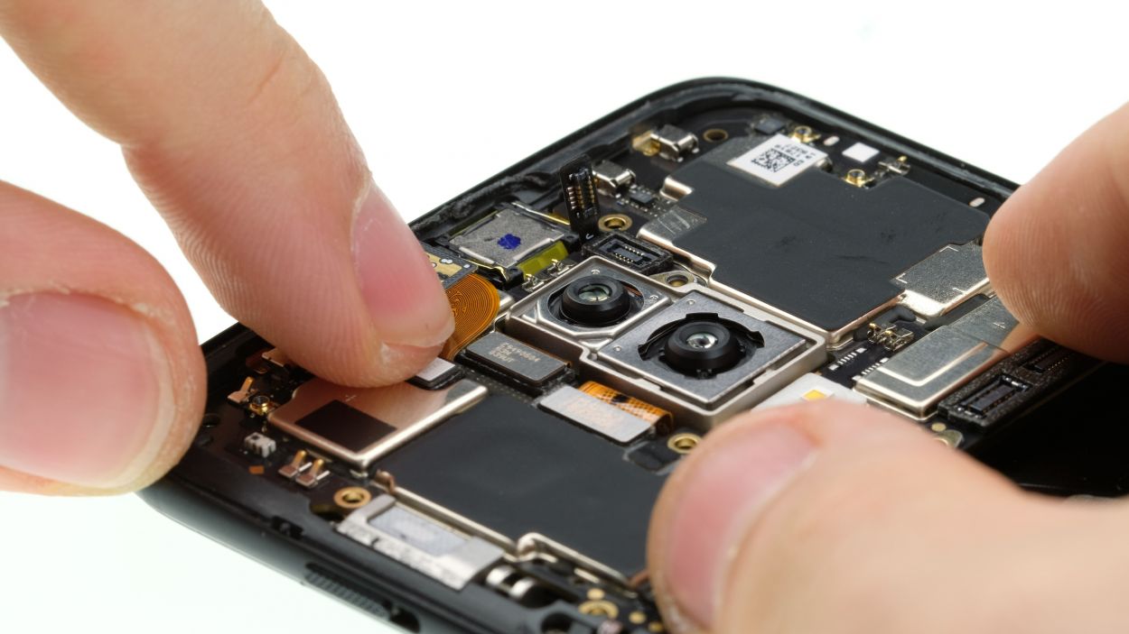
Step 15

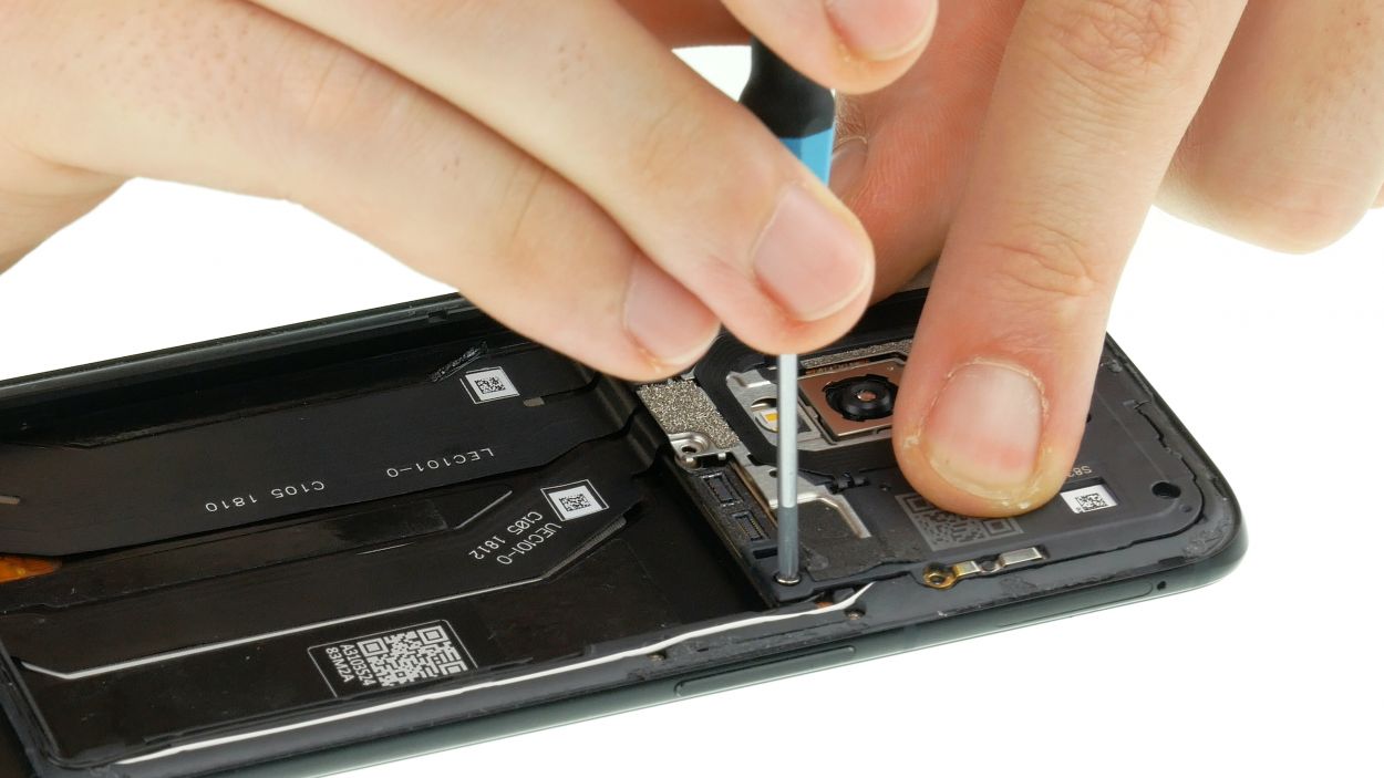
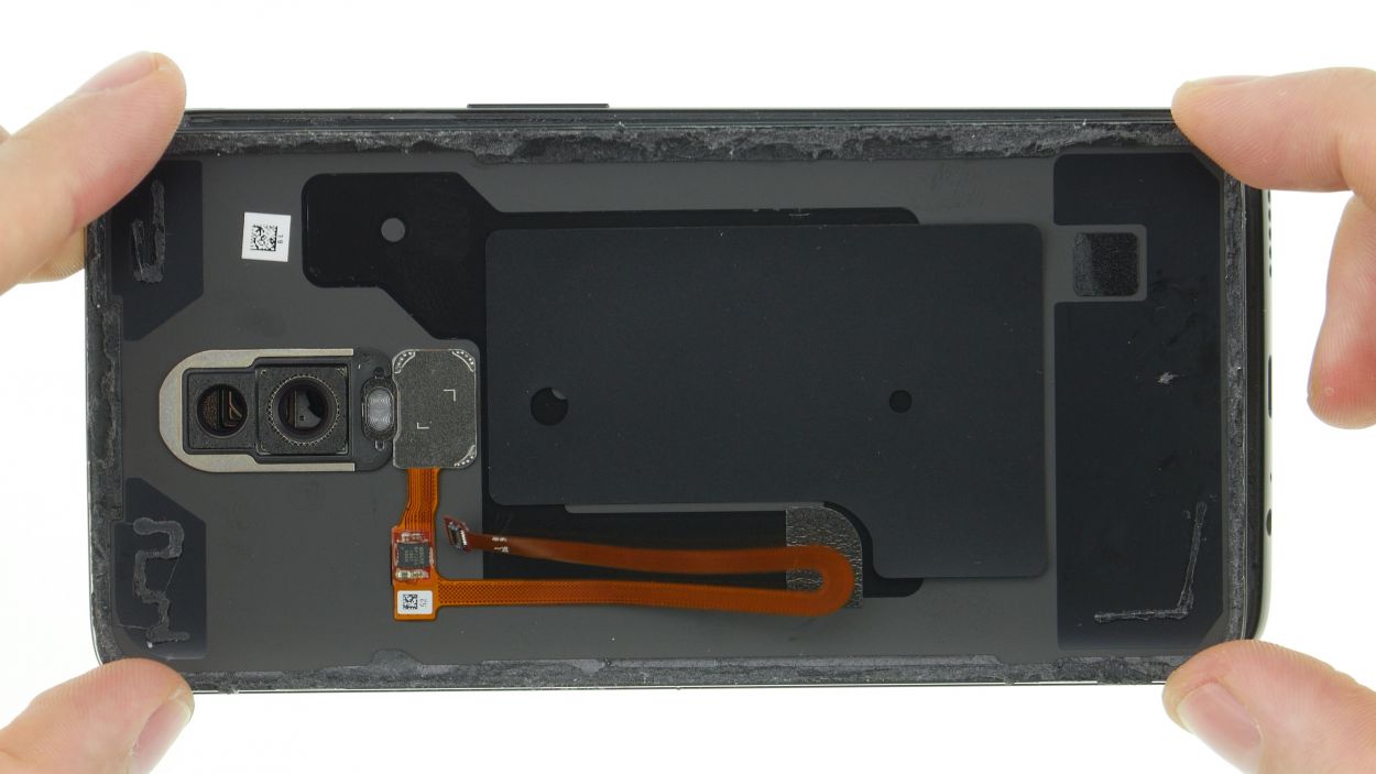
– Get a peek at the damaged area! You should see a teeny opening in one corner. Grab a super-thin tool and pry it open. Think of it like opening a present!
– Now remove the sensor. Easy peasy!
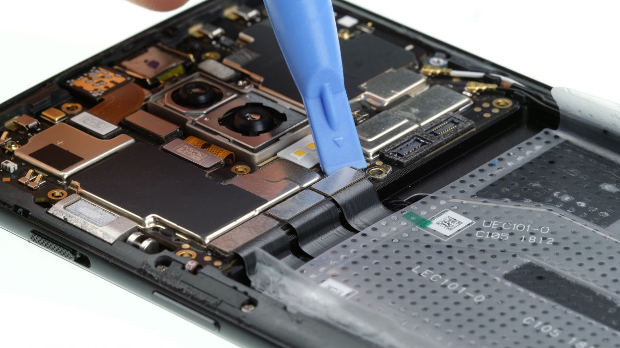
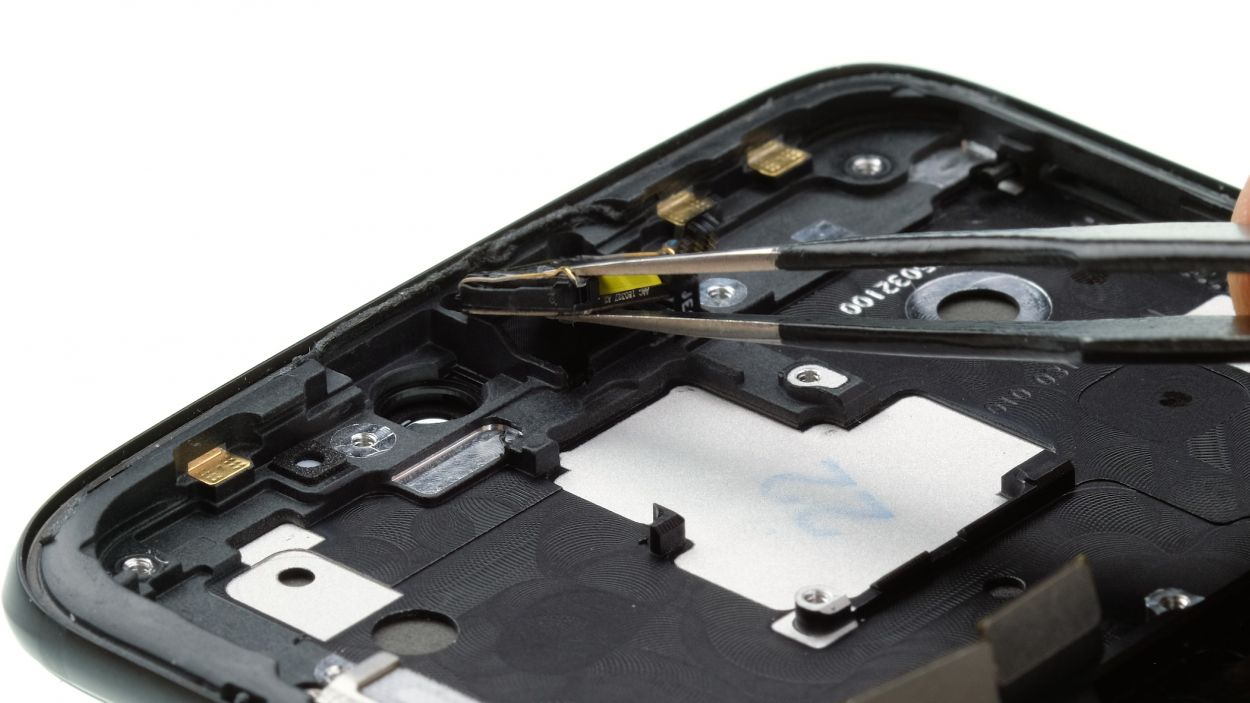
Step 16
– Gently warm up that stubborn display cable. A little heat goes a long way!
– Carefully coax the Flex cable out of the device. It’s a delicate dance; take your time!
Step 17

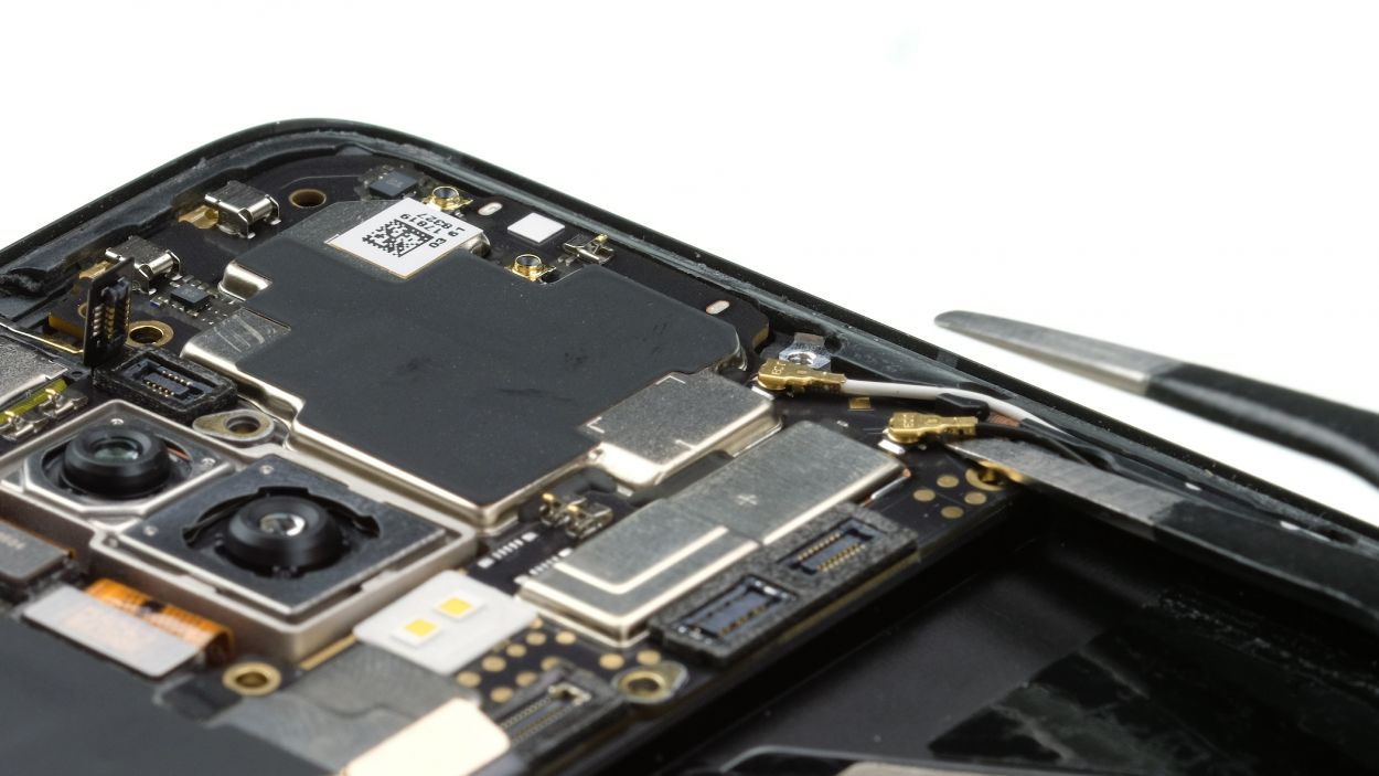
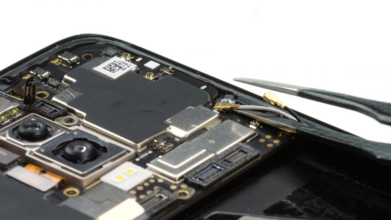
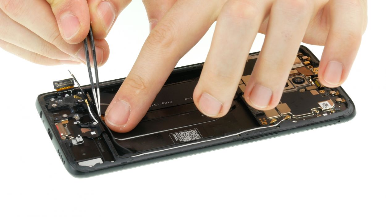
– Step 1: Time to get funky with that coaxial antenna! Gently pull it out of its cozy little home and let it shine!
– Step 2: Now, let’s give that white antenna some love. It’s been stuck in its guide, but we’re about to set it free. Carefully take out the lever and coax it out – no drama, no stress!
Step 18
Standby Button
Volume Buttons
Mute
SIM Pin
Don’t forget to snag the tiny SIM pin nestled in the upper right corner of the display if it’s absent from your spare parts. Keep it close; it’s essential for your repair journey!
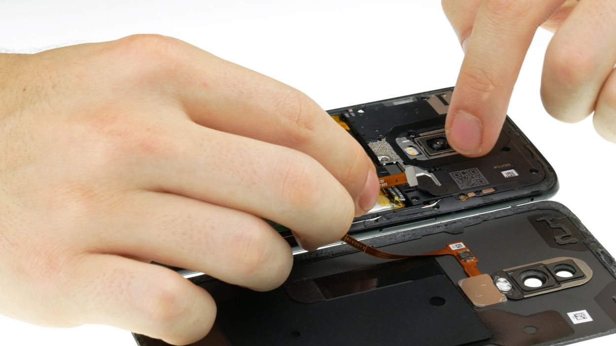
– Take a moment to compare your new spare part with the old display. Make sure to check if there are any tiny components you need to transfer.
– For instance, look out for those little flex cables for the standby and volume buttons, the shiny piece for the mute switch, or the SIM pin.
– If you spot any of these parts that need to move over, gently remove them from the old display and pop them into the new one.
Step 19
– Slide that proximity sensor right into its cozy spot.
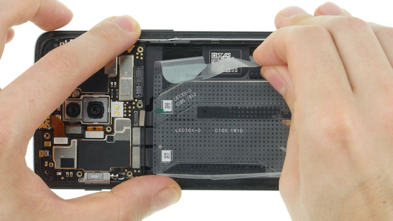
– Start by tackling those pesky larger adhesive leftovers and peel off the display’s foil.
Step 20
Time to get those spring contacts in line! Let it ride downwards, yeah! No pressure back.
– Pop that earpiece into its cozy little spot and give it a good press to make sure it sticks like a champ!
Step 21
1 × 3,0 mm Phillips
– Gently place the motherboard into the device, giving it a light press. Just make sure that the front camera is snug in its spot!
– Secure the mainboard with the trusty Phillips screw—it’s like giving it a warm hug.
– Connect the proximity sensor connector and you’re on your way!
Step 22
Don’t freak out if the SIM holder isn’t co-operating! If it’s stuck, chances are your mainboard isn’t quite settled. Just gently push it into place and you’re good to go. If you encounter some troubles, you can always schedule a repair.
– Pop your SIM and SD card into their cozy little holder and gently slide it back into your device. It’s like tucking them in for a good night’s sleep!
Step 23
– Now put the two antenna cables back into the device.
– Start with the white cable and connect it to the mainboard.
– To do this, position the contact with a pair of tweezers and press it firmly.
– Insert the antenna cable into its guide and press the silver sleeve into the clamp.
– Then connect the black antenna and lead it into the lateral guide and then over the white antenna.
Step 24
2 × 2,4 mm Phillips
USB-Flex Connector
– Slide that USB port into the cozy little slot at the bottom of the frame and give it a gentle press to snug it right in.
– Grab your Phillips screwdriver and fasten the socket with those little screws. They love a good tightening!
– Next up, connect the connector to the mainboard like a pro.
– Press down on that cable firmly, but remember to treat it gently—no wrinkles or bends allowed!
Step 25
Be cautious with those tiny contacts and connectors—they’re more delicate than they look!
– First connect both contacts on the mainboard.
Step 27
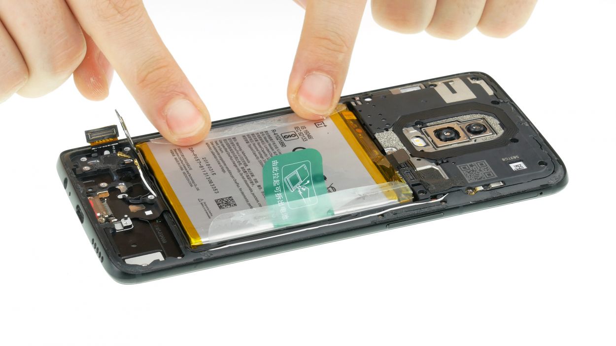
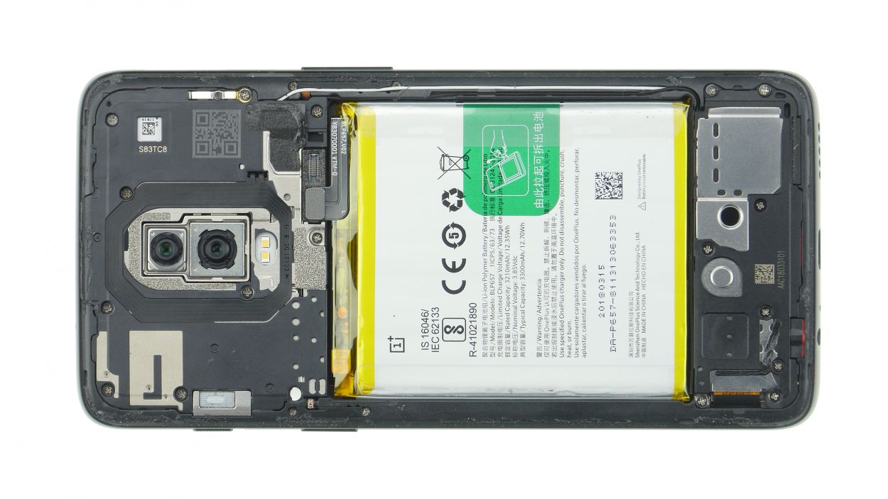
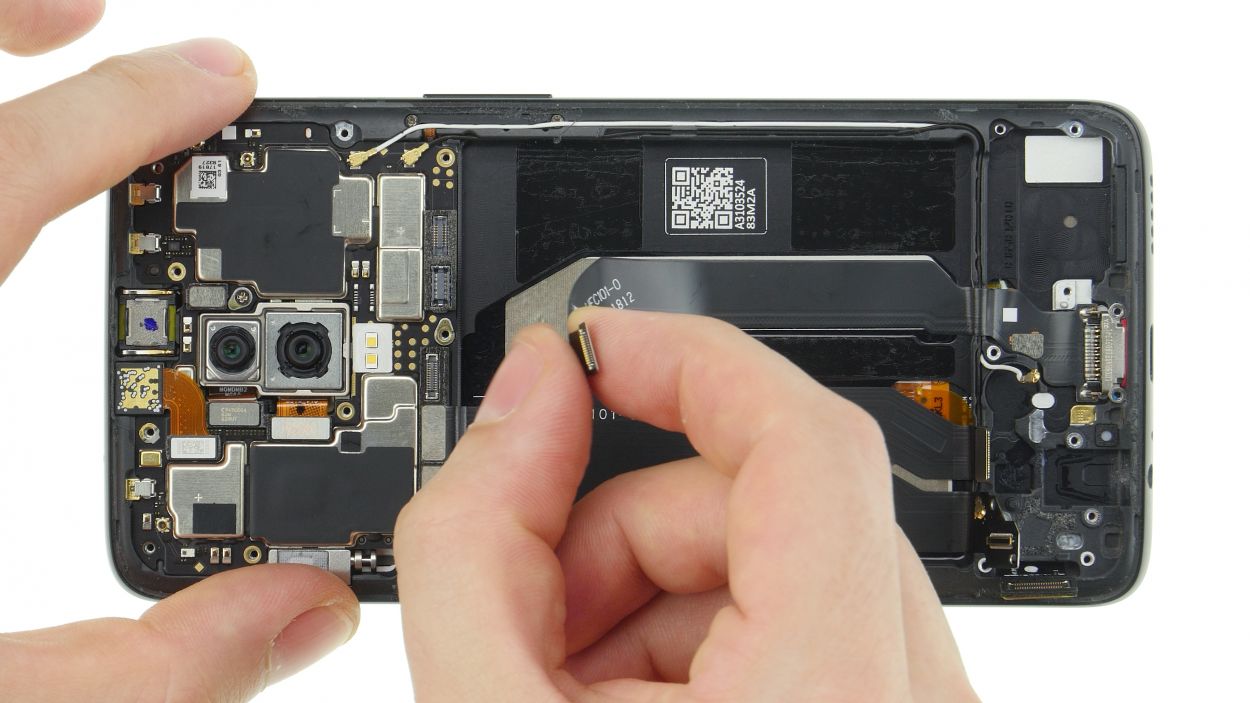
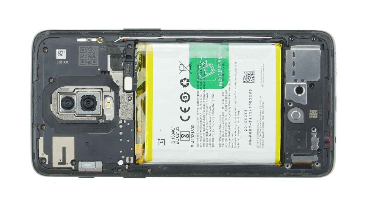
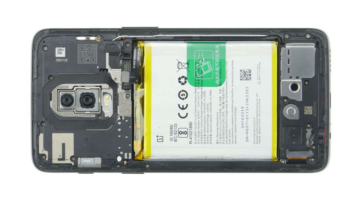
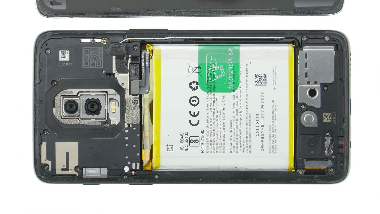
– Glad you’re taking the leap to fix it yourself! Unfortunately, our phones can’t fix themselves. First things first, slide that transparent foil back over the battery area, then gently insert the battery into its home sweet home. This will save you some serious battery-removal drama down the line!
– Sweet tease: place the battery with a little breathing room – no squeezing it against the frame or other secret components. Yep, it’s all about the air space, folks!
– Rock on! Position that battery contact right on top of its socket on the mainboard. You’re getting closer to a fully functional device!
Step 28

– Gently place the vibration motor into its cozy little spot.
– Double-check that the contacts are snugly in position.
– Give the vibration motor and contacts a firm press to ensure they stick together like best buddies.
Step 29
Ensure those antenna cables are cruising along their designated paths like they own the place!
– Put the lower board in its place. Make sure it sits correctly everywhere. The small openings of the board are directly above the noses in the device.
– Put the plug of the display cable on the board. The round opening helps positioning.
– Connect the display connector and the cable to the mainboard.
– Use tweezers to connect the antenna connectors. Position the plugs directly above their socket and press them firmly with a spudger.
Step 30

– Get that headphone jack where its home is – in its place. Make sure that golden pin goes through the opening, like a needle through thread.
– Shake a leg and press that jack down good. Now plug in the connector like its a party
Step 31

8 × 3,0 mm Phillips
– Pop that speaker onto the lower edge and give it a good press until it clicks into place.
– Secure the speaker with those trusty Phillips screws and make sure it’s snug!
Step 33
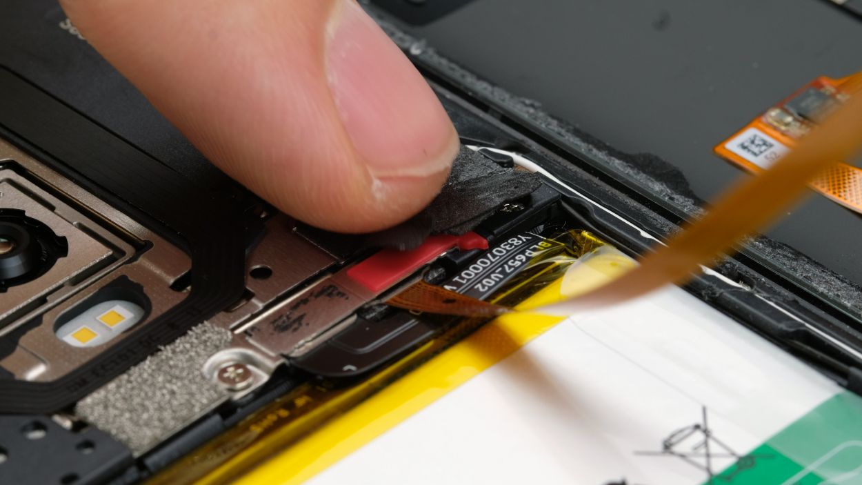
Fingerprint Connector
– Set the back cover right next to your device, ready for action!
– Carefully lay the fingerprint sensor cable over its mainboard connection and give it a snug fit.
– Now, pop on the cover with that stylish red rubber piece and seal it up with the black glue.
Step 34
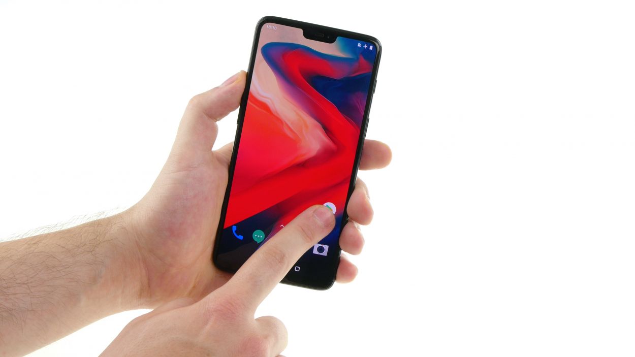
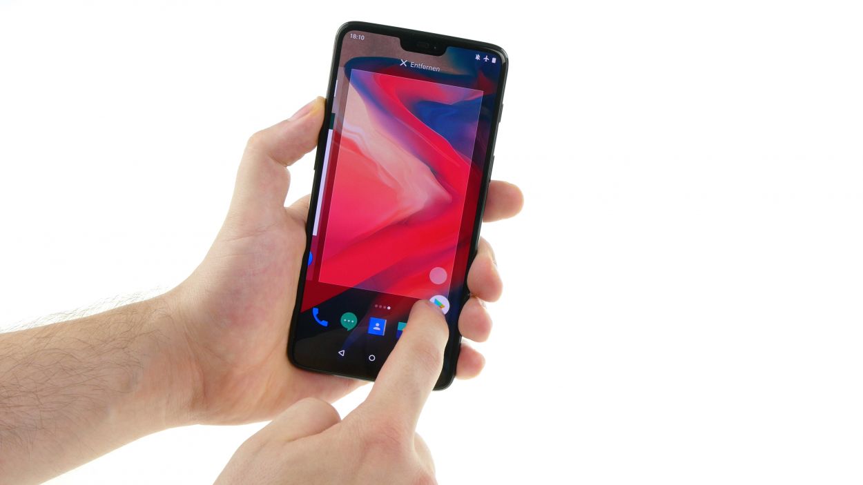
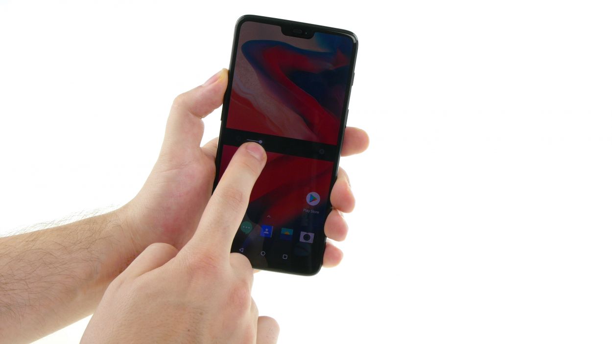

– First things first, power up your device and give that screen a good look!
– Next, slide an app along the edge and zigzag it across the display to ensure the touchscreen is responding like a champ at every corner.
– Don’t forget to check out the brightness levels—test both the dimmest and the brightest settings.
– Time to put those cameras to the test! Check out the front and rear cameras along with the flash.
– Make a call to a friend and see how the microphone and earcup are doing.
– Finally, mute your phone and give that vibration motor a little workout!
Step 35

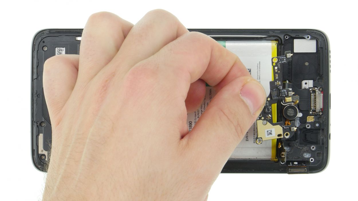
Give your device a little TLC by sandwiching it between a couple of books and letting the glue work its magic for about an hour. Patience pays off!
– Time to warm things up! Gently heat the device to loosen that stubborn back cover glue.
– Press the back cover snugly onto the device frame. You got this!


