DIY Guide to Replace Samsung Galaxy S21 5G Screen and Battery Assembly
Duration: 45 minutes
Steps: 50 Steps
totally
deplete the battery
Hey there! Ready to tackle replacing the screen and battery assembly on your Samsung Galaxy S21? This guide is all about that screen and battery duo. Just a heads up – this assembly includes the screen, battery, and frame all in one handy part. Make sure you’ve got the correct piece before diving in. If your battery is acting a bit puffy, take the necessary precautions. Before you start taking your device apart, make sure that battery is completely empty. This helps lower the chance of any unexpected hot situations if the battery gets bumped during the repair. Remember: Keeping that water resistance post-repair will depend on how carefully you reapply the adhesive, but your device will sadly lose its IP (Ingress Protection) rating. Keep an eye out for any slight differences in the images you see – they won’t throw off the guide overall. Get ready to rock this repair like a pro!
Step 1


Oops! If you happened to poke the SIM eject tool into the microphone hole, no need to stress! It’s highly likely that the microphone is just fine.
– Pop a SIM eject tool, bit, or straightened paper clip into the SIM card tray hole located on the bottom edge of your device.
– Gently press the tool into the tray hole to coax out the SIM card tray.
– Liberate the SIM card tray and bid it adieu.
Step 2

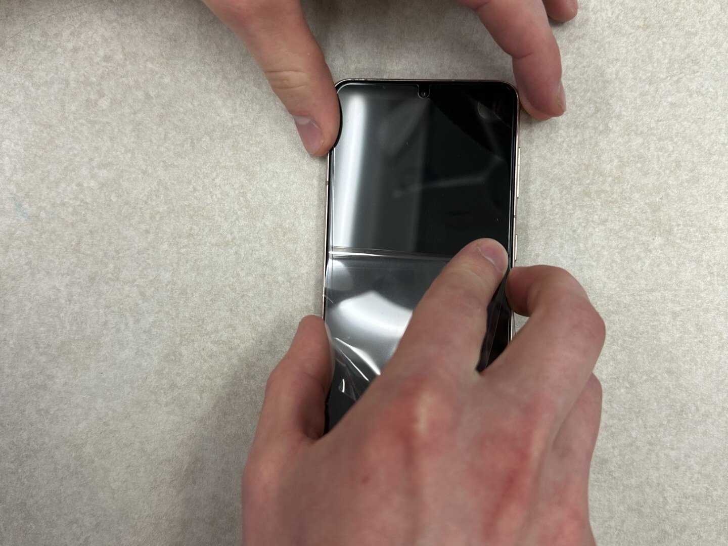
Make sure to power down your phone completely before diving in.
– Warm up your iOpener and give a cozy two-minute hug to the bottom edge of the back cover.
Tools Used

Step 3


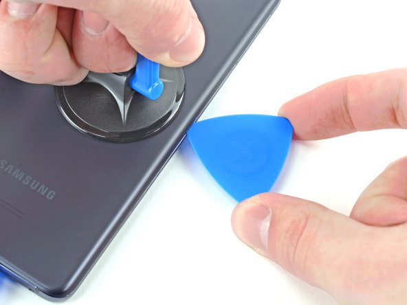
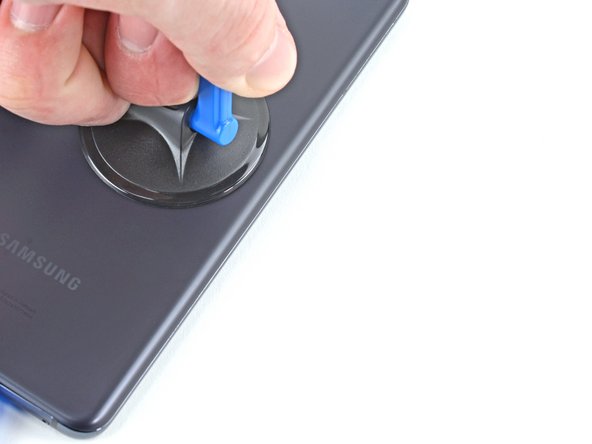
– Grab a suction cup and stick it to the back of your phone, aiming for the center of that bottom edge.
– Give that suction cup a firm pull upwards to open up a little gap between the back cover and the frame—nice and steady!
– Now, slide an opening pick into that gap you’ve created.


Step 5

– Get that heated iOpener groovin’ on the back cover’s left edge for a cool two minutes.
Tools Used
Step 6


– Stick a suction cup on the back of your device, aiming for the center of the left edge.
– Give that suction cup a good, firm tug to separate the back cover from the frame.
– Slide an opening pick into the gap you’ve created.
Step 7


– Gently glide an opening pick along the left edge, making your way to the bottom left corner to slice through that pesky adhesive.
– Keep the pick in place to stop the adhesive from sealing back up. You’re doing great!
Step 8

– Warm up your iOpener and give the back cover’s right edge a cozy two-minute hug.
Tools Used
Step 9

– Grab a suction cup and stick it onto the back of the phone, aiming for the sweet spot near the center of the right edge.
– Now, give that suction cup a firm pull upwards – we want to make a little wiggle room between the back cover and the frame.
– Slide in an opening pick into that gap you just created, and let’s keep moving forward!
Step 10


– Gently slide an opening pick back and forth along the right edge of the back cover to help sever the adhesive bond.
– Keep the pick in place to stop the adhesive from re-sticking like it just got a second chance.
Step 11


Feel free to tackle each corner with confidence, just skip the top-left since that’s where your rear-facing camera hangs out.
– Swing that right-edge opening pick around the top-right corner of your phone like a pro!
Step 12


– Gently slide that top pick right up next to the camera shell for a snug fit.
– Now, give the left-edge pick the same loving treatment!


Step 14


If this approach isn’t doing the trick, just glide over to the next step for a plan B; otherwise, feel free to skip ahead.
– Give the back cover a little twist to the left, just like unscrewing a pickle jar lid but way easier!
– Pop in an opening pick between the camera shell and the frame. Easy peasy!
Step 15


– Gently slide a super cool opening pick between the camera shell and the frame to totally snip the adhesive.
Step 16


– Align the tip of your trusty opening pick with your phone’s flash.
– Gently slide the pick in, keeping an eye out to steer clear of the flash’s plate.
– Carefully slice through the adhesive just to the right of the camera.
Step 17


– Get ready to show that back cover who’s boss!
– For the next step in this awesome repair adventure:
Step 18


– Grab your trusty Phillips screwdriver and get ready to tackle this! Carefully remove the five screws, each measuring 4 mm, that are holding the motherboard bracket snugly in place on the frame. You’re doing great!
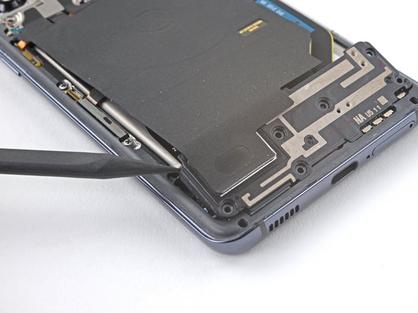
Step 19


Hold your horses! Don’t take off that bracket just yet; it’s still hanging out with the wireless charging coil.
– Grab a trusty pair of tweezers and carefully lift up and unclip that motherboard bracket from the frame. You’ve got this!
Tools Used

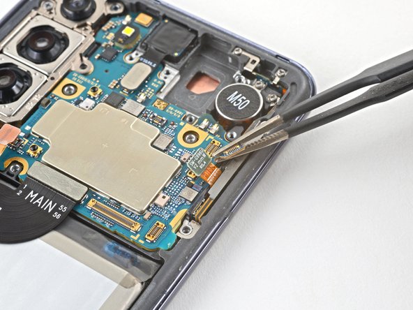
Step 20
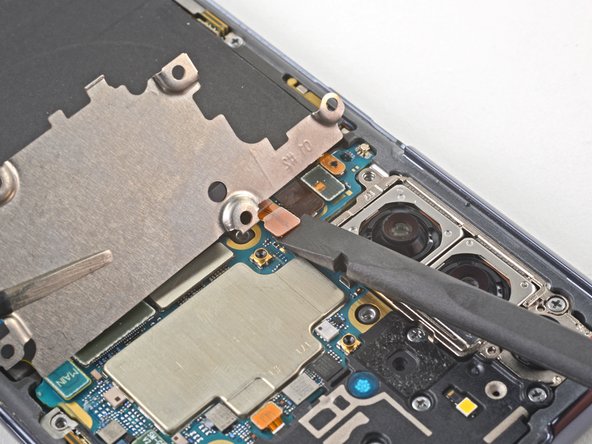

– Hey there! While you’re gently using tweezers or your fingers to hold the motherboard bracket out of the way, take your spudger and give a little nudge to lift up that battery press connector.
– When it comes to re-attaching press connectors like this gem, just make sure to align it with care and press down on one side to hear that satisfying click, then give the other side the same treatment. Remember, no pressing in the middle, keep it cool. If it’s a bit wonky, those pins might bend and that’s a no-go for your device.

Step 21
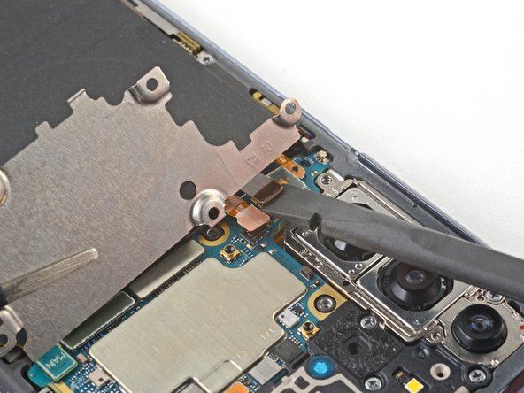

– Get that motherboard bracket out of your way by gently holding it back, then grab your trusty spudger to lift and separate the wireless charging coil’s press connector.
Tools Used
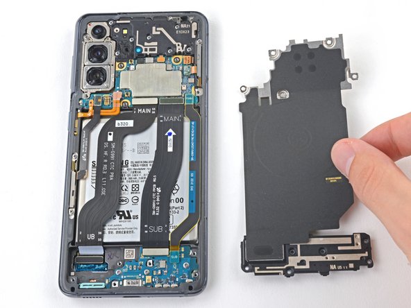
Step 22


– Grab your trusty Phillips screwdriver and let’s get to work! Start by unscrewing those six 4 mm-long screws that are holding the loudspeaker to the frame. You’re almost there – keep going!

Step 24

– Alright, tech lover! Time to get creative. Who says you can’t tinker under the hood? Unplug that wireless charging coil gizmo from its socket, if you know what we mean. Got questions? Fear not! We’re here to help, so don’t hesitate when you need some extra tricks. Oh, and if you need help, you can always schedule a repair!
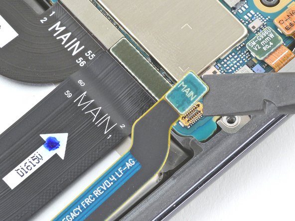
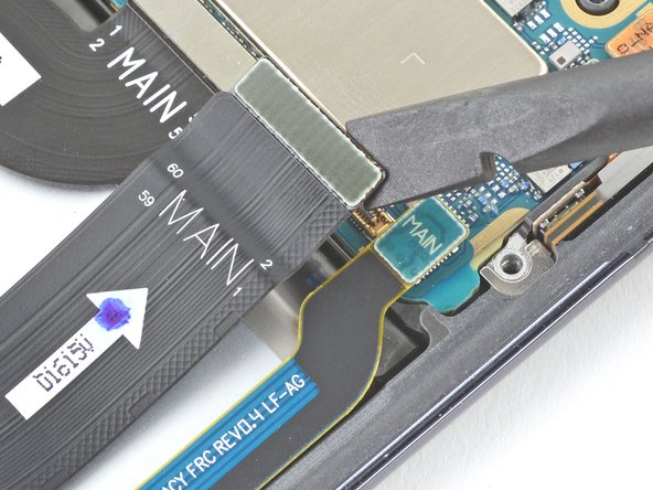
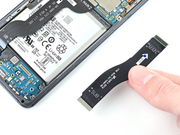
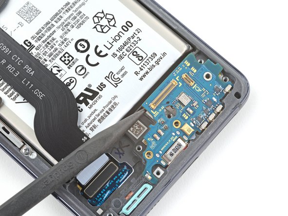
Step 25


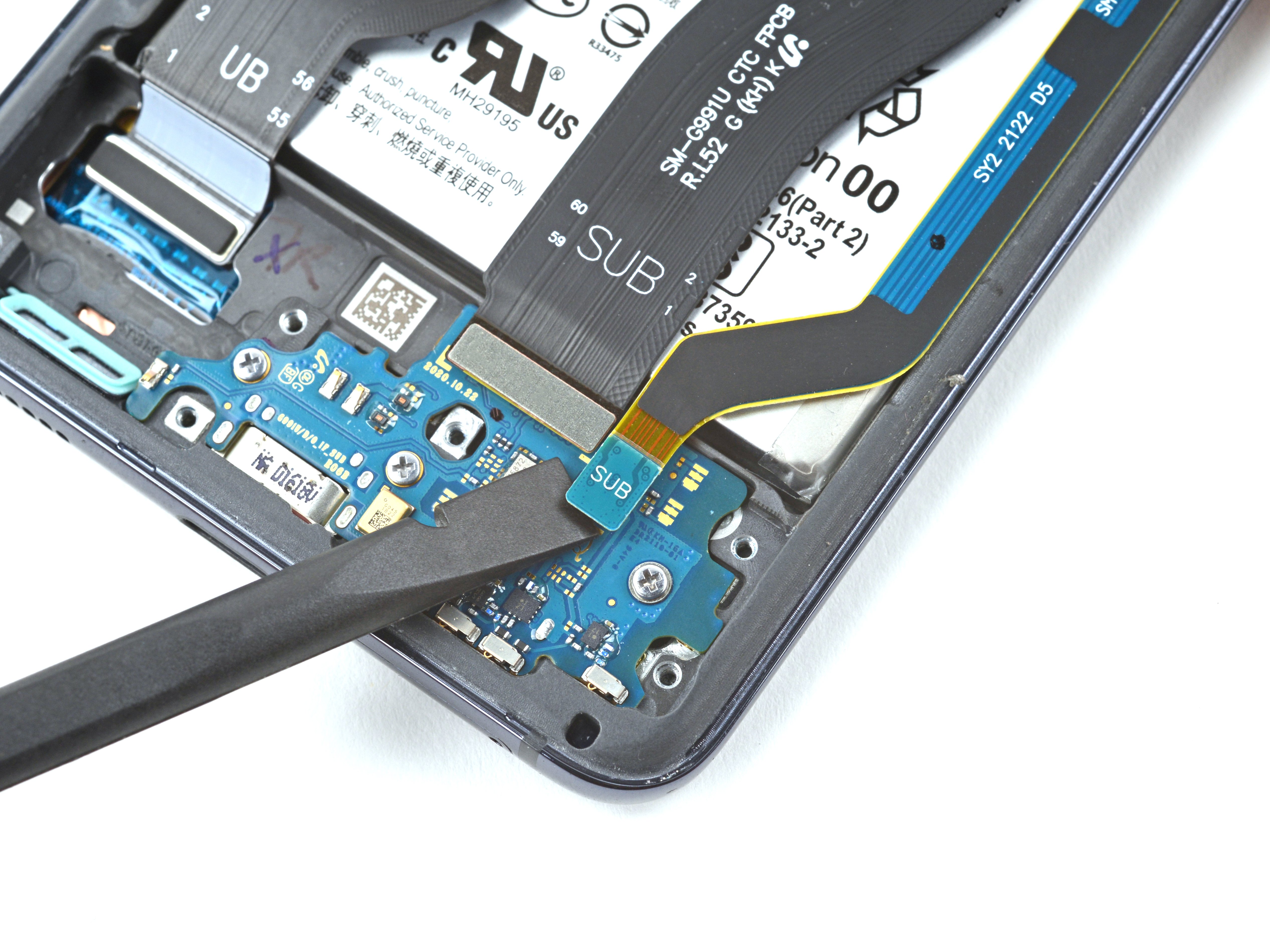
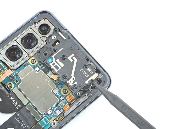
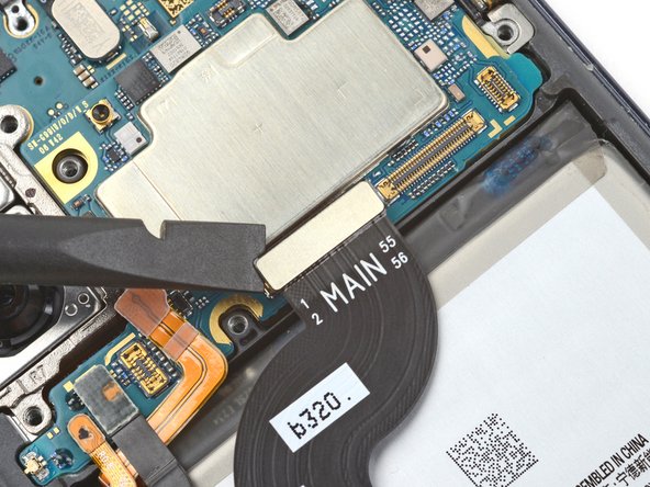
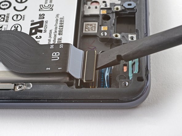
– Time for some major connective action! Use the flat end of a spudger to embark upon an adventure and disconnect the primary interconnect cable’s press connector. If you need help, you can always schedule a repair.
Tools Used


Step 29
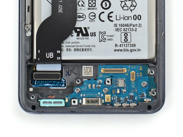

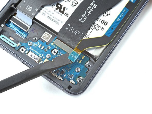
– Grab your trusty Phillips screwdriver and gently unscrew the three 3.5 mm-long screws that are keeping the daughterboard cozy in the frame. You’re doing great!


Step 31

– Grab your trusty spudger and gently pry up to disconnect that earpiece speaker cable’s press connector. You’ve got this!
Tools Used
Step 32


– Grab your trusty Phillips screwdriver and get ready to tackle this! Remove the seven 4 mm-long screws that are holding the earpiece speaker snugly onto the motherboard. Let’s get that speaker free!
Step 33

– Let’s dive in and start the magic! Gently slide your trusty spudger into the cozy gap between the right-most edge of the earpiece speaker and the phone.
– With the finesse of a magician, use the spudger to gracefully pry up and set free the clips hugging the earpiece speaker in place.
– Now, with precision and care, either wield your tweezers like a pro or simply use your fingers to delicately remove the earpiece speaker.

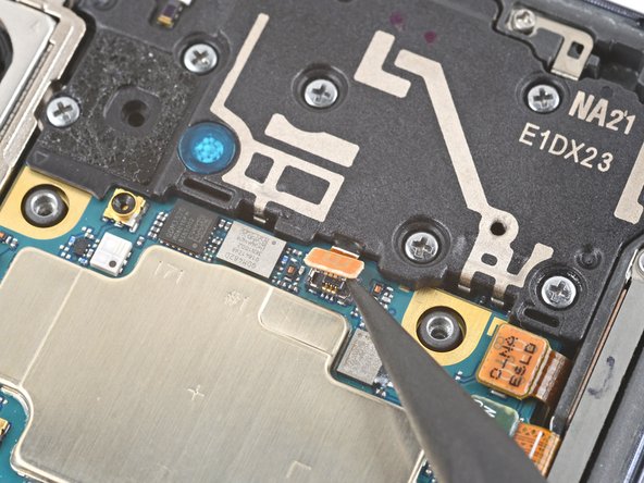
Step 35


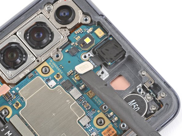
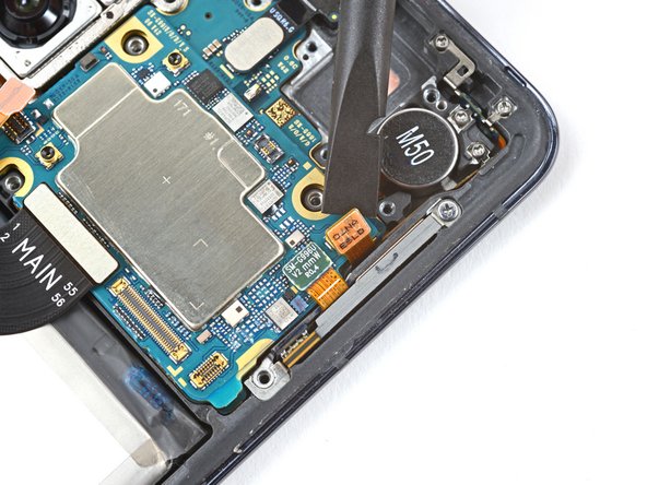
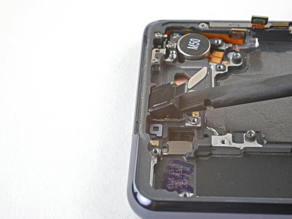
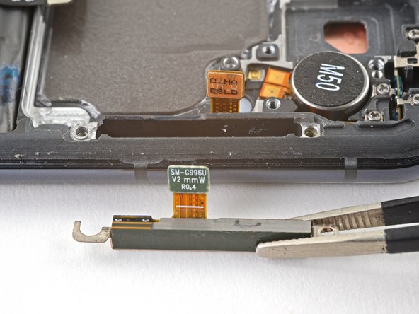
– Grab that trusty spudger and gently lift up to disconnect the press connector of the left 5G mmWave antenna cable. You’ve got this!
– Now, do the same for the power button cable’s press connector. Easy peasy!
Tools Used
Step 36

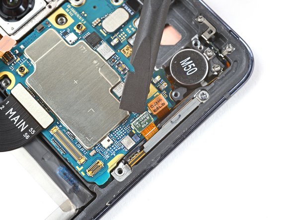
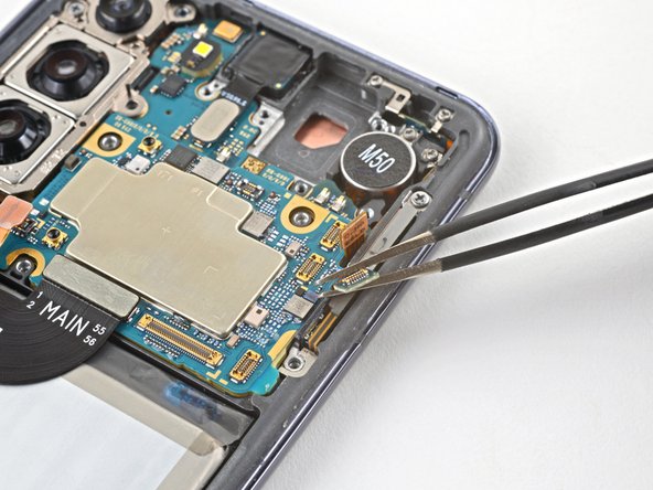
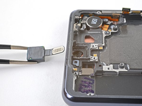
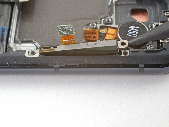
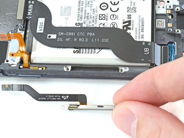
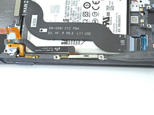
Be gentle when moving those cables around. No folding or sharp bends, or they might break!
– Hey there! Time to show that power button cable who’s boss! Grab your trusty tweezers or use those nimble fingers to gently nudge the power button cable out of the phone’s way.
– Now, let’s give that left-edge 5G mmWave antenna cable some love too. Repeat the process and you’re on your way to glory!
Tools Used
Step 37

– Time for some camera separation anxiety! Gently lift and disconnect the front camera’s press connector – we’ve got your back!
Tools Used

Step 39

Be careful with those cables—no folding or sharp bends! It’s super easy to tear them. Need help? You can always schedule a repair
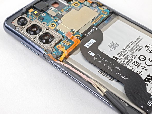
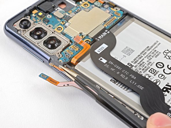
– Alrighty, tech superheroes! Let’s give those edge cables a little space on the motherboard. Carefully bend both of the right edge cables away from their cozy little spot with your trusty tweezers or fingers. If you need help, you can always schedule a repair!
Tools Used
Step 40

– Grab your trusty Phillips screwdriver and unscrew the tiny 4mm screw that’s holding together the camera bracket and the motherboard to the frame. Easy peasy!
Step 41
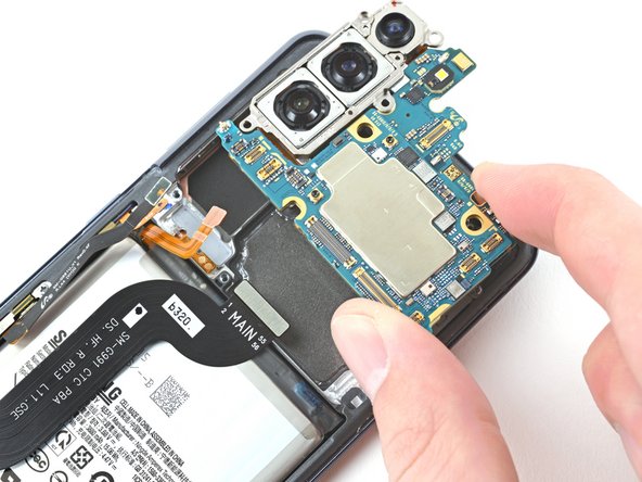
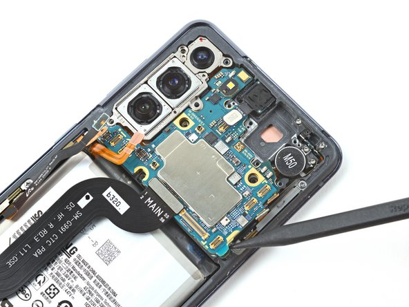

– Slide a spudger between the bottom-right edge of the motherboard and the frame—easy peasy!
– Gently pry up with the spudger to pop those clips holding the motherboard in place.
– Now, using your fingers, carefully lift out the motherboard. You’ve got this!
Tools Used

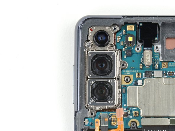
Step 43

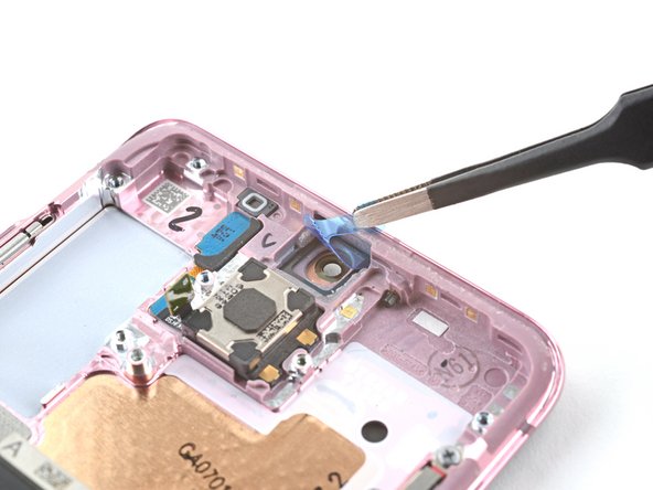
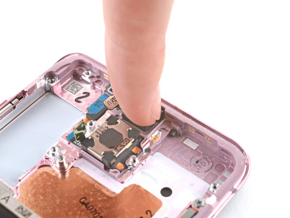
– Slide the tip of your spudger into the space between the frame and the front camera.
– Gently pop the spudger to free the front camera.
– With tweezers or your fingers, lift out the front camera.
Step 44

– As you put everything back together, keep these handy tips in mind to get your front camera reinstalled like a pro:
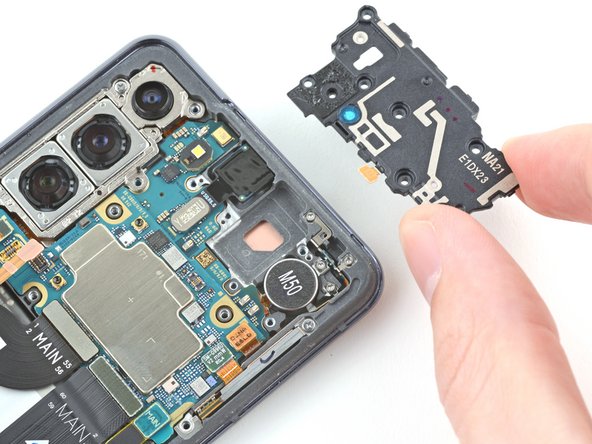
Step 45


– Grab your trusty Phillips screwdriver and unscrew those three 3.5mm-long screws holding the 5G mmWave antenna brackets to the frame. If you need help, you can always schedule a repair.


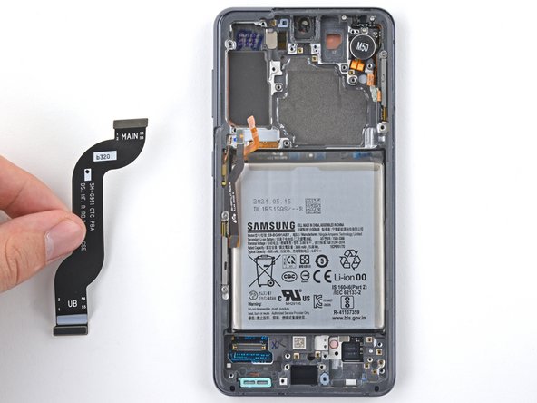
Step 50

– Now you’re down to just the screen and battery assembly!
– Size up your new replacement part against the original. You might need to move over some components or peel off adhesive backings from the new part before installing it. If you need help, you can always schedule a repair.