DIY Guide to Replace Screen on Lumia 950XL
Duration: 45 min.
Steps: 23 Steps
Hey there, tech savvy friend! In this exciting step-by-step guide from Salvation Repair, we’ll walk you through the process of swapping out the cracked or unresponsive screen on your Lumia 950XL. If you’re experiencing a black LCD or a flickering display, this repair is for you! So let’s get started, and don’t worry if things don’t go perfectly the first time – it’s all part of the learning journey. If you need a hand, don’t hesitate to schedule a repair with us.
Step 1
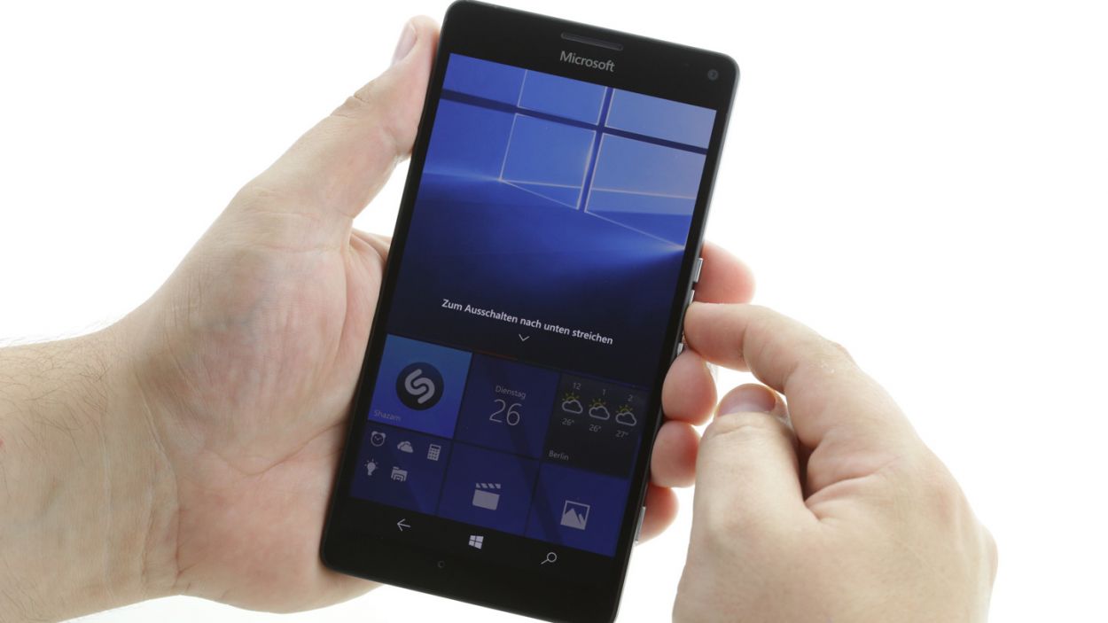
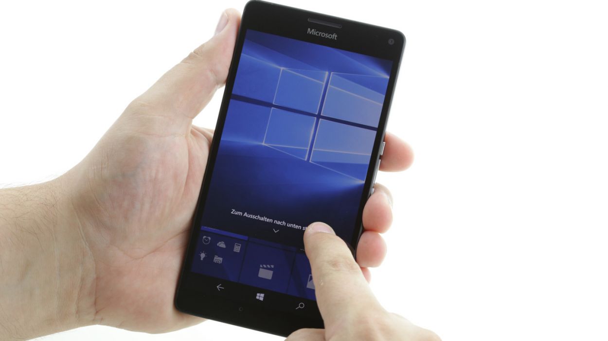
– First things first, let’s power down your device! Just press and hold that power button until you see the message that says, ‘slide down to power off.’
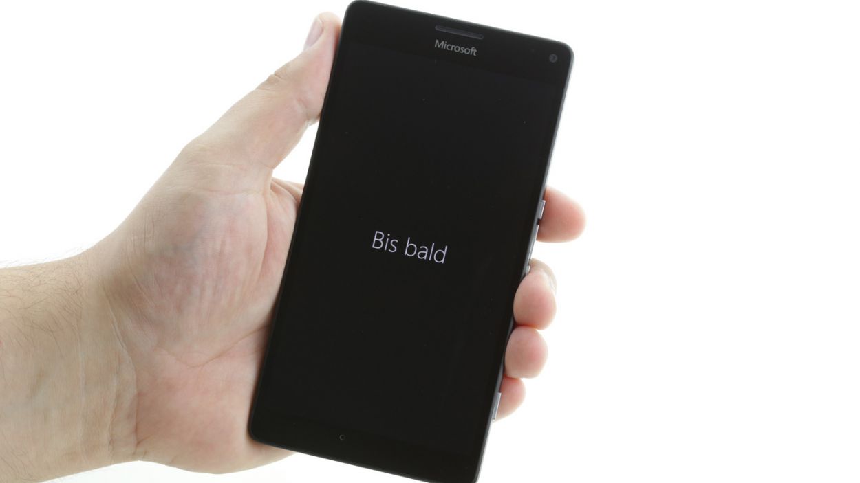
– Now, give your screen a gentle slide down with your finger until you see ‘goodbye’ pop up, and voilà! Your device is now off and ready for some TLC.
Step 2
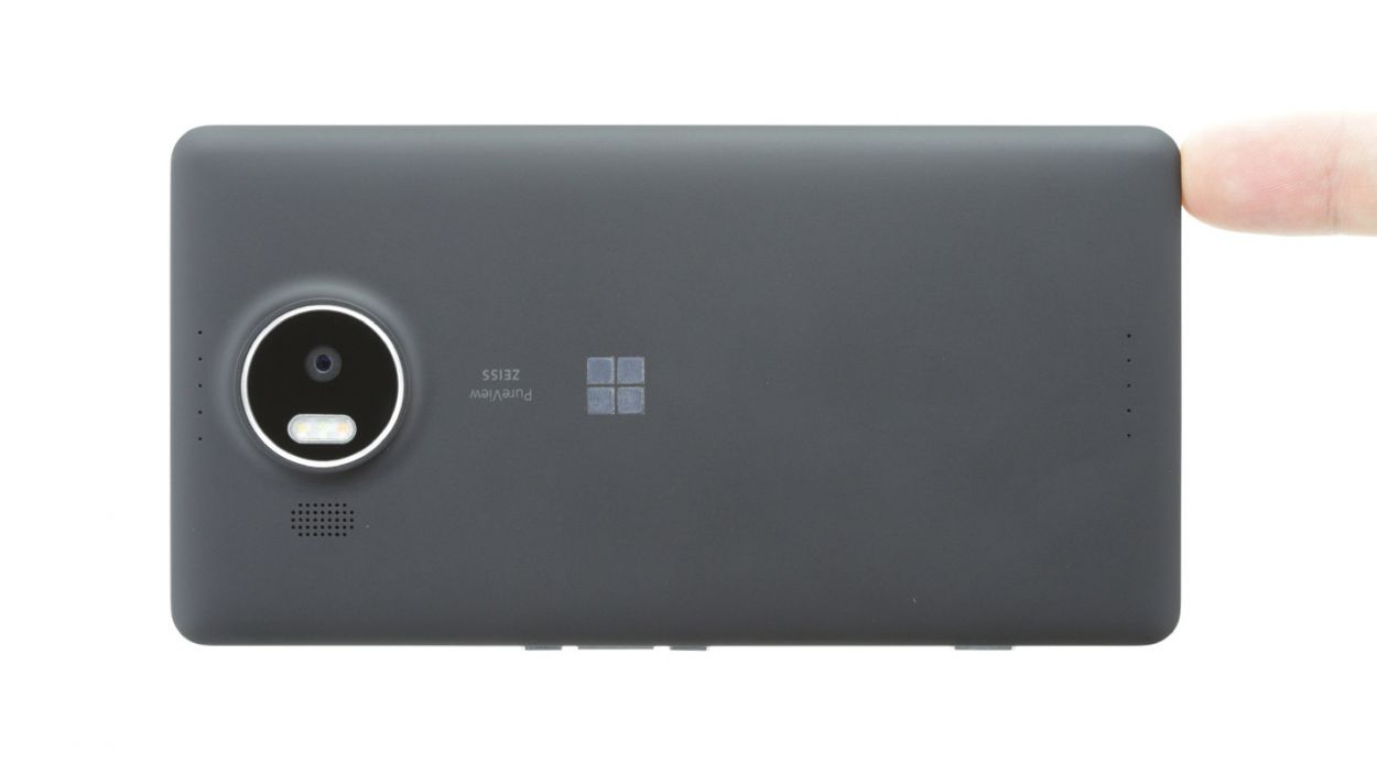

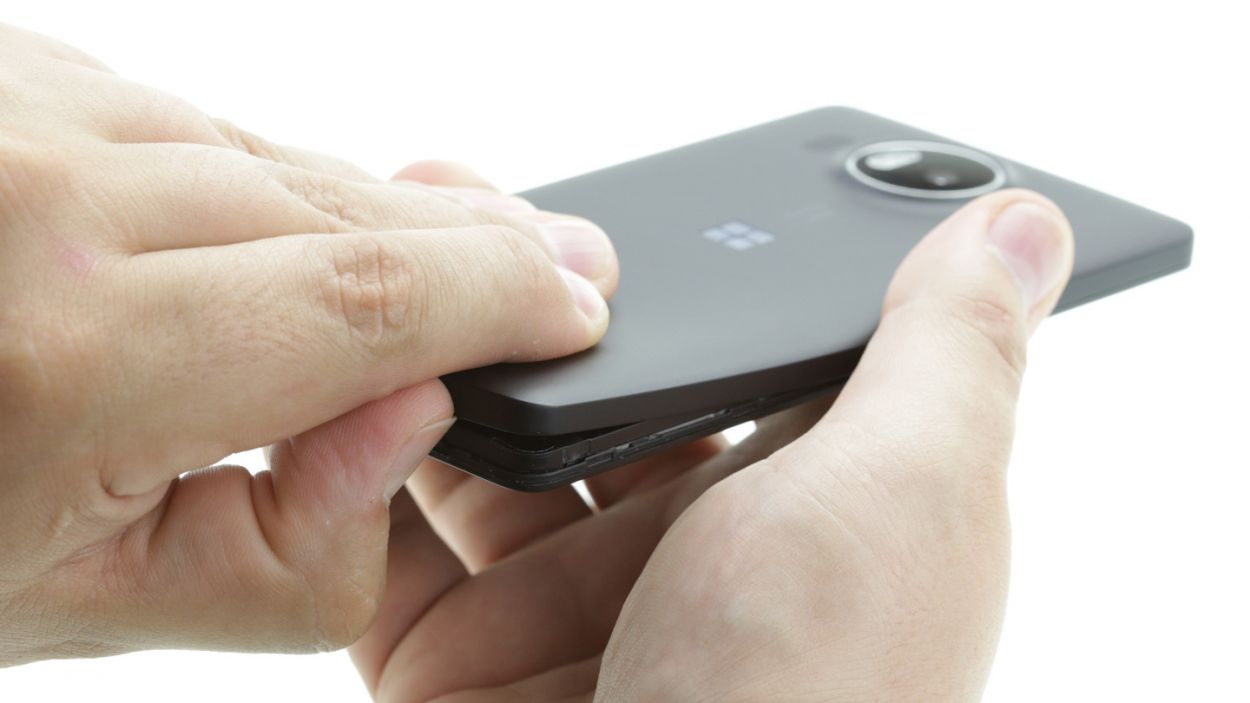
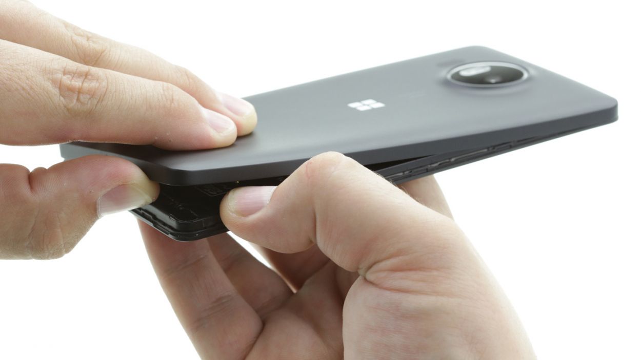

– Gently pry off the back cover from the enclosure frame. There’s a nifty little slot at the bottom just waiting for your fingernail or a trusty tool.
– Slowly detach the back cover from your device, taking your time.
– Carefully remove the back cover from your device and set it aside.
Step 4
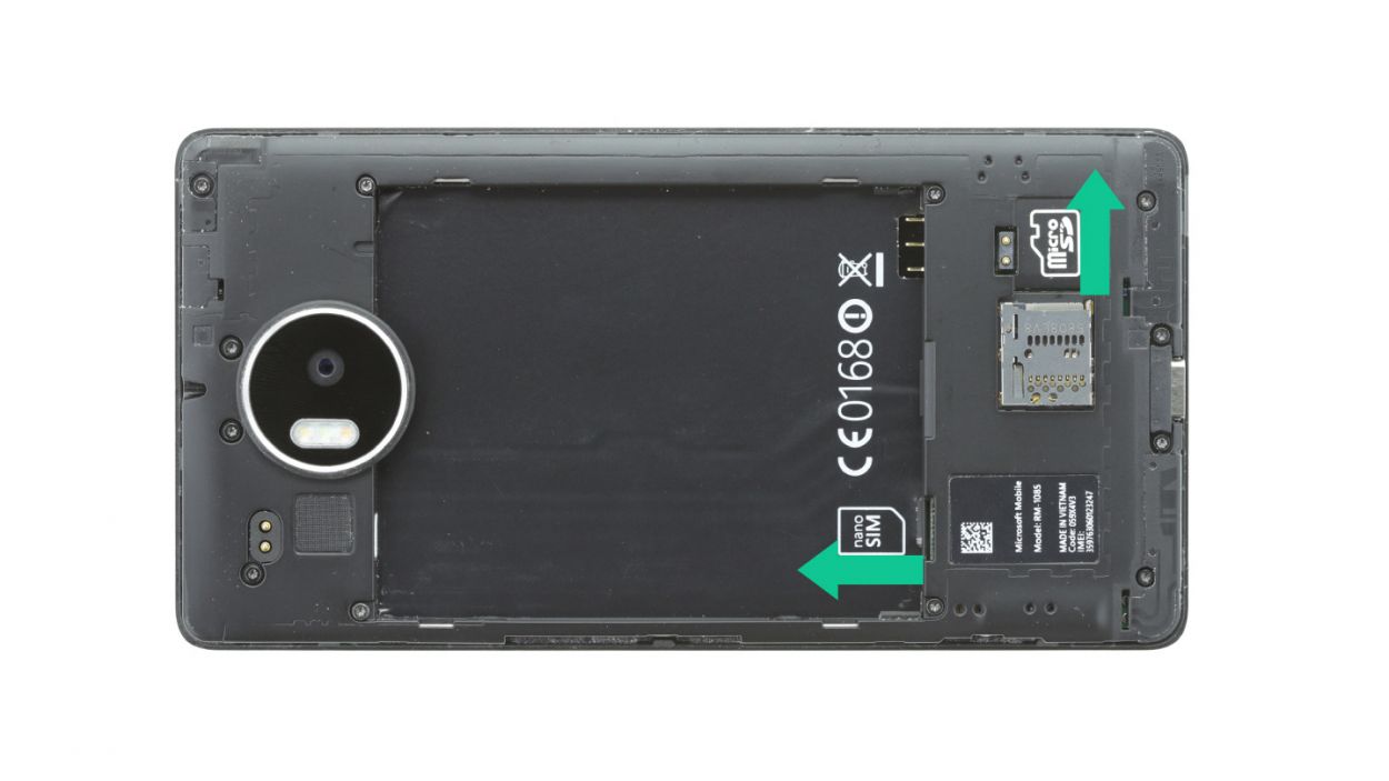
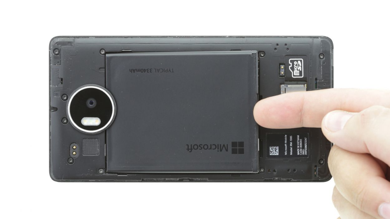
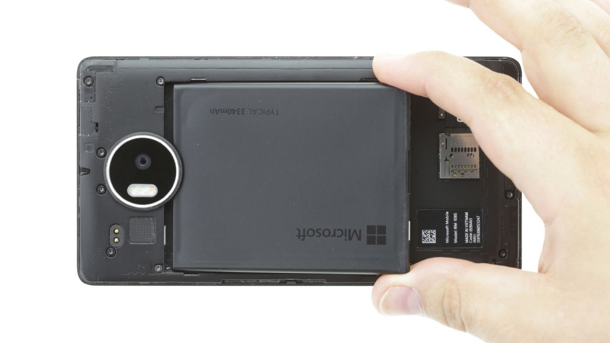
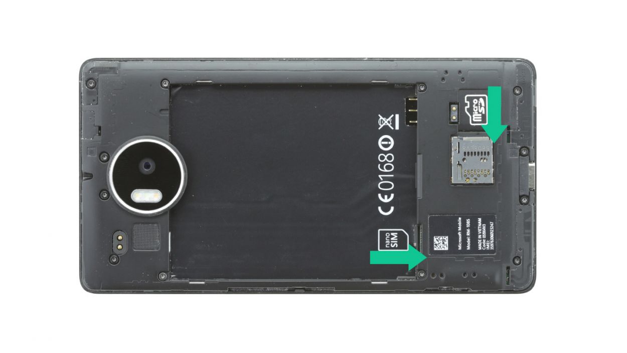
– Pop out the SIM and microSD cards from your device like a pro!
Step 5
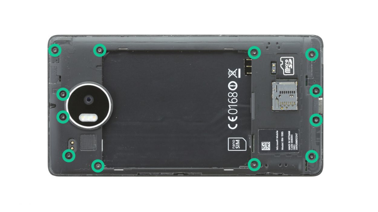

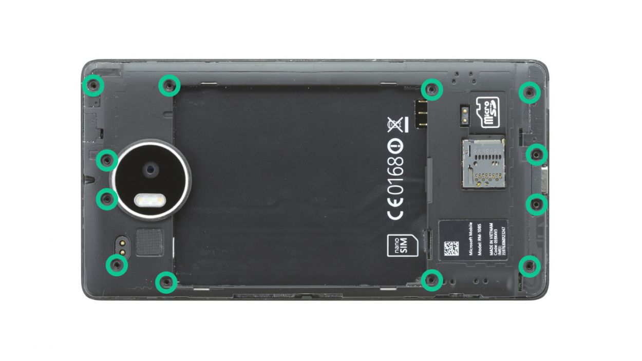
– First things first, let’s tackle those twelve screws holding the chassis to the enclosure. Grab your trusty 4.5 mm T4 Torx screwdriver and get to work!
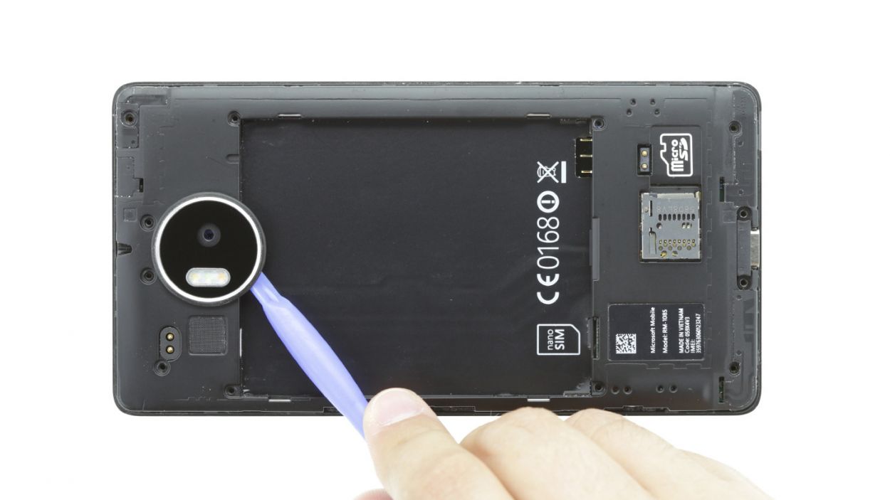
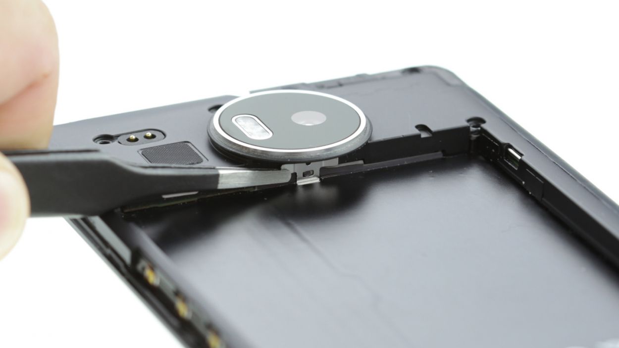
– Next up, the chassis is snugly hooked onto the enclosure right below the rear camera. Use your tweezers or spudger to gently unhook it—easy does it!
– Now, lift that chassis up and away. You’ve got this!
Step 6

– Gently detach the headphone jack’s connection from the motherboard, like you’re giving it a little hug goodbye.
– Next, pop that jack out of the enclosure with care, as if you’re unveiling a surprise!
Step 7
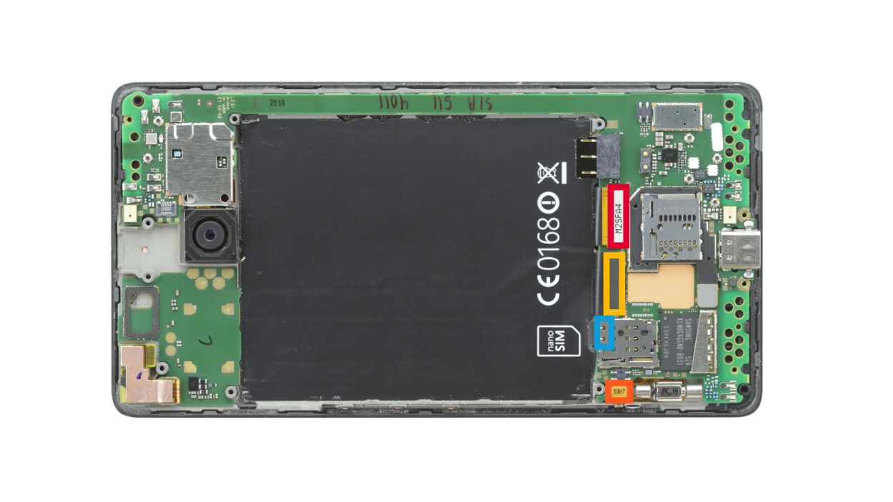
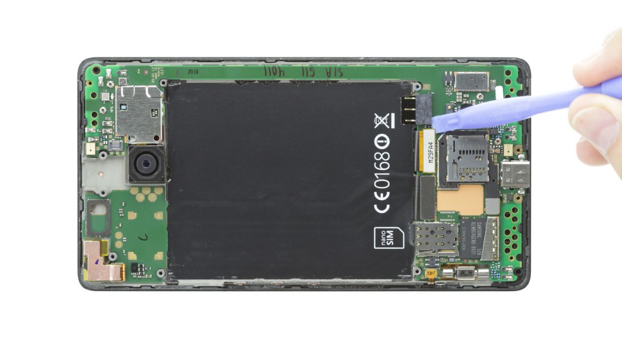
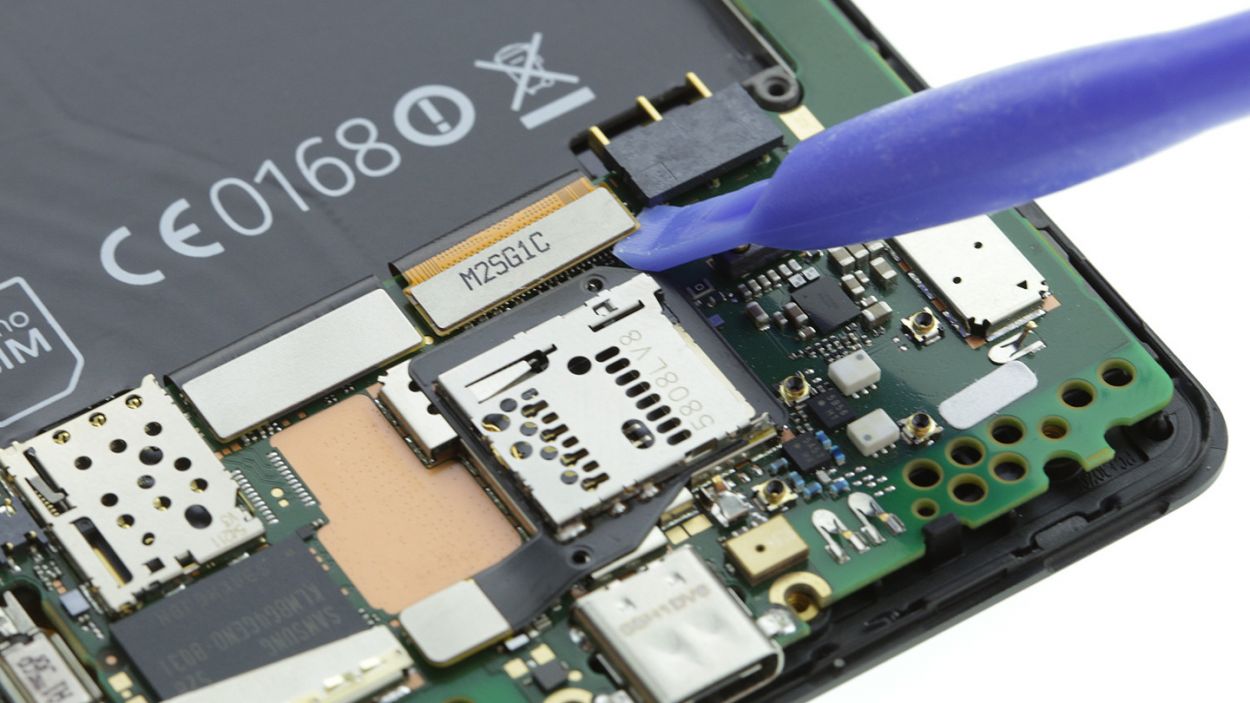

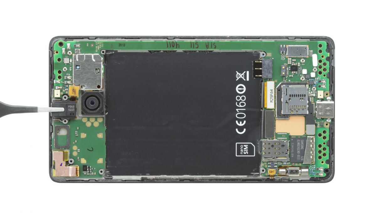
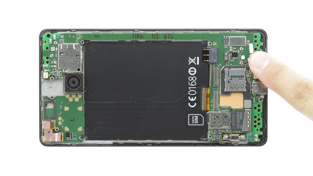
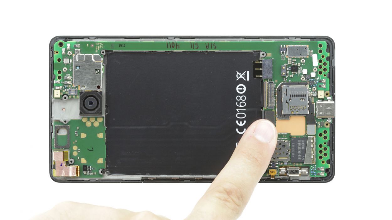
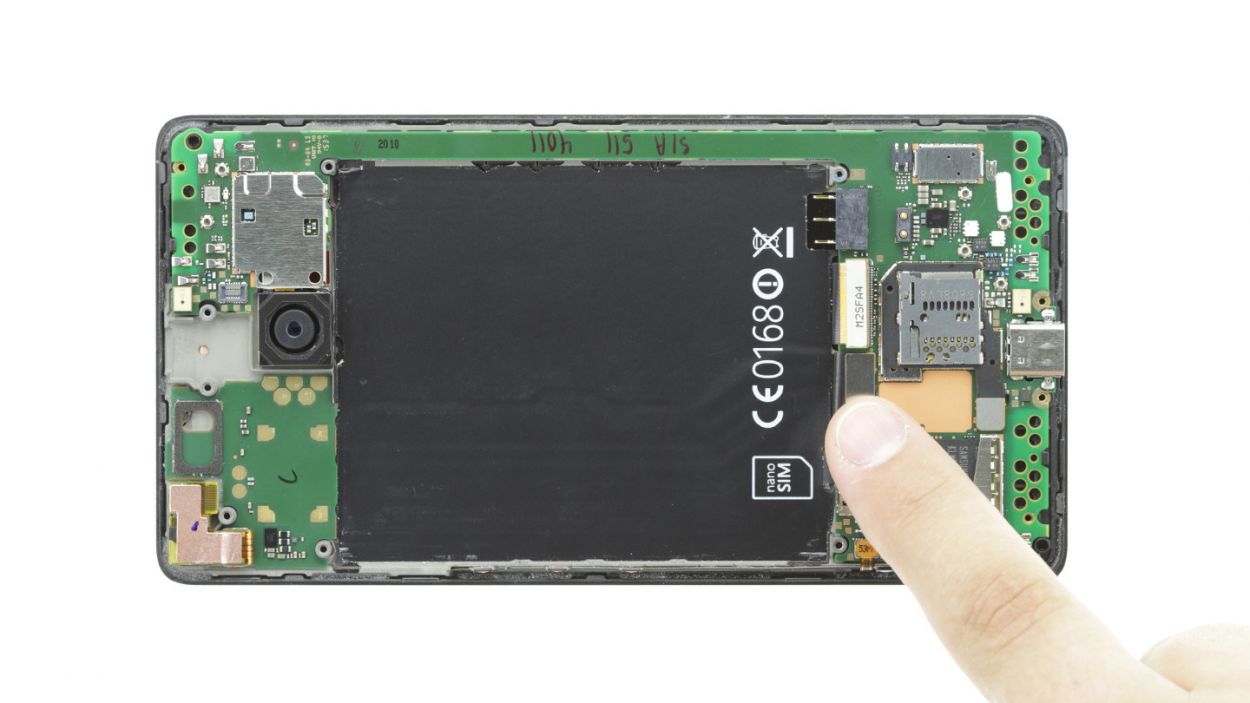
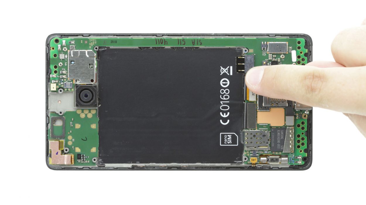
– Time to get familiar with the brave new world of electronics! Using the provided spudger, carefully disconnect those four plug contacts from the motherboard. Think of it like unsnarling a few pesky knots!
– So, what’s first? Yep, it’s the display contact! You got this!
– Let’s move on to the front camera connection – it’s a piece of cake!
– Time to disconnect those control buttons! Easy breezy!
– Now we come to the proximity sensor on the back – it’s all about patience. If it gets a bit tricky, no worries, remove the board from the enclosure and try again (see the next step).
Step 8
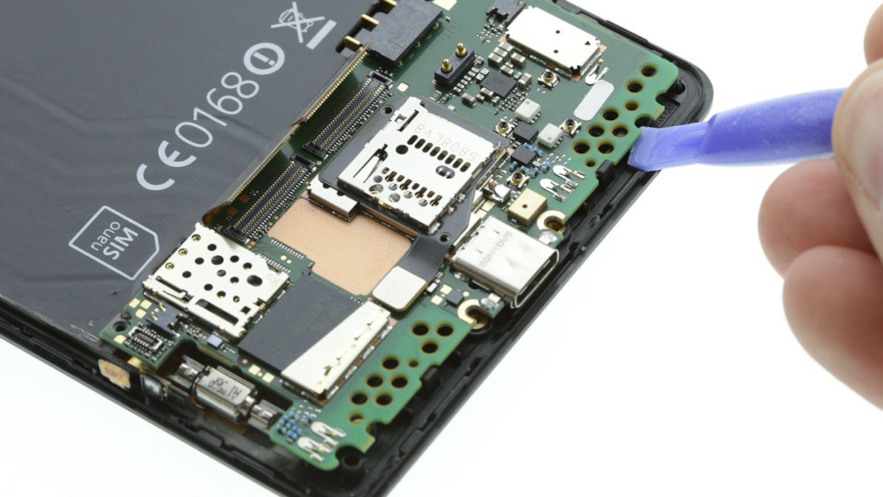
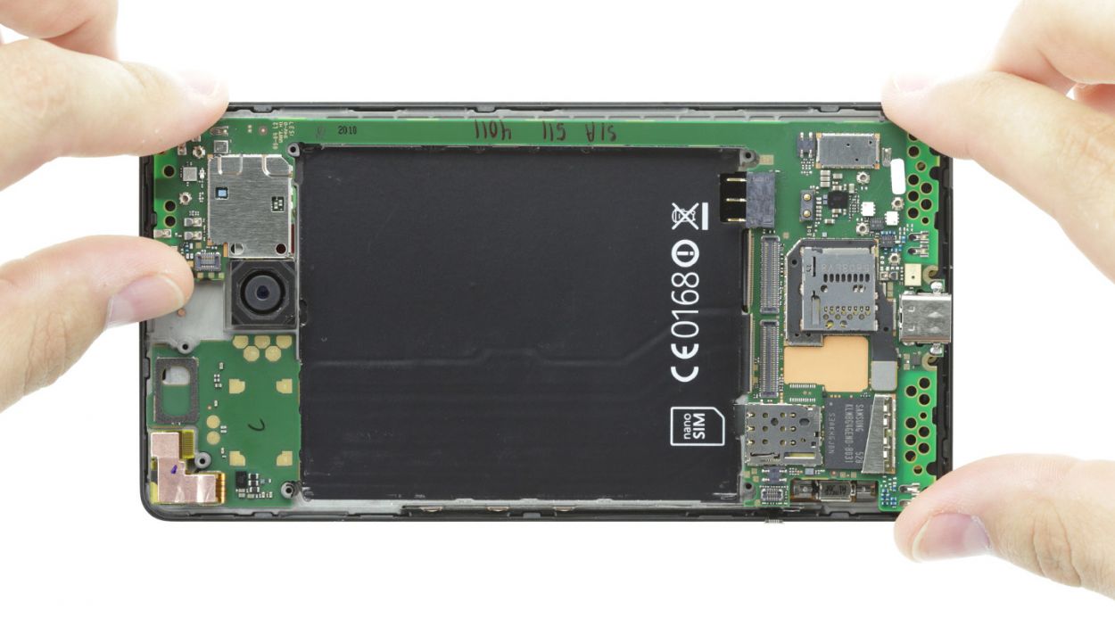
– Give the board a friendly nudge, slideshow style! Insert your spudger beneath it and gently lift, releasing it from its attachment points. Be careful not to dislodge any precious components though.
– With a cheerful ta-da, the entire board is now detached! Go ahead and carefully lift it out for further exciting repair adventures. If you need help, you can always schedule a repair at Salvation Repair.
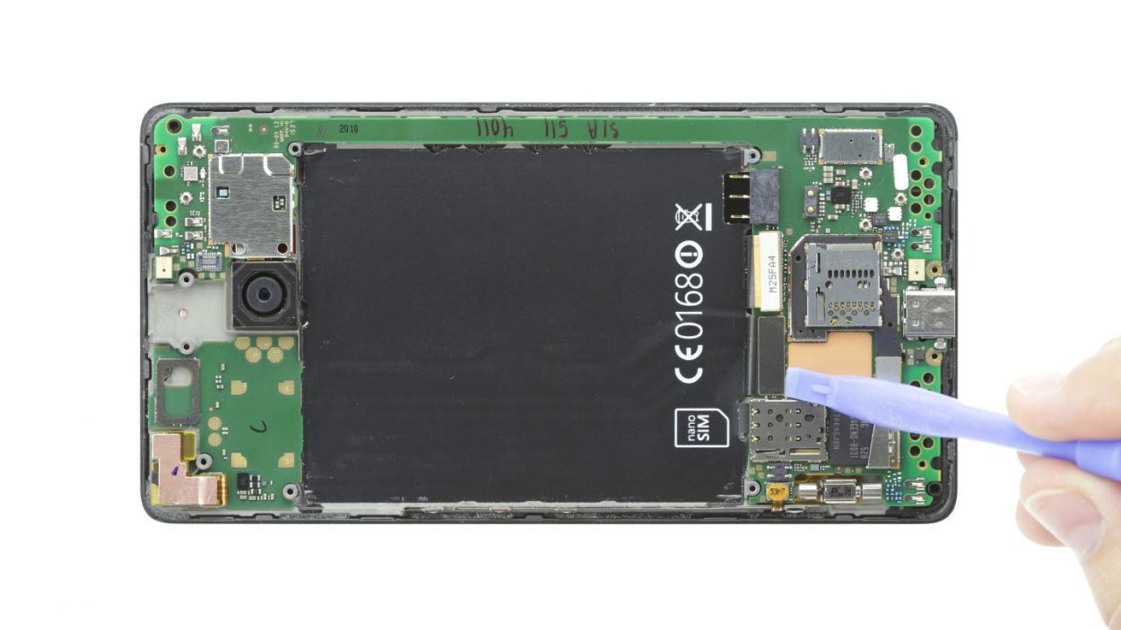
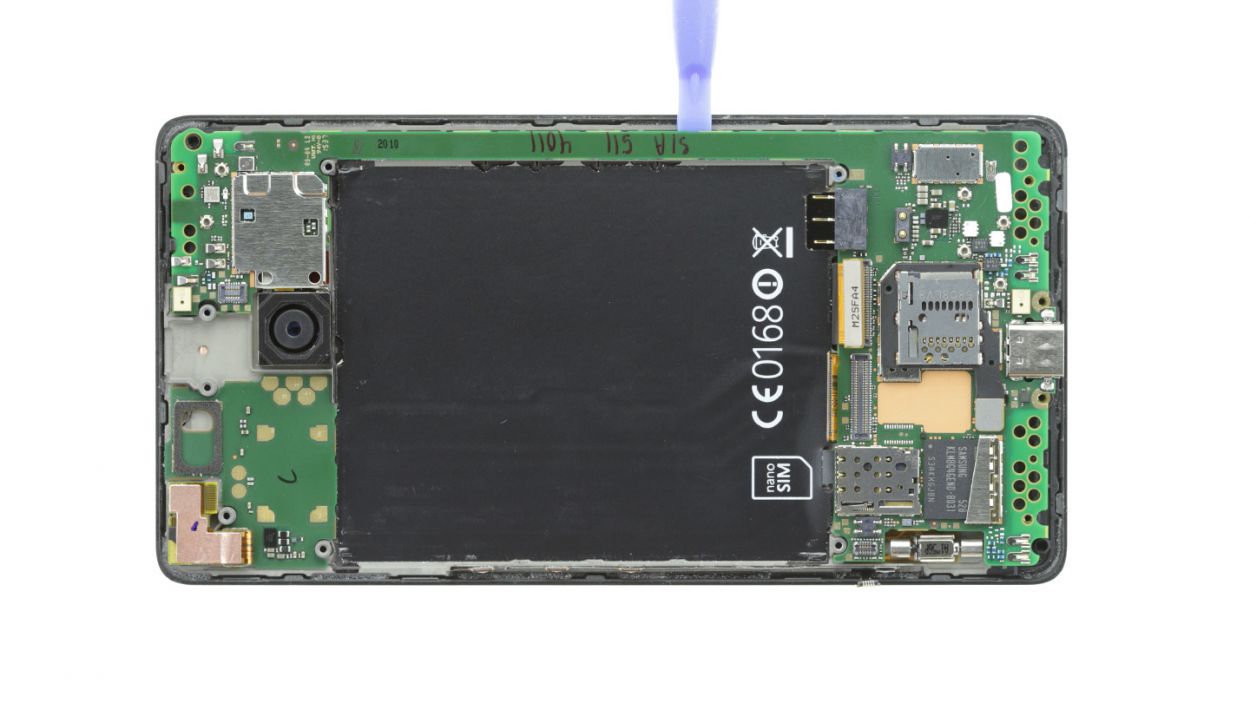
Step 9
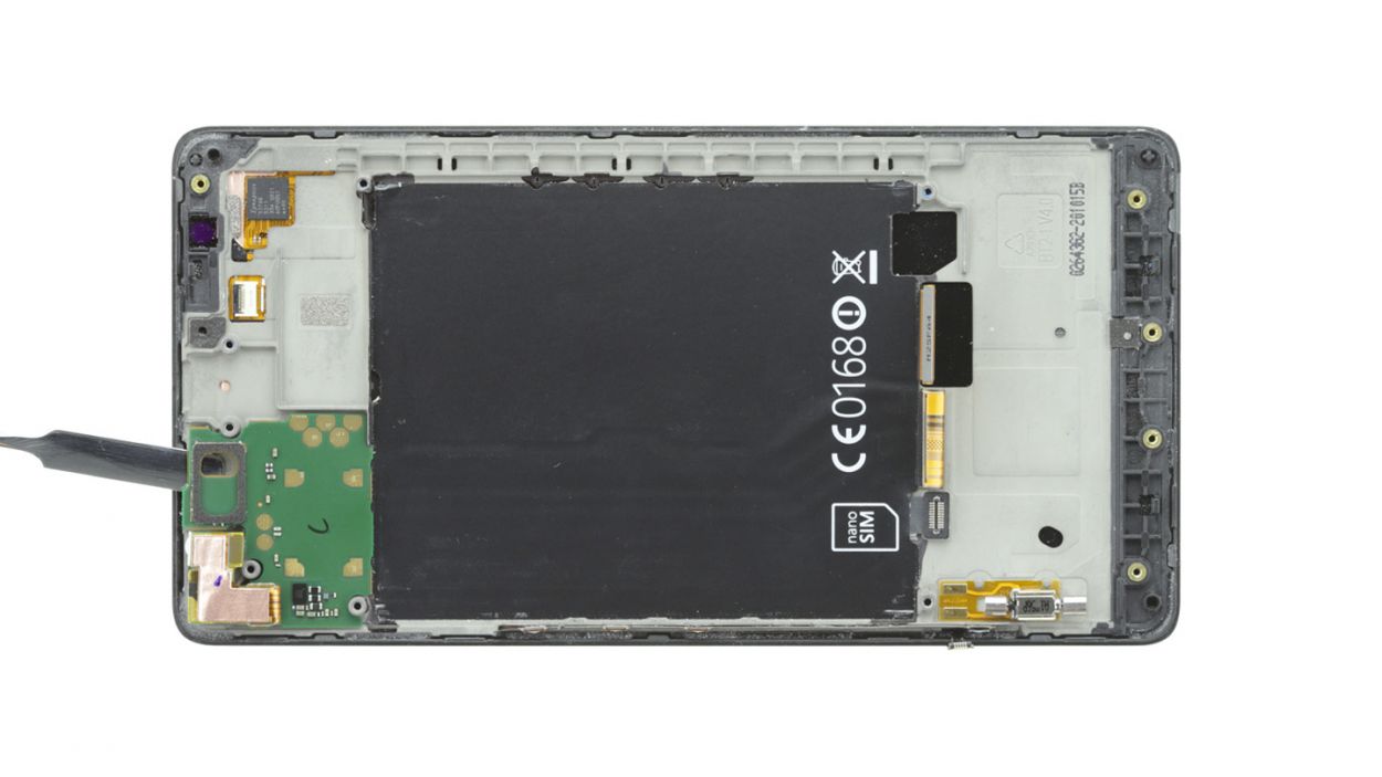
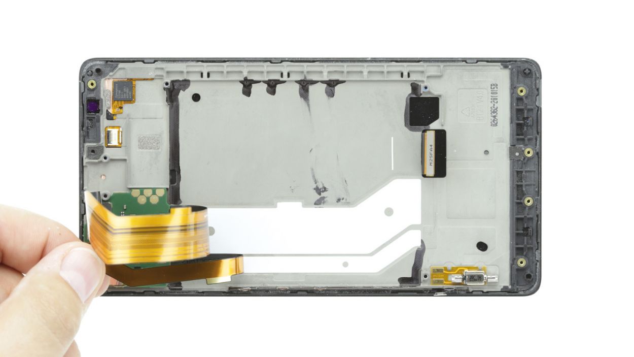
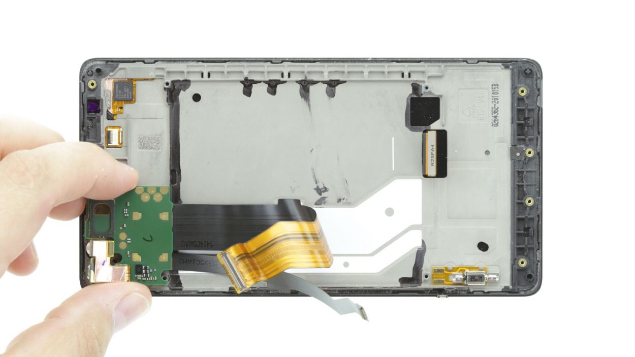
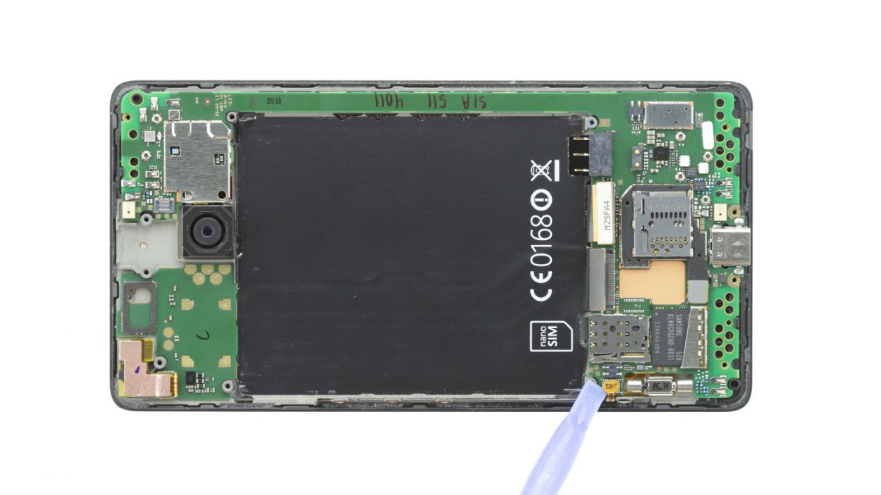
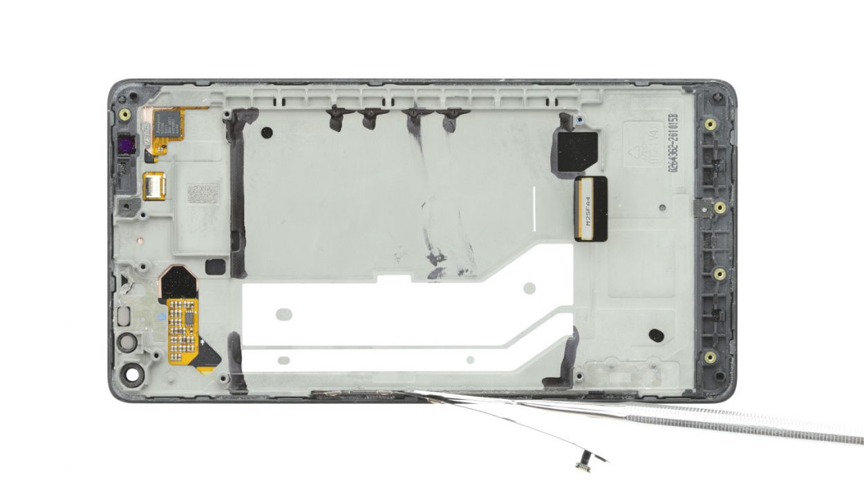
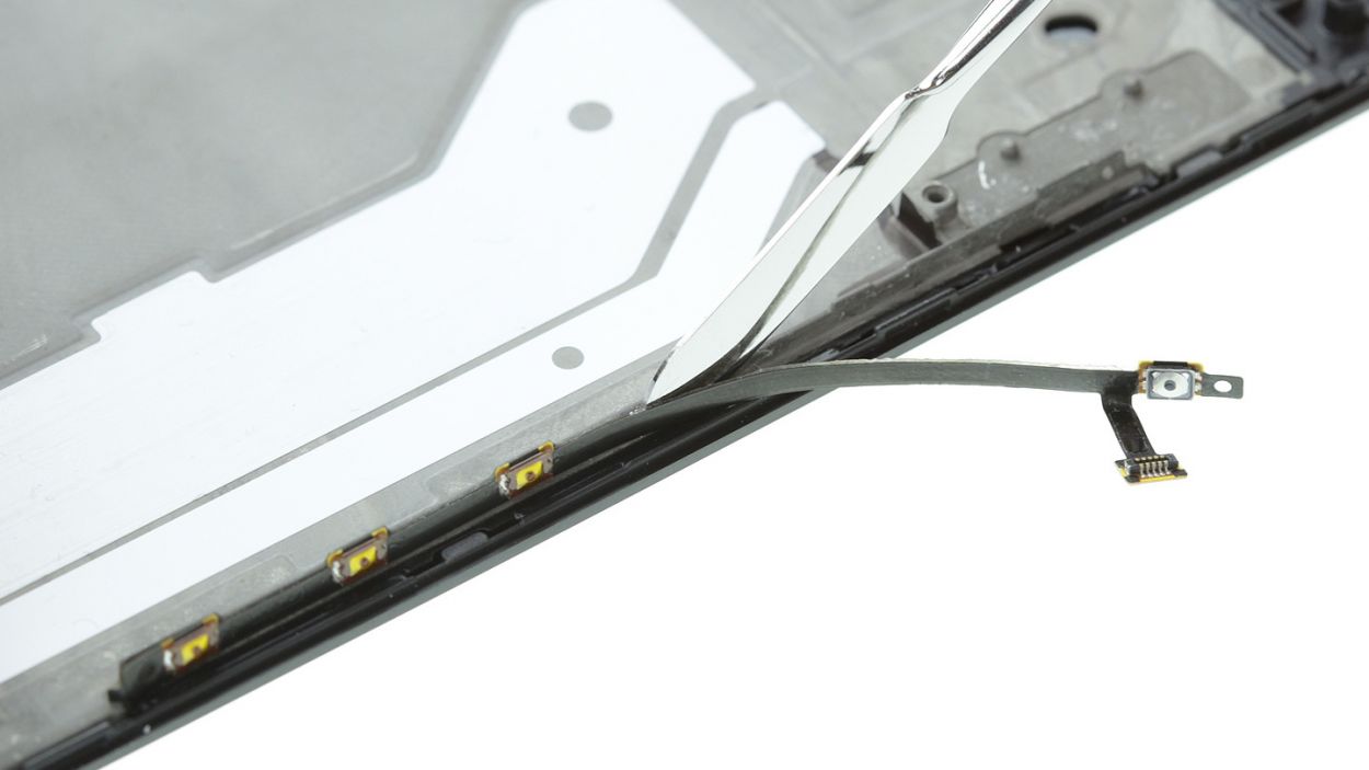
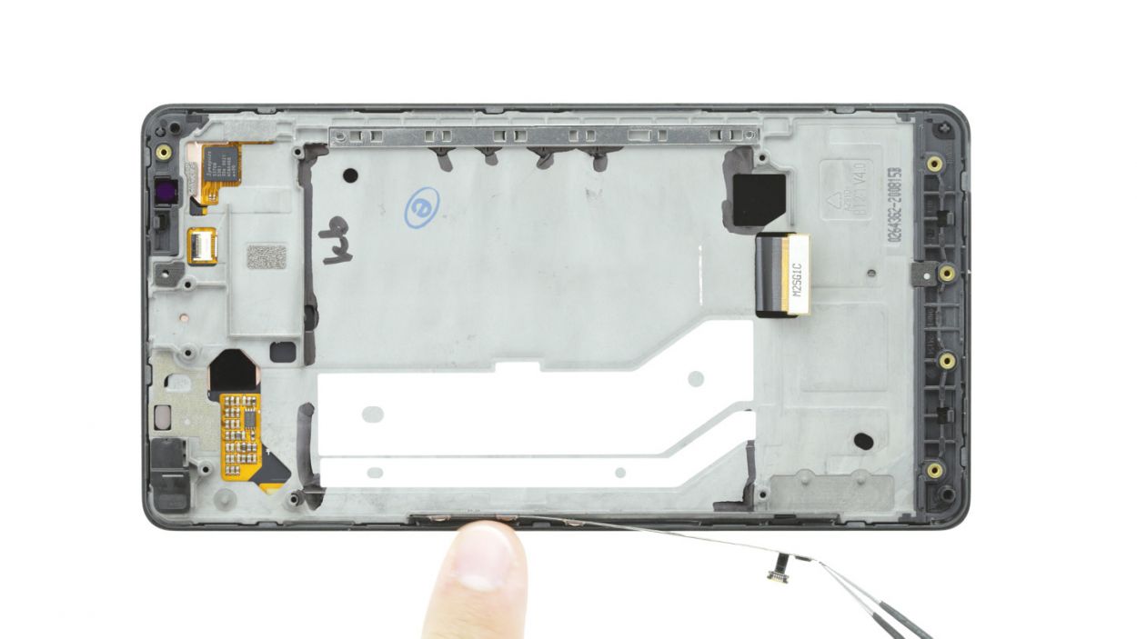
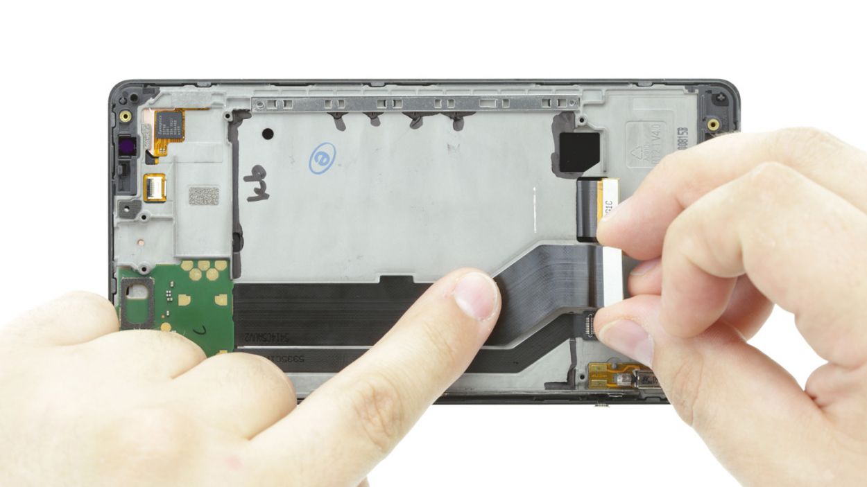
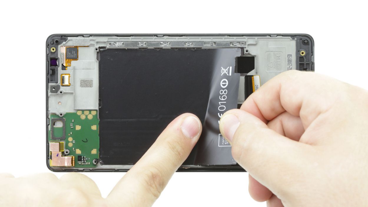
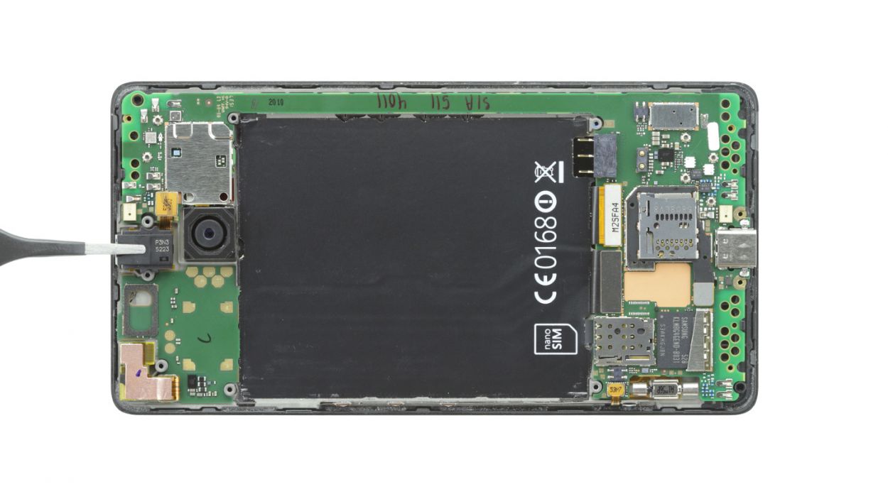
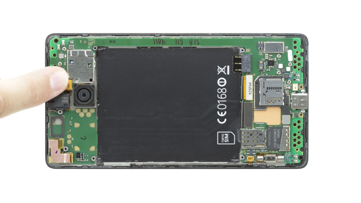
– Gently wiggle out the PCB with the front camera and other sensors from the enclosure. Just slide that steel spatula between the PCB and the enclosure to break the glue’s grip. Watch out for those components on the back of the PCB—they’re a bit shy!
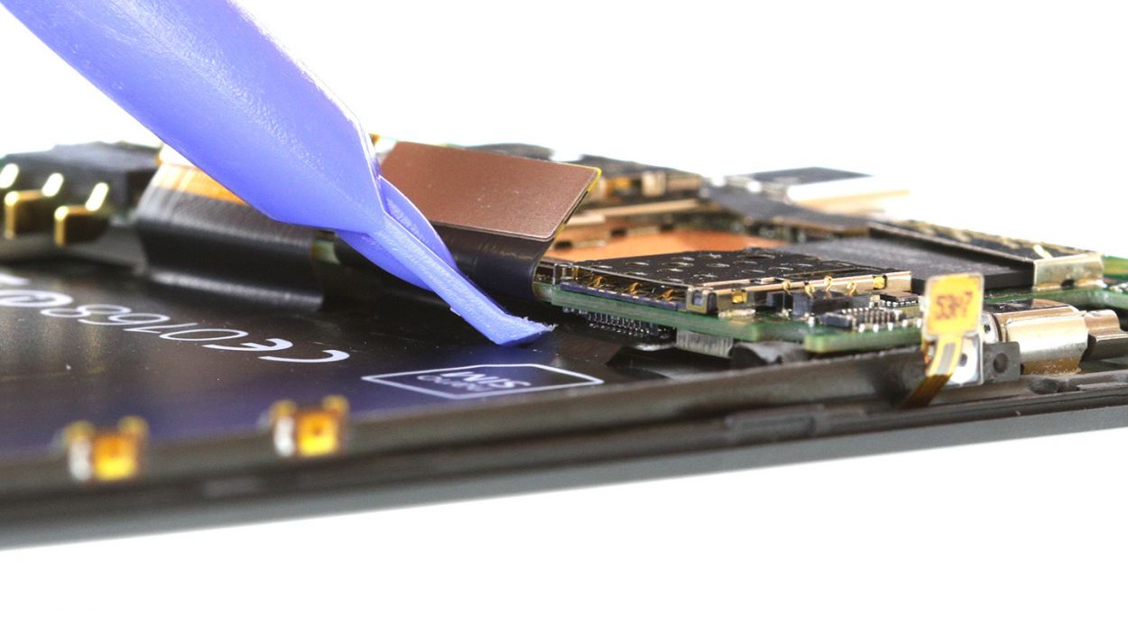
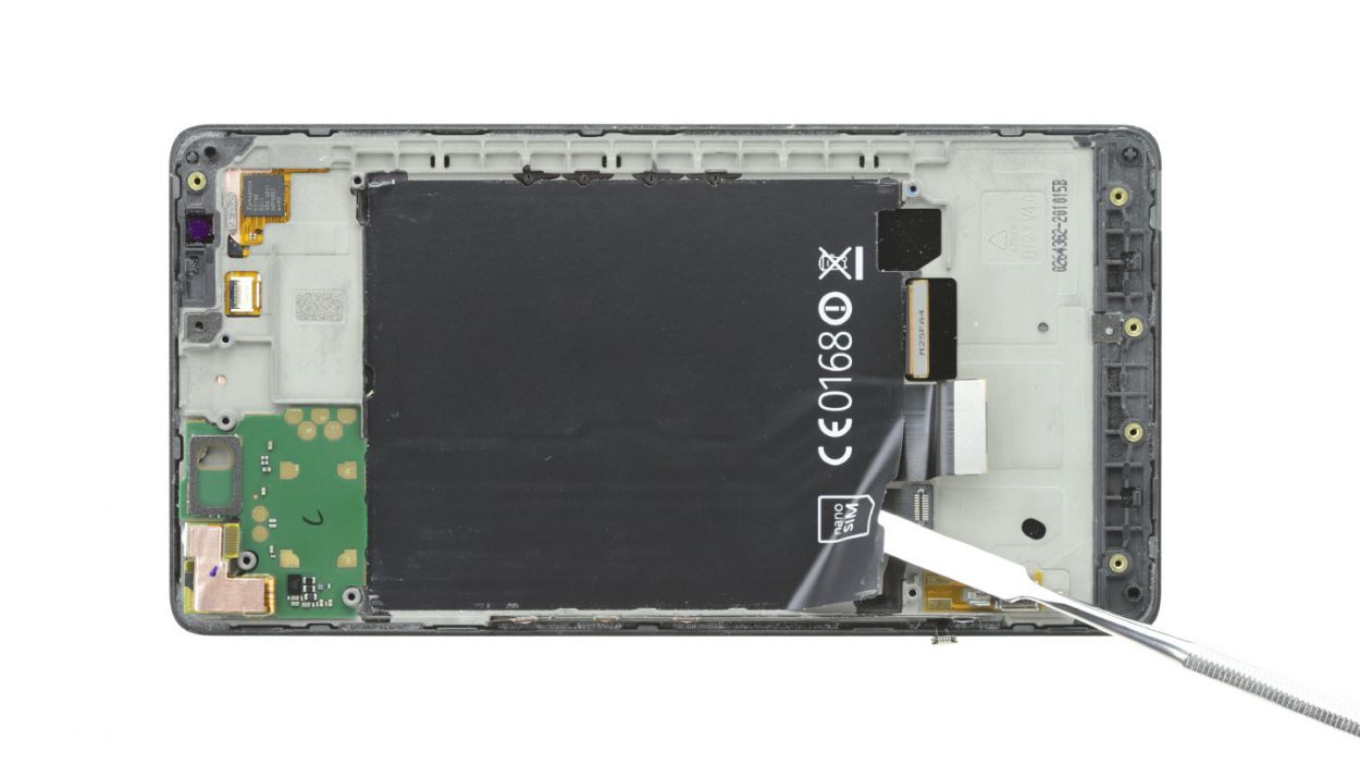
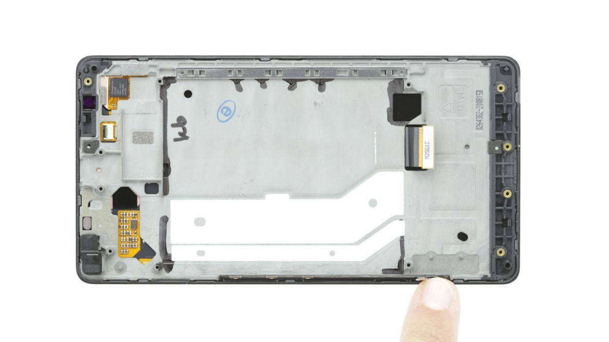
– Next up, let’s get rid of that black protective film covering the ribbon cables. Carefully slide the spatula underneath the film and peel it away like a pro.
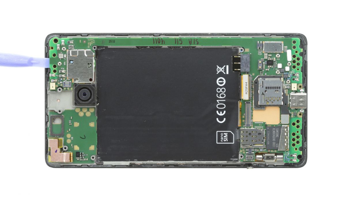
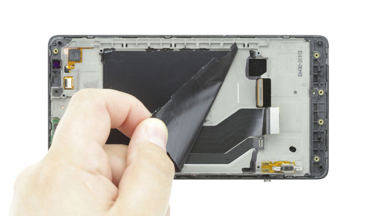
– Time to say goodbye to all that film—peel it off completely!
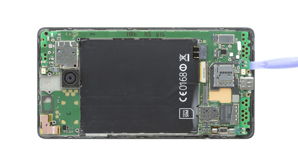
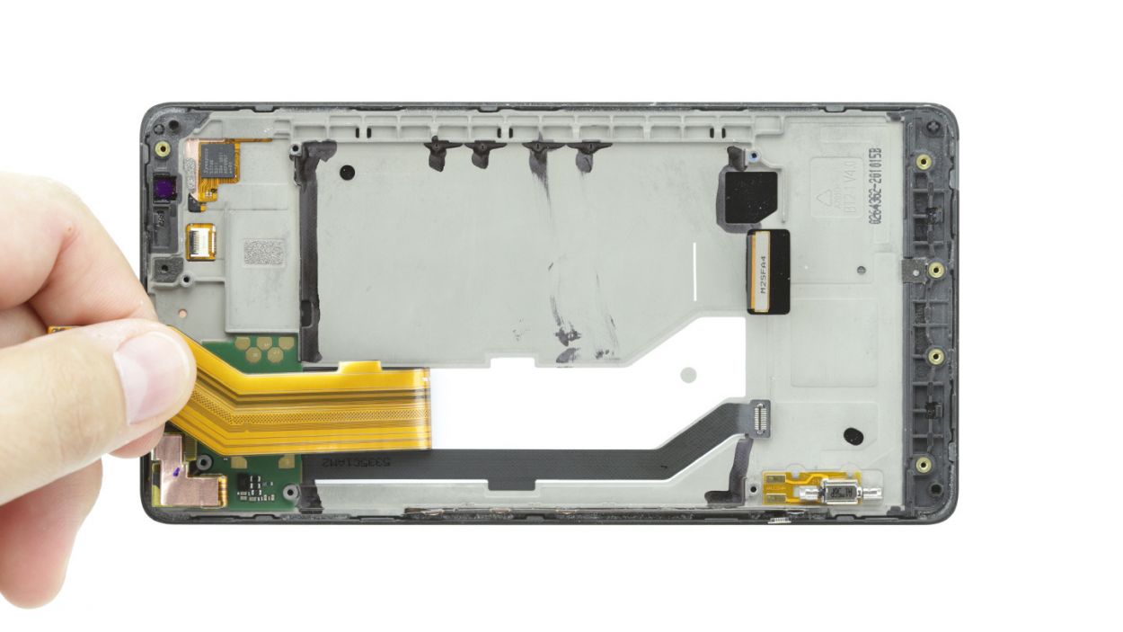
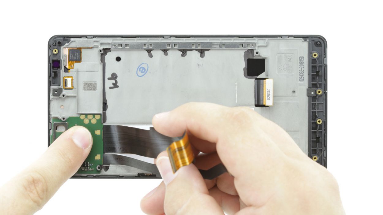
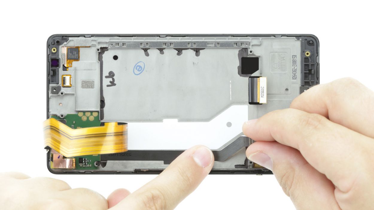
– Now, with a gentle touch, detach the two ribbon cables from the frame. Remember, no need to muscle through this part!
– Finally, it’s time to remove the board. You’ve got this!
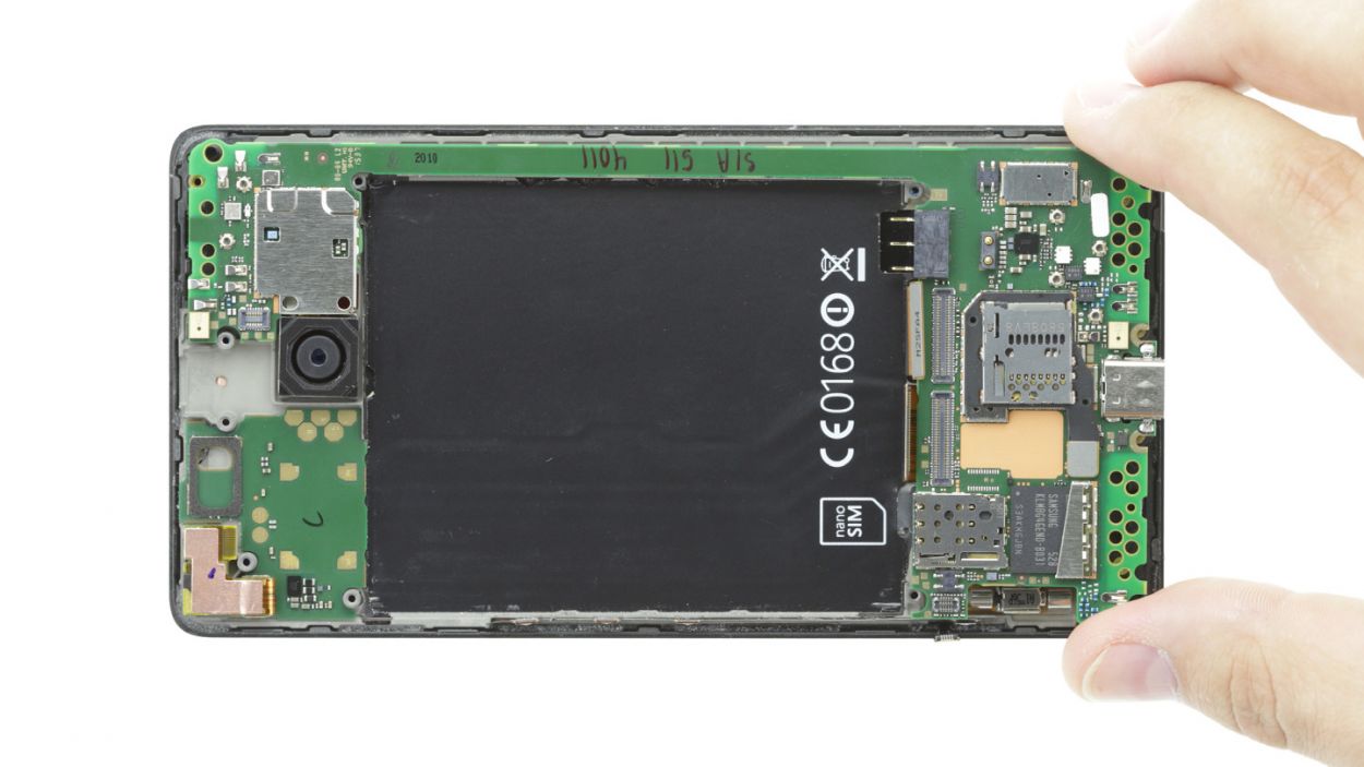
Step 10
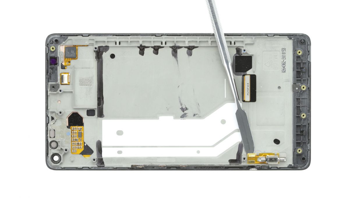
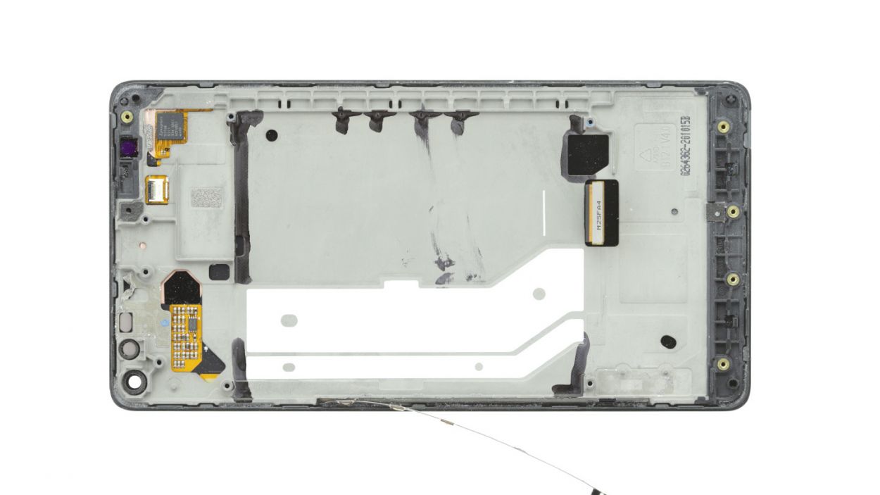
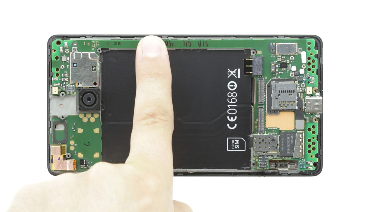
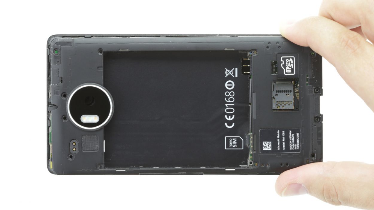
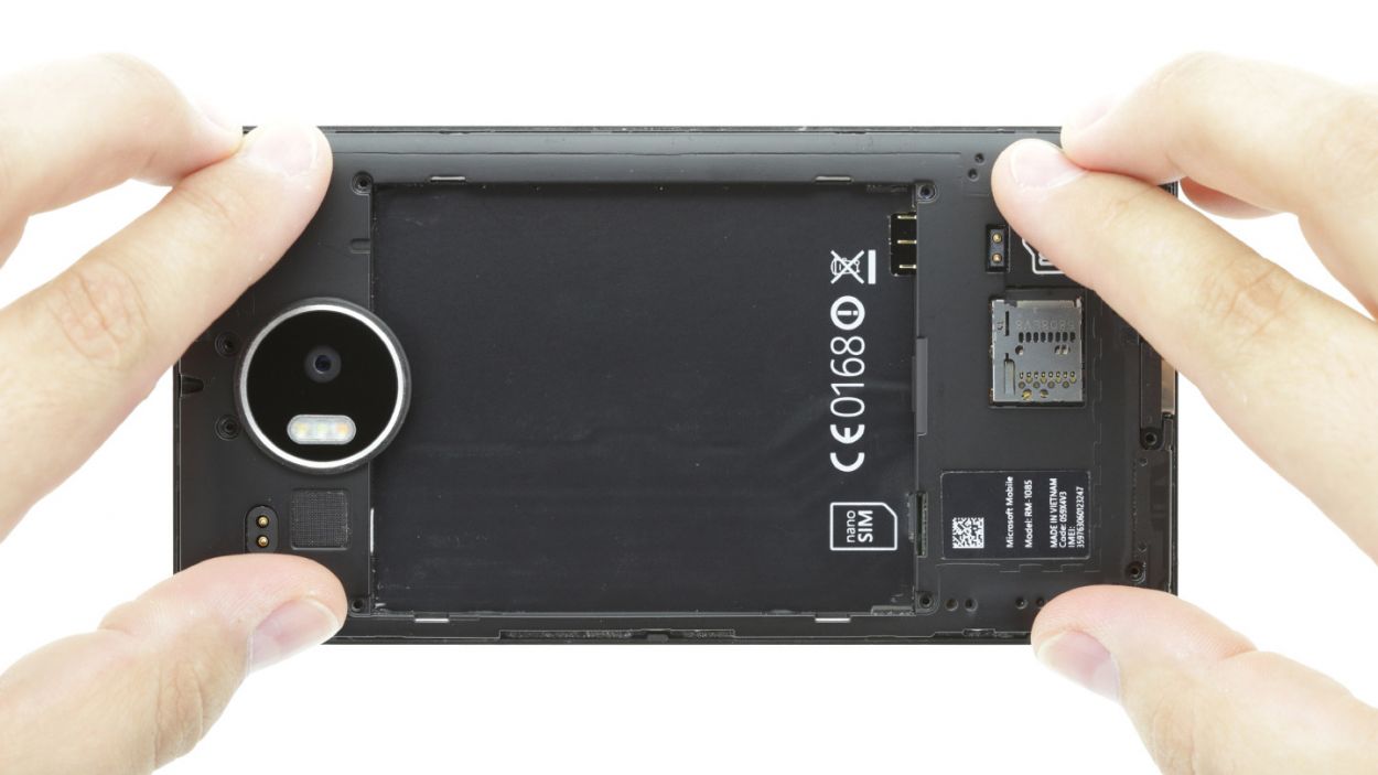
– The vibrator motor is stuck to the enclosure with some glue. Gently slide a steel spatula between the motor and the enclosure to break that bond. Just be careful not to damage the motor’s yellow backing material.
– Now, go ahead and remove the motor.
Step 11
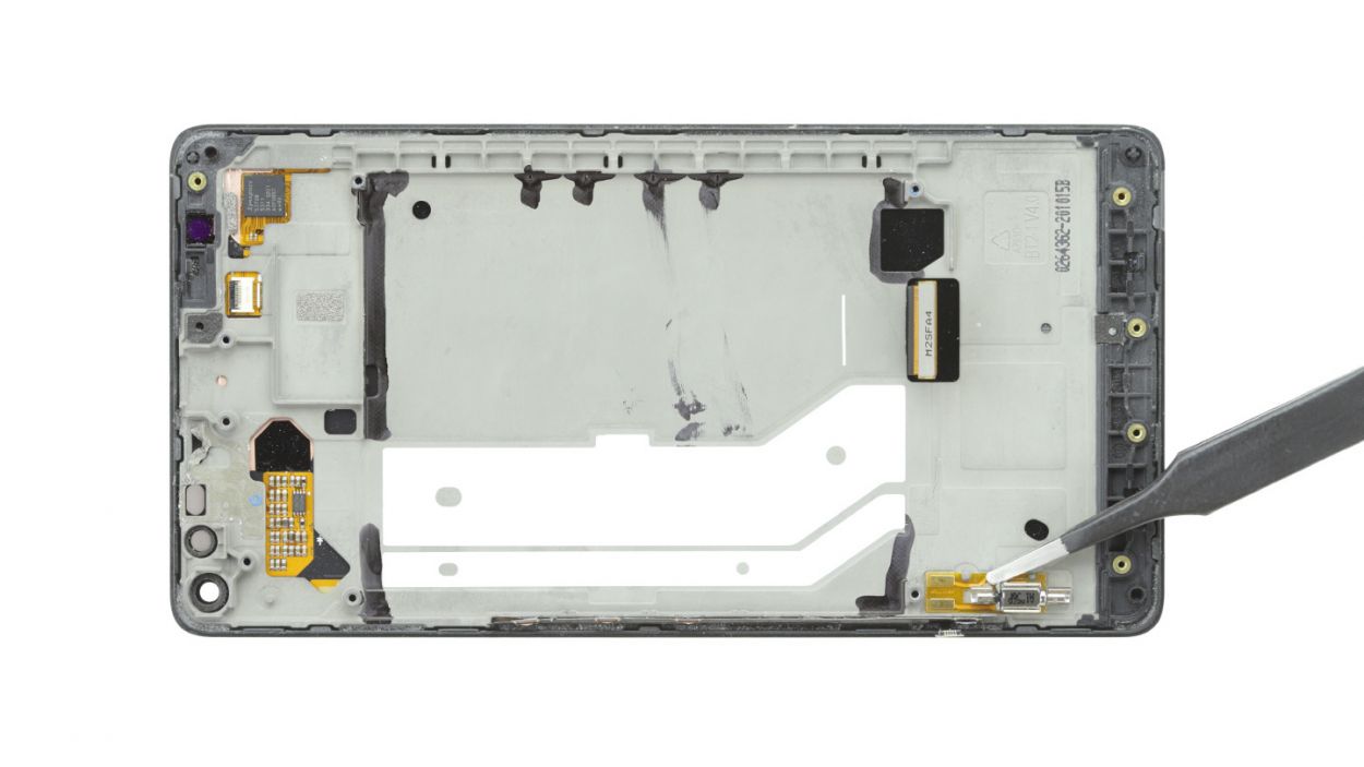
– Let’s get those control buttons off! Grab your trusty steel spatula and gently slide it between the buttons and the frame. These little guys are glued in there, so take your time until they pop right off.
– Once they’ve loosened up, go ahead and remove the buttons.
Step 13
– Time to get those control buttons back in place! Make sure they’re cozy and correctly positioned. Look for the tiny holes on each end that need to align with their partners in the frame. Those round openings are ready for a perfect match!
– With a little love from your finger, press those buttons onto the frame to make sure the glue really bonds. You’ve got this!
Step 14


– Alright, let’s get this fix done! Carefully place the vibrator motor back in its cozy little home, making sure it’s snapped into place. Line up those tiny tabs with the enclosure, and you’re golden!
– Next up, press down gently on the motor to secure it. Easy peasy!
Step 15
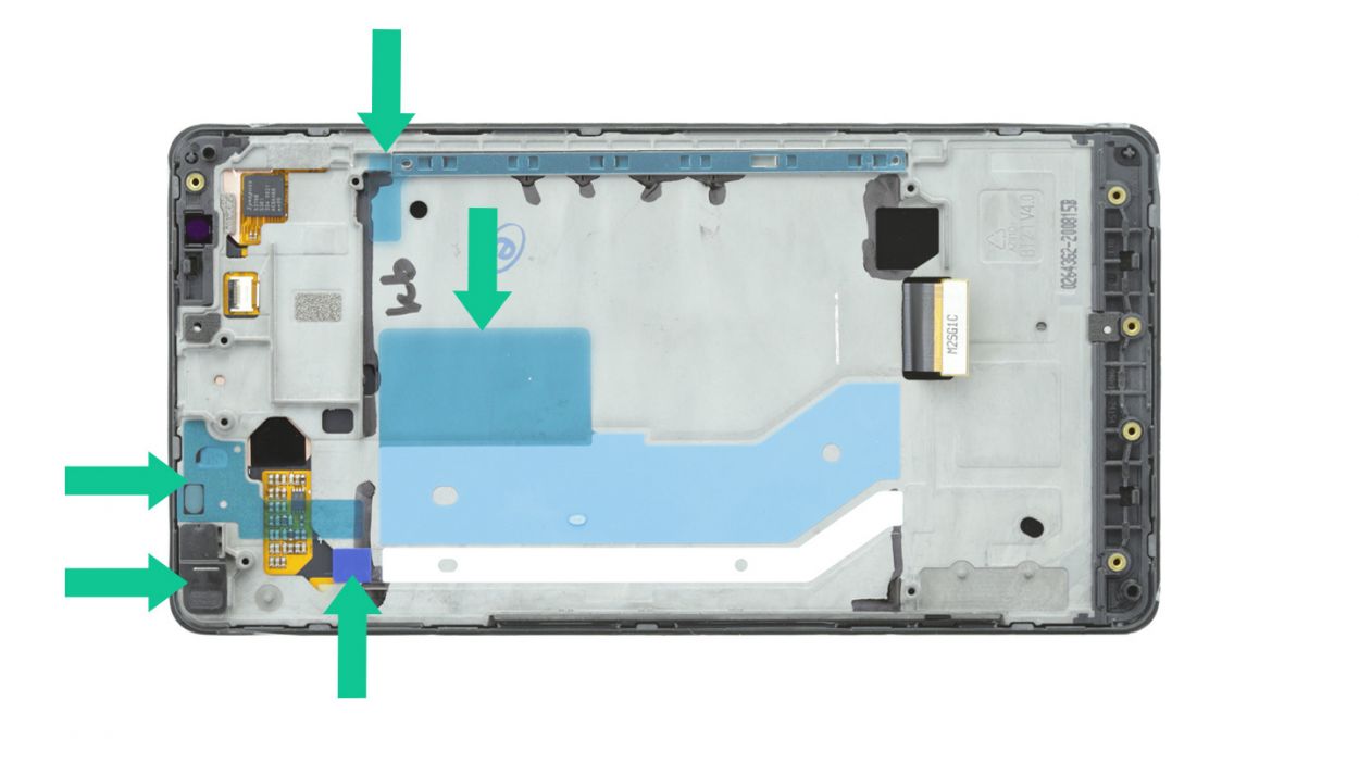
– First up, slide that PCB into the upper edge of the enclosure. Give it a gentle press with your finger to make sure it sticks like a champ!
– Next, let’s route those two ribbon cables inside the enclosure. The adhesive+strips+Lumia+950XL&crid=1TJIMMAJSUJUZ&sprefix=repair+tools%2Caps%2C165&linkCode=ll2&tag=salvationrepa-20&linkId=c486487cf454ce8edd6f5beefab4110f&language=en_US&ref_=as_li_ss_tl’>adhesive strips are your best buddies here, guiding you on exactly where to place the cables. Stick them down nice and flat right over those white adhesive+strips+Lumia+950XL&crid=1TJIMMAJSUJUZ&sprefix=repair+tools%2Caps%2C165&linkCode=ll2&tag=salvationrepa-20&linkId=c486487cf454ce8edd6f5beefab4110f&language=en_US&ref_=as_li_ss_tl’>adhesive strips.
– Finally, cover those ribbon cables with the sleek black film to keep everything tidy!
Step 16

– Gently slide the board back into its cozy home in the enclosure.
– Give it a little press until you hear that satisfying click, letting you know it’s snug and secure!
Step 17


– Carefully connect the following four plug contacts to the motherboard. You’ll hear the contacts click into place. Use your finger to carefully press all of them into the appropriate sockets. Start with the proximity sensor. If the proximity sensor’s contact isn’t positioned right, remove the board from the enclosure and try connecting it again.DisplayFront cameraProximity sensor (back)Control buttons
Step 18
– Gently slide the jack back into its cozy spot at the top of the enclosure.
– Next, make sure to connect the jack’s contact to the motherboard with care. You should hear a satisfying click when it locks into place!
Step 19
– Snap the chassis back on – it’ll click into place under the camera. Piece of cake!
– Now, grab those twelve 4.5 mm T4 Torx screws and snug them in. You got this!
Step 20
– Slide that SIM card back into its cozy little home! And hey, if you’ve got a microSD card, don’t forget to pop that in too for some extra storage love.
Step 21
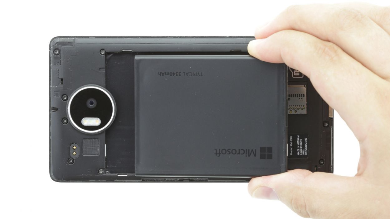
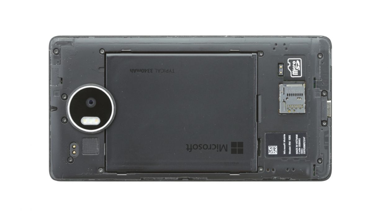
– Alright, peeps! Let’s get that battery back in place. Notice those three parallel slots on the bottom of the battery? Those are where the magic happens. Make sure the contacts align with the shiny gold ones in your device, okay? Easy peasy, lemon squeezy!
– Now, position the battery so it’s level with the enclosure. You got this!
Step 22
– Put the back cover back on.
– Use your finger to press it onto the entire frame so all the clips on the back cover click into place on the enclosure.
Step 23
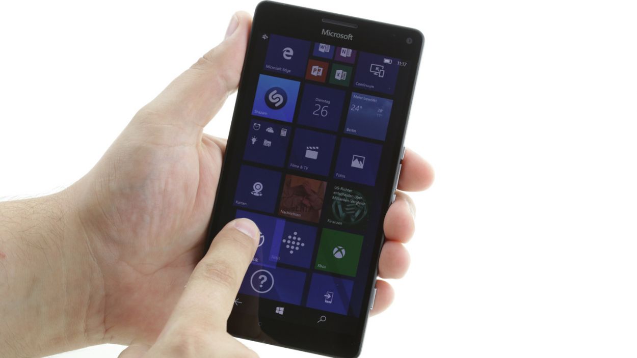
– Let’s get this party started! Turn on your device and grab any app. Now, give that app a wild ride! Drag it all the way around the screen, then zig-zag it across. If it follows your finger like a loyal puppy, you’re golden! If not, don’t worry, you can always schedule a repair.