DIY Guide to Replace Sony Xperia Z3 Compact Screen
Duration: 60 min.
Steps: 19 Steps
In this guide, we’re here to help you swap out that pesky display unit on your Sony Xperia Z3 Compact. If your screen is cracked, the touchscreen is playing hard to get, or the LCD is stuck in a black hole or flickering like a disco ball, it’s time for a change. Let’s get to it and bring your phone back to life! If you need help, you can always schedule a repair.
Step 1

Hey there! Remember to gently handle that back cover – no need for heavy-handed tactics. Carefully deal with any leftover adhesive, just like a delicate dance to avoid scratches or cracks. Keep it smooth and stylish! And if you need a hand, don’t hesitate to schedule a repair.
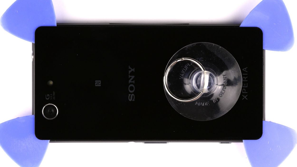
– Hey there! Let’s tackle that back cover on your Sony Xperia Z3 Compact. It’s stuck on there pretty good, but a little warmth from a heat gun will do the trick to loosen up the glue. Just a quick blast, and we’re good to go.
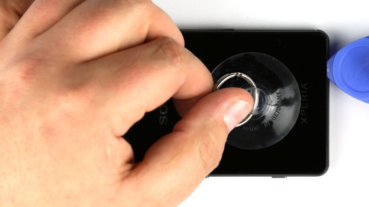
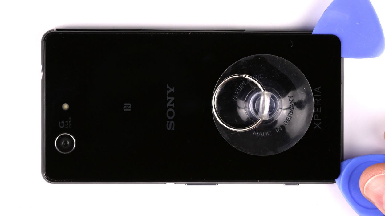
– Once you’ve heated things up, grab your trusty suction cup and stick it on the back cover. Give it a gentle tug, and voilà! You’ll see a gap forming between the frame and the cover. Now, take a pick and slide it in to keep that gap open and wide. Remember, the inside of that back cover is painted, so let’s be gentle when removing any leftover adhesive—no scratches or cracks on our watch!
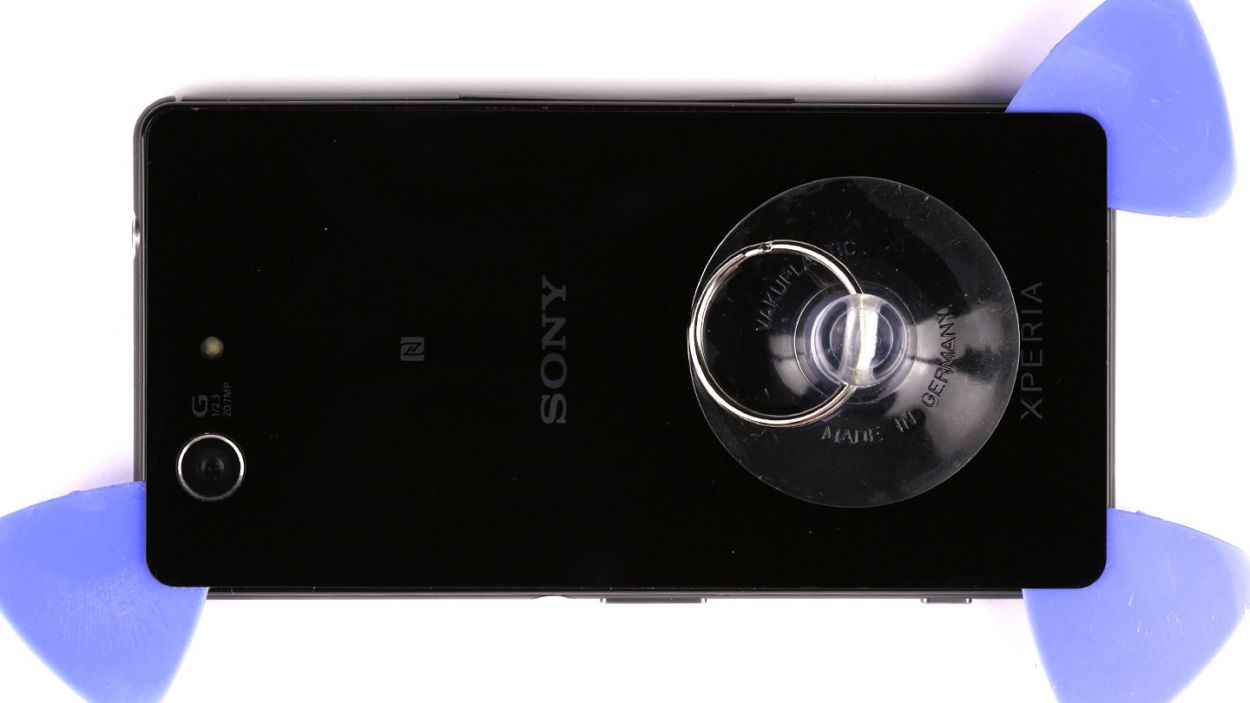
– Now, let’s get those corners loose! Use a few picks to pop up all four corners of the back cover. We’re almost there!
– Finally, carefully peel off the back cover. You’ve got this!
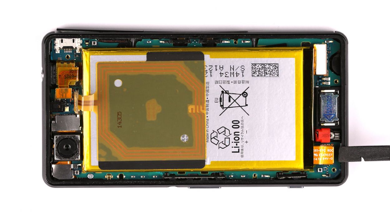
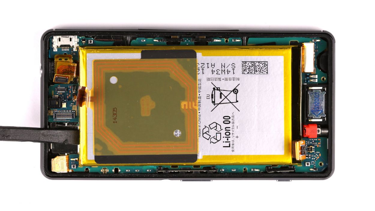
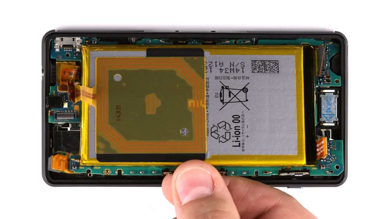
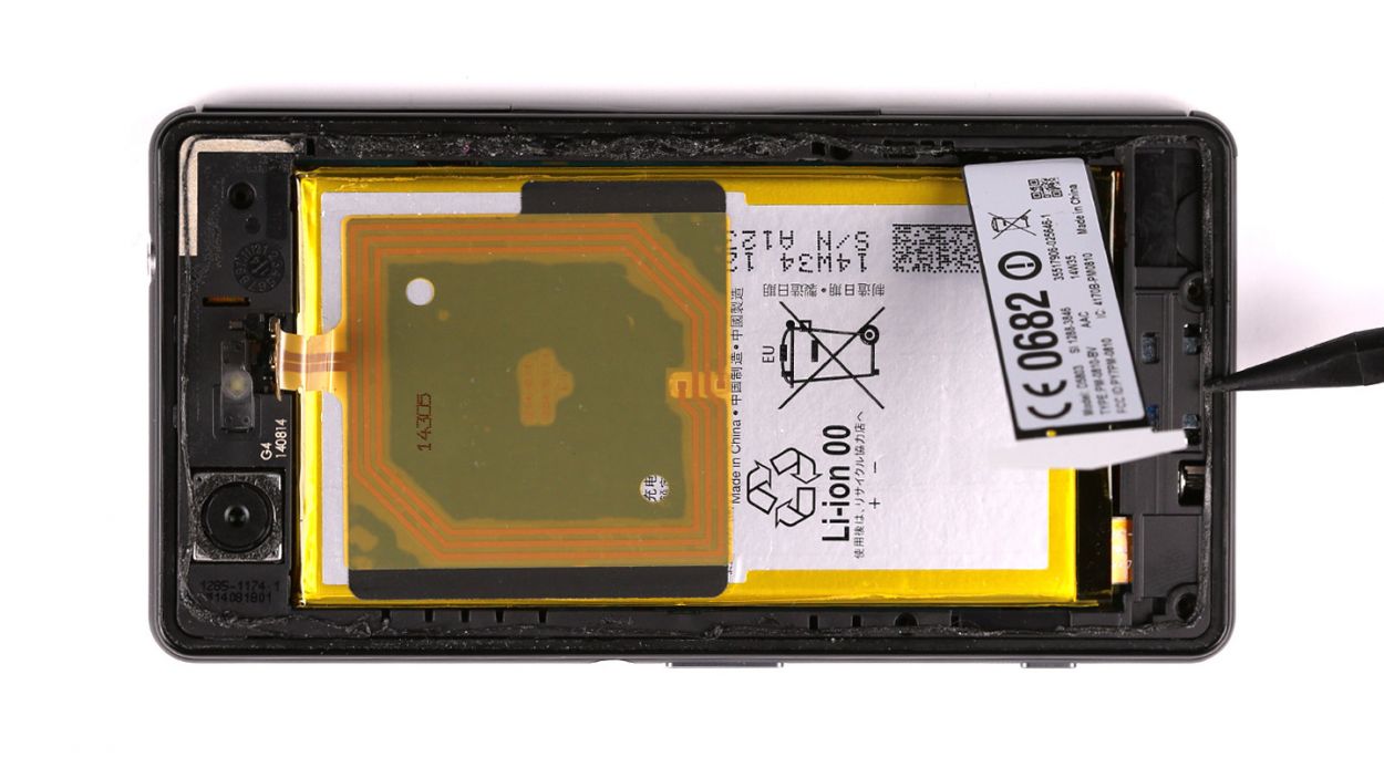
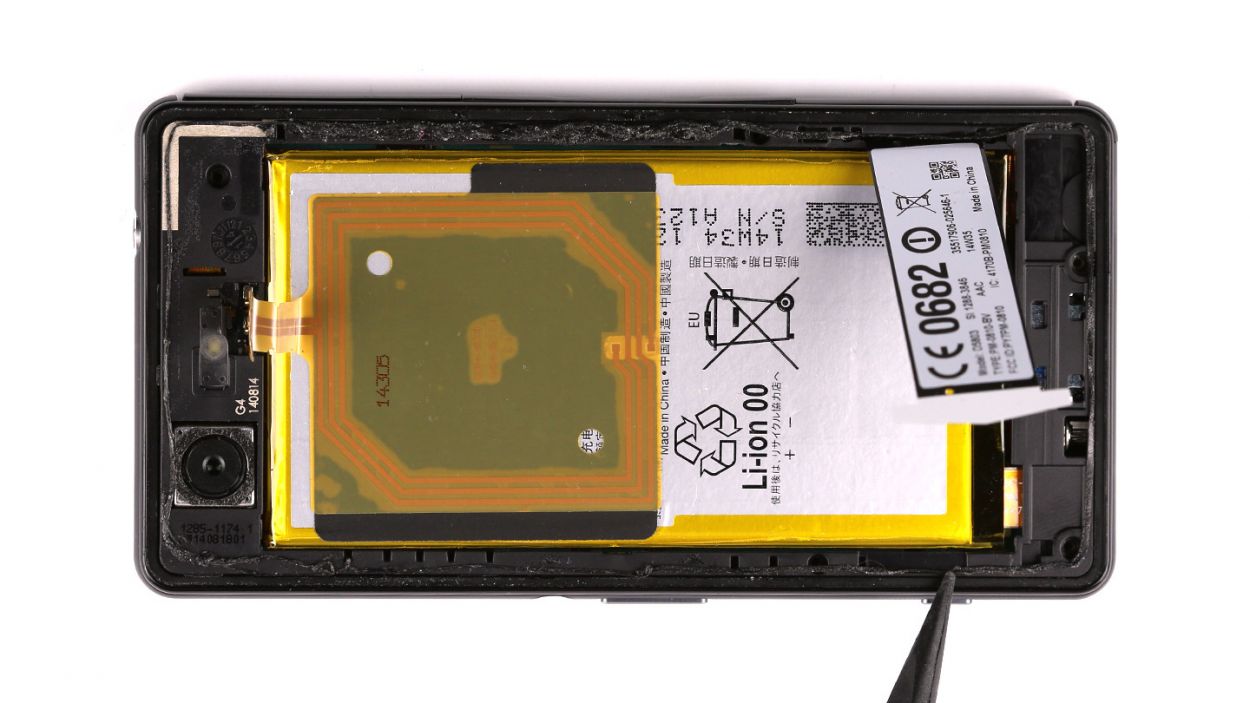
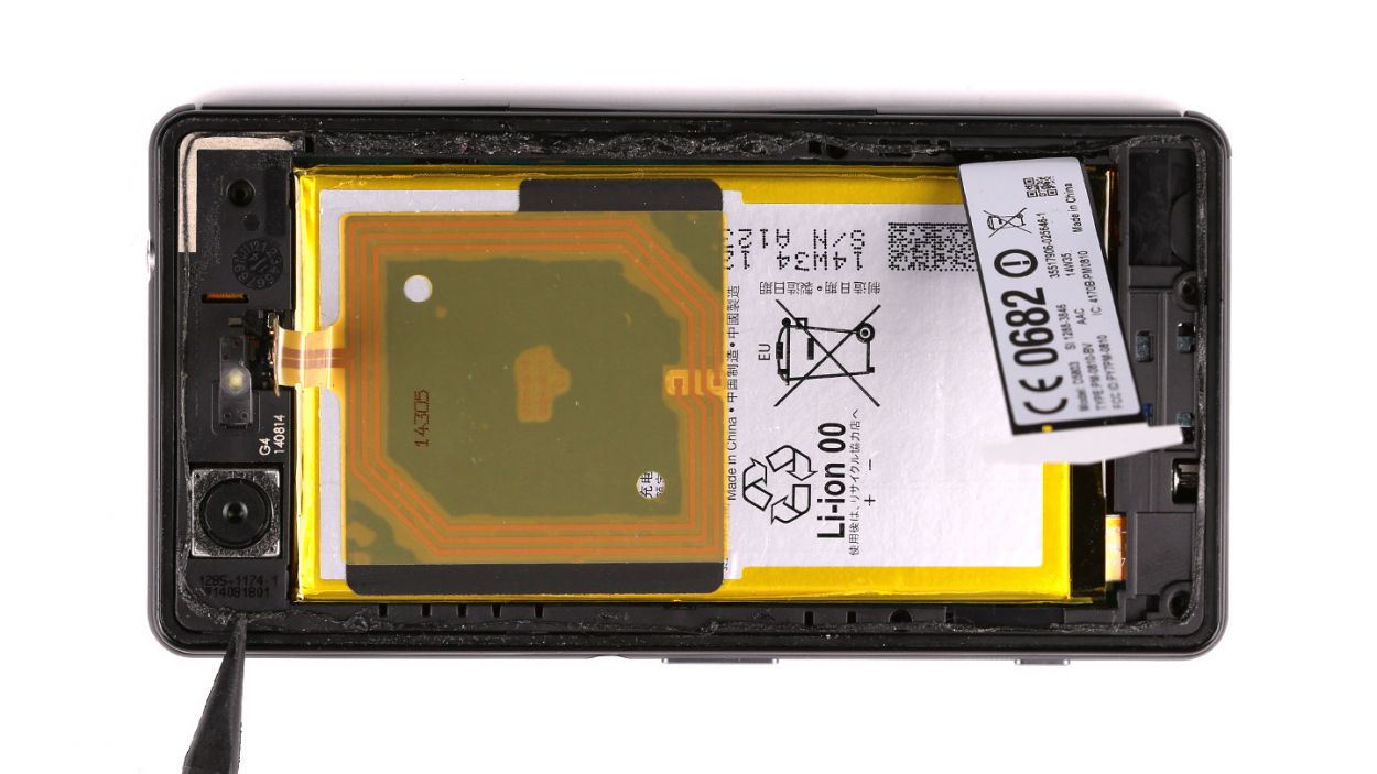
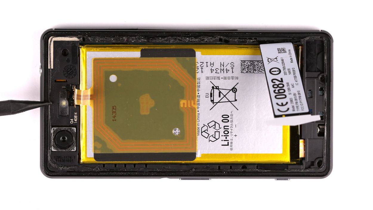
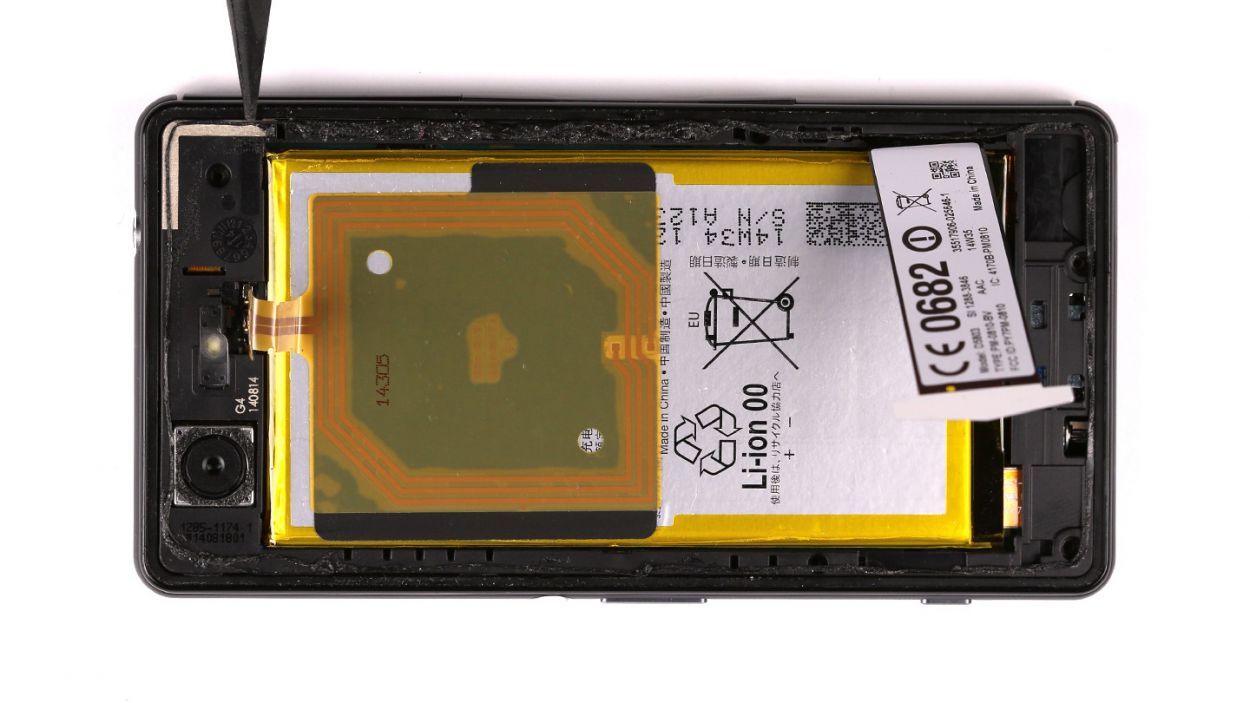
Step 2

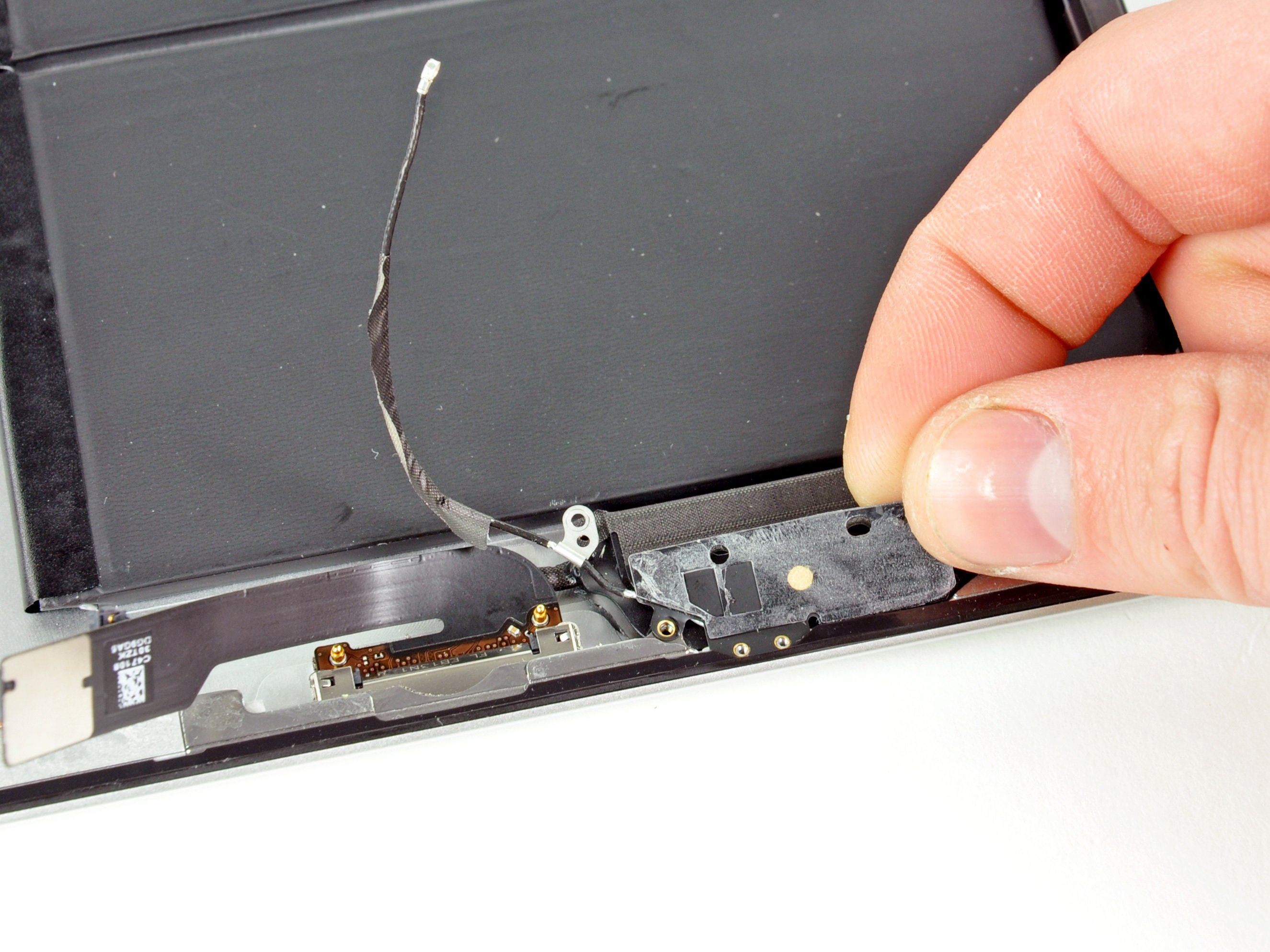
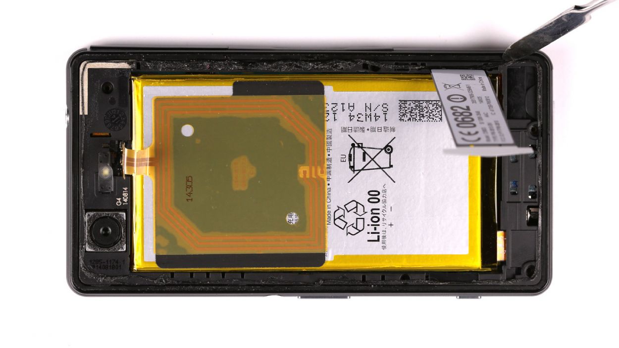
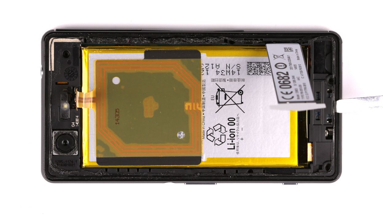
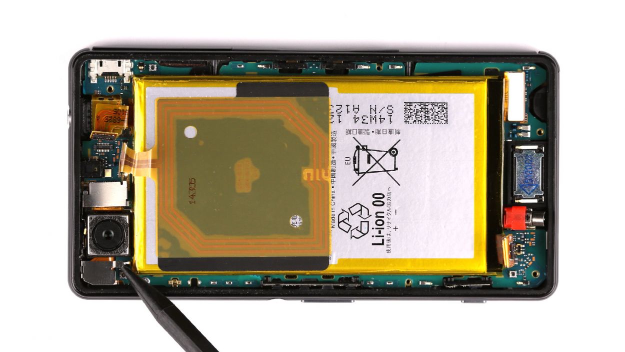
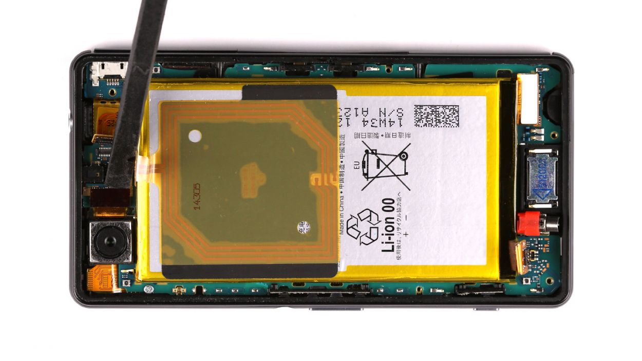
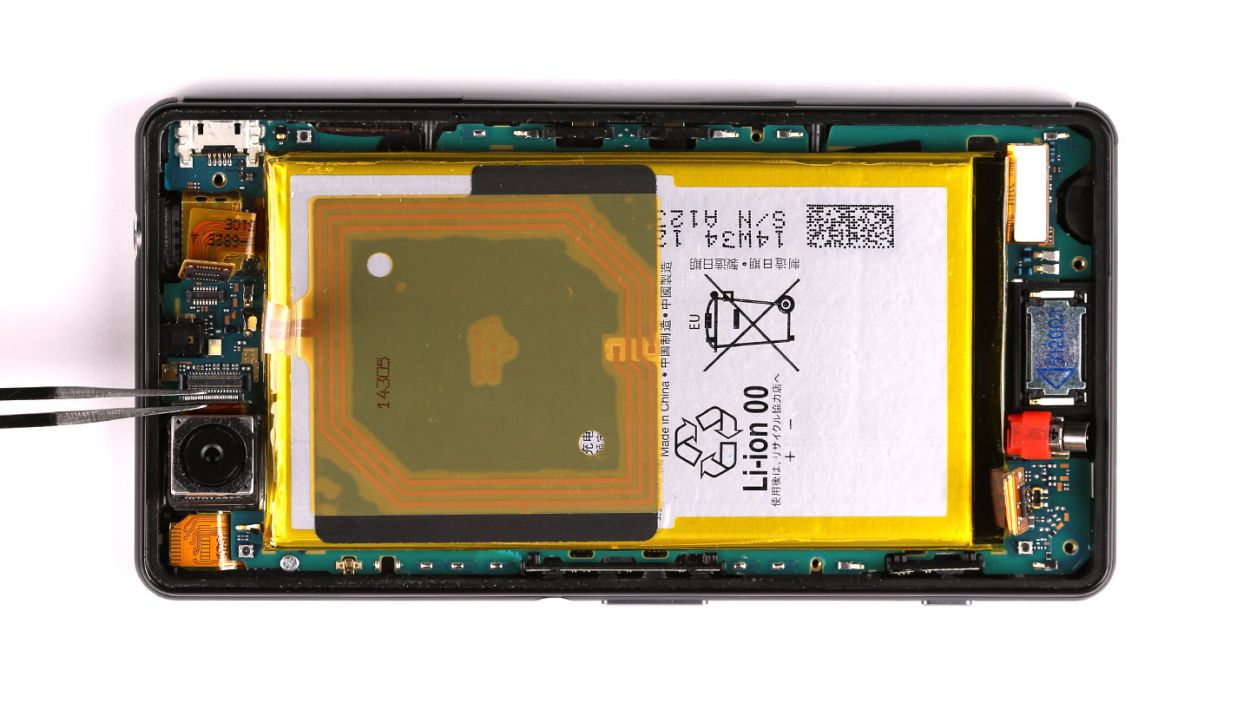
– Gently pry the NFC antenna away from the chassis using the spudger’s pointy end. It’s like giving the antenna a little nudge to freedom!
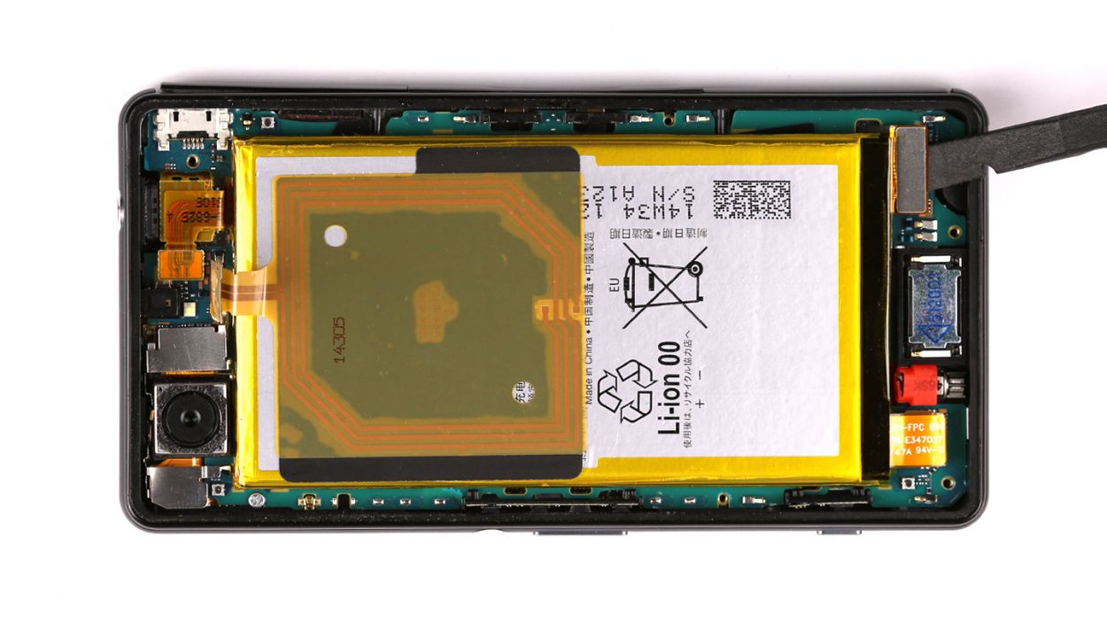
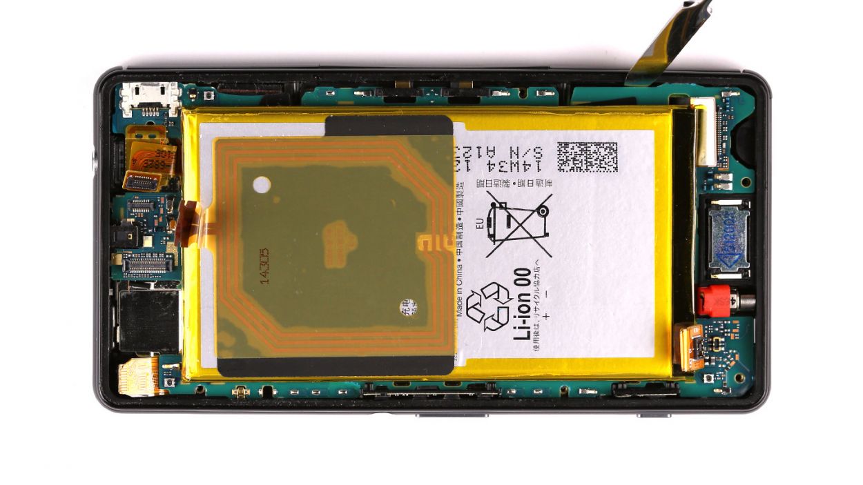
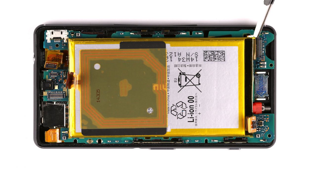
Step 3
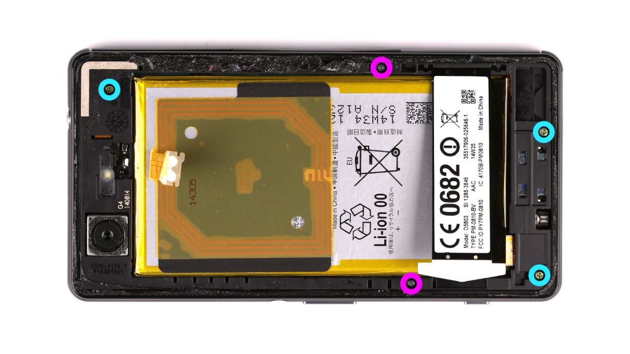
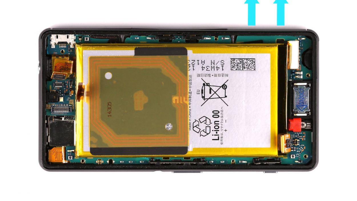
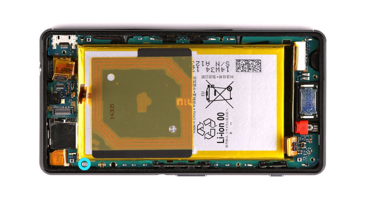
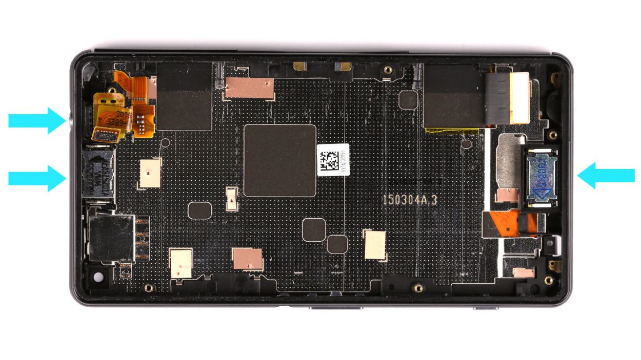
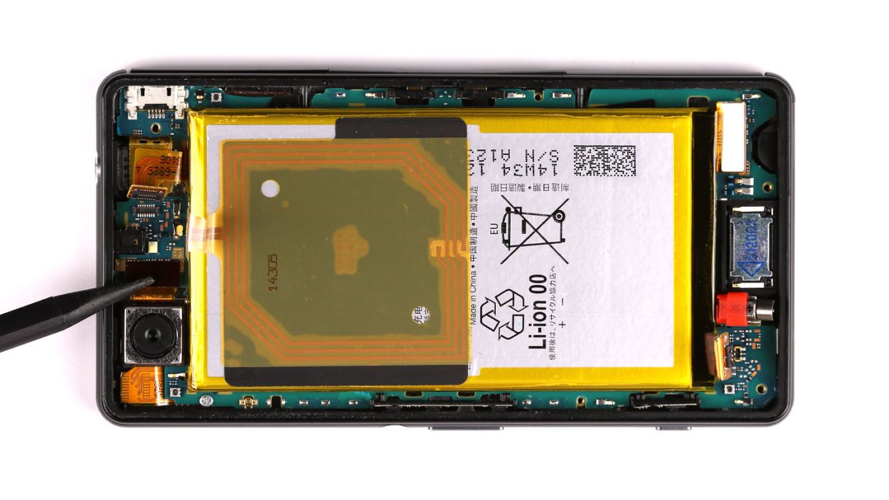
– Let’s get those screws out! First, grab your trusty Phillips head screwdriver and remove the five screws holding the chassis together. There are three 3.3mm screws and two 3.7mm screws – easy peasy! If you need help, you can always schedule a repair
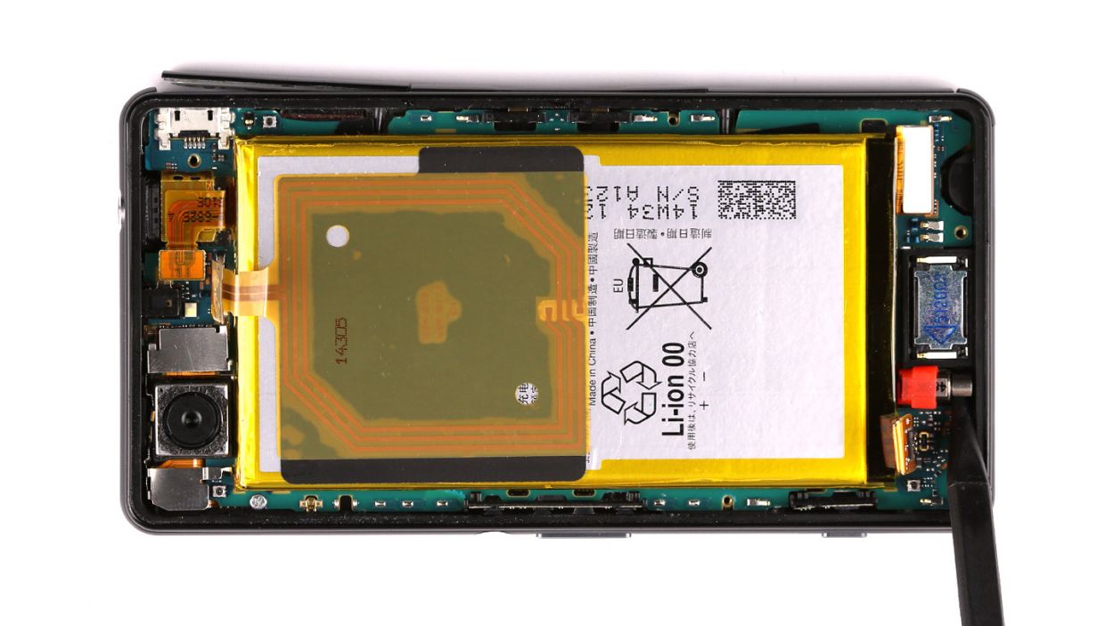
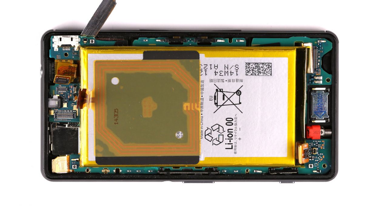
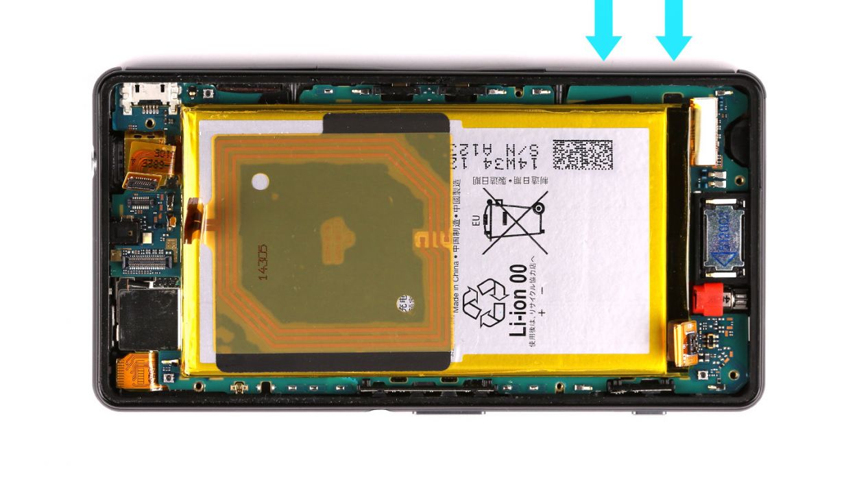
Step 4

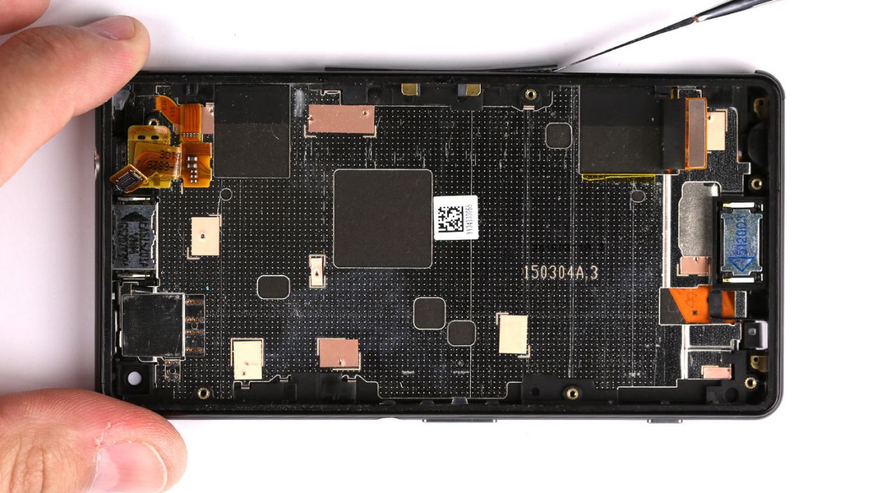
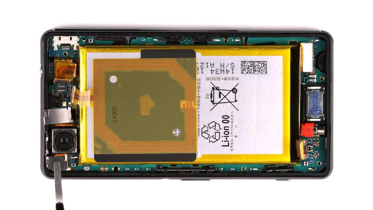
– Time to get started. Begin by carefully inserting the steel laboratory spatula between the chassis and the enclosure to release them from their cozy connection.
– Now, work your way around the enclosure with the steel spatula, repeating the process until the chassis is free.
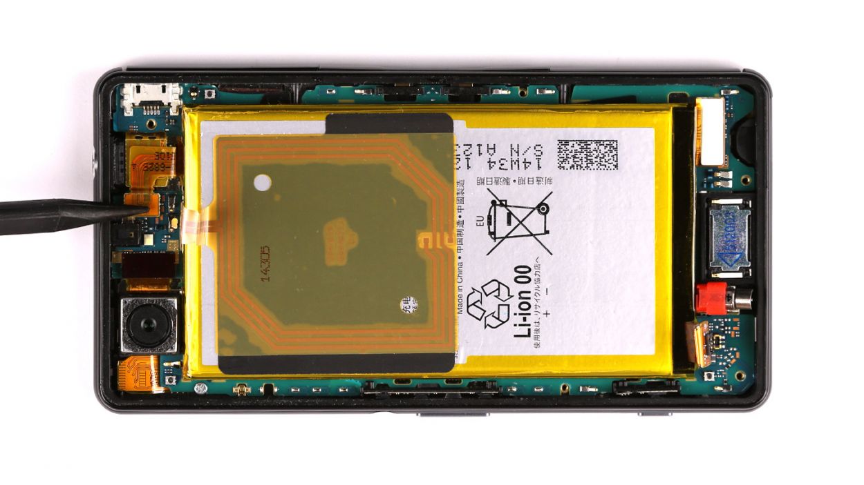
– Once you’ve successfully detached the chassis, go ahead and remove it. You’re making great progress! If you need help, you can always schedule a repair.
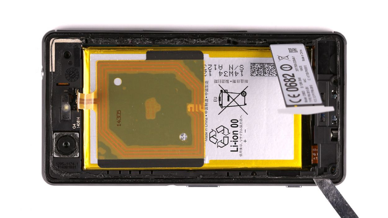
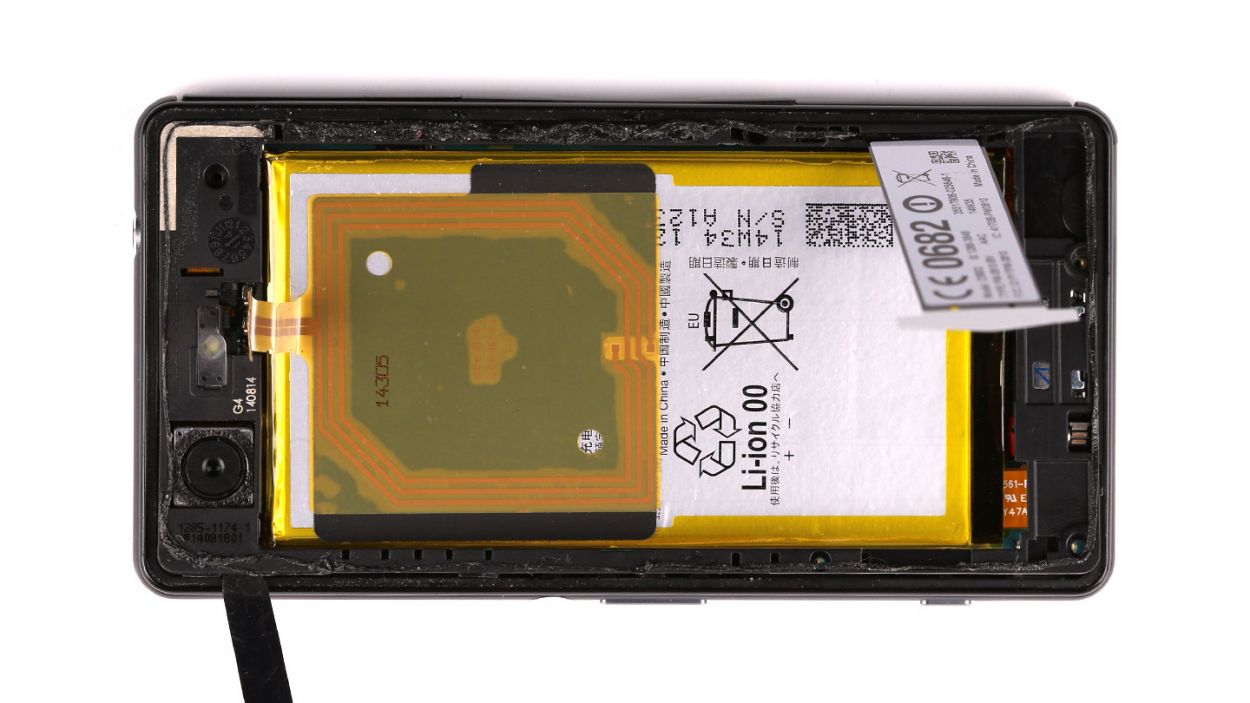
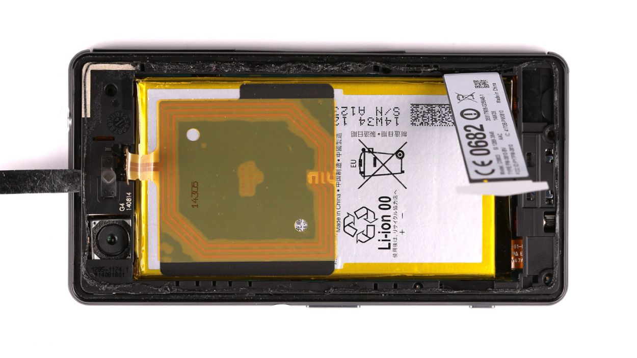
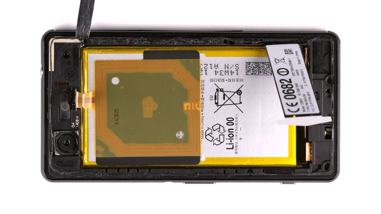
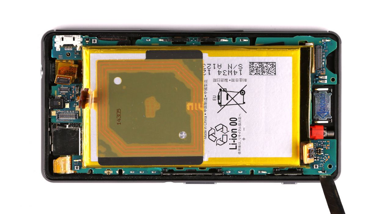
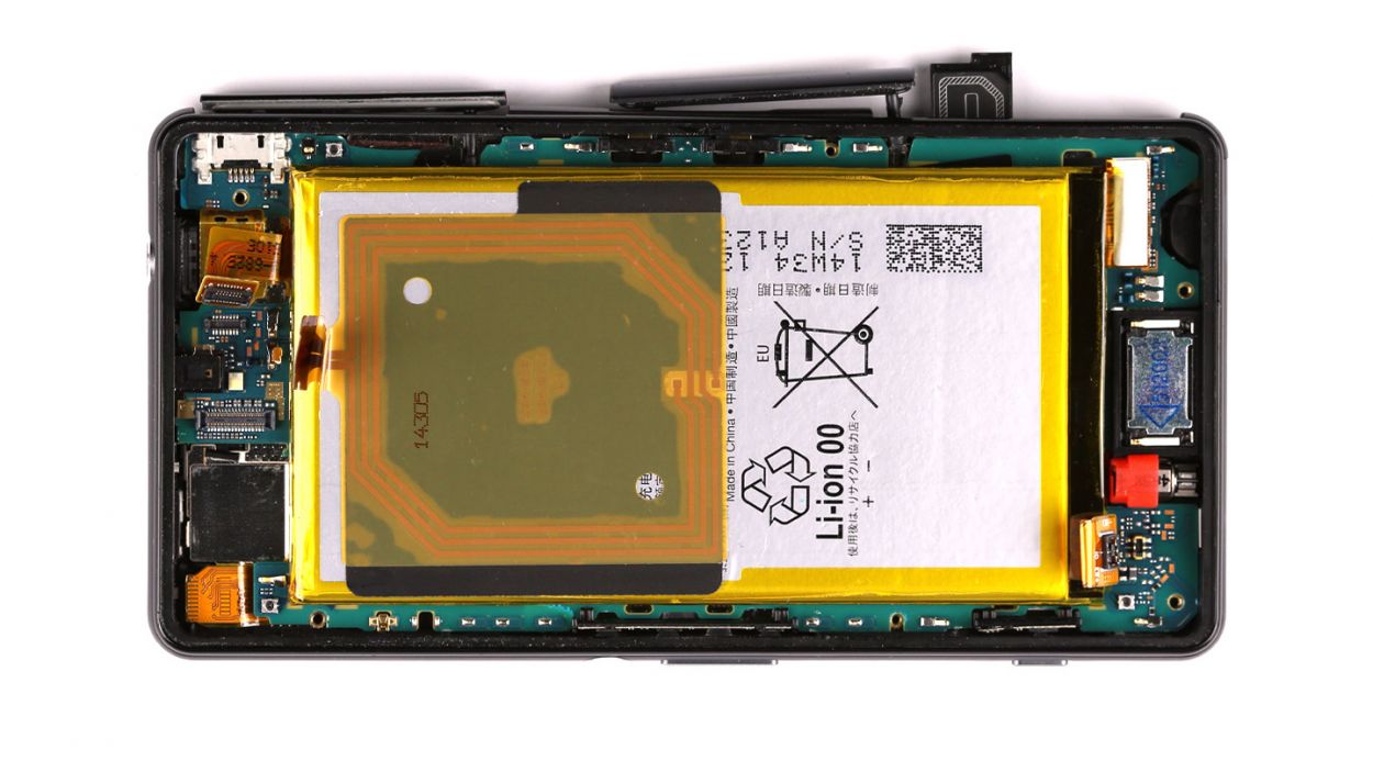
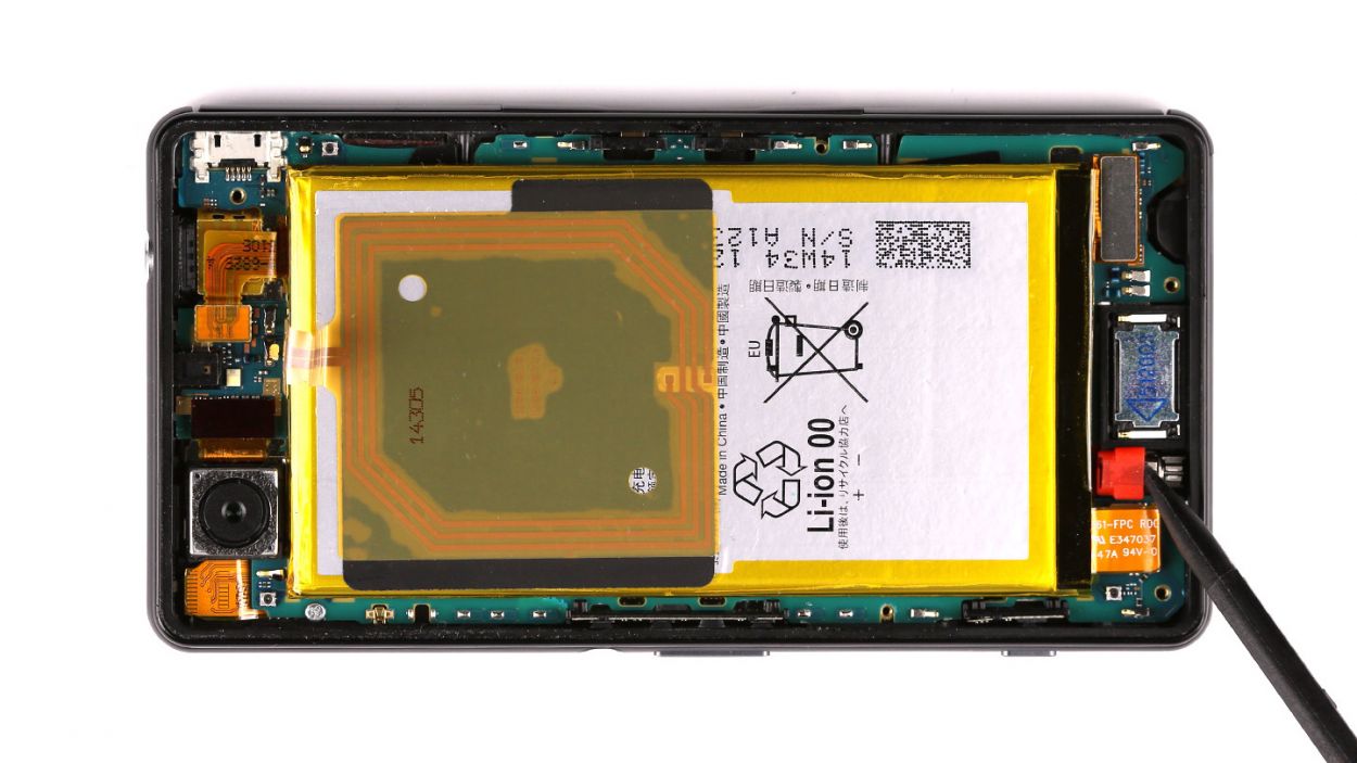
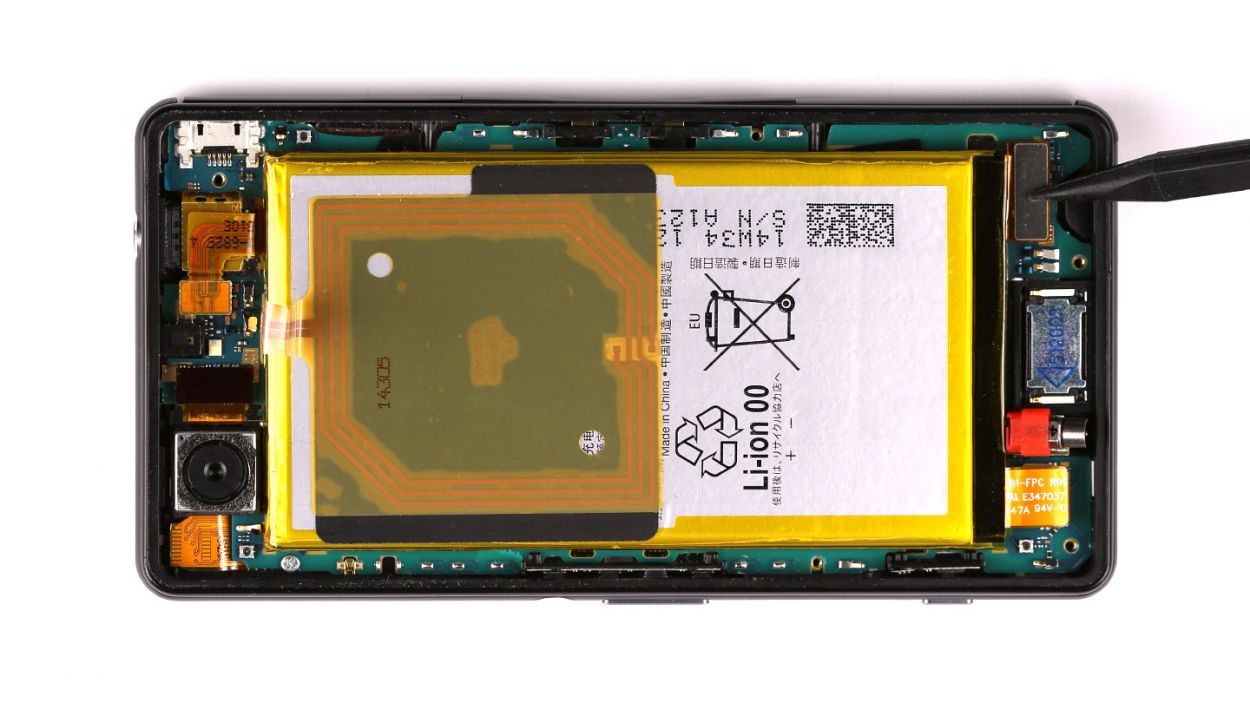
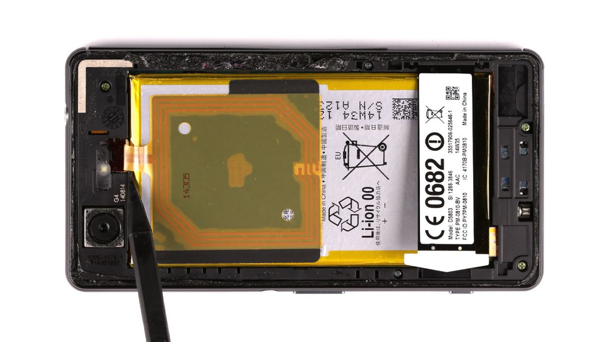
Step 5
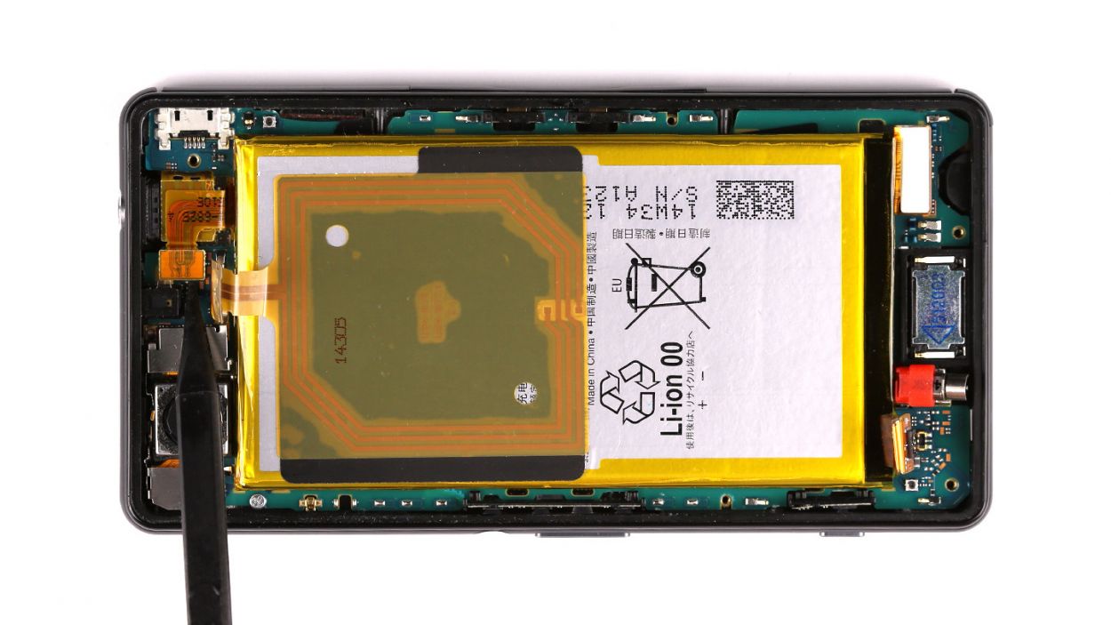
– Alright, let’s get those connectors out of the way! Start by gently unplugging the battery connector—take care not to tug too hard on the logic board. We don’t want any surprises.
– Next, it’s time to unhook the flexible flat display cable. Just a little wiggle and you’ll have it free.
– Now, let’s detach the vibrator motor. Again, a gentle touch is all you need here.
– Finally, disconnect the headphone jack. And just like that, you’re making progress!
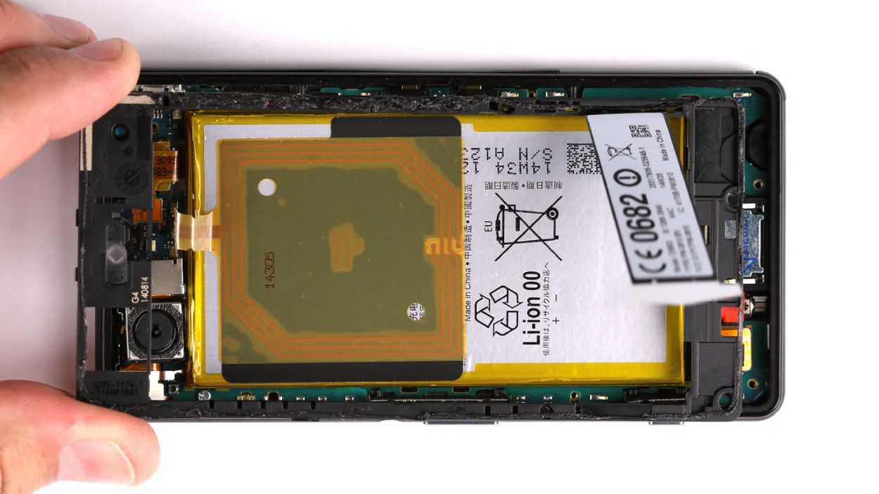
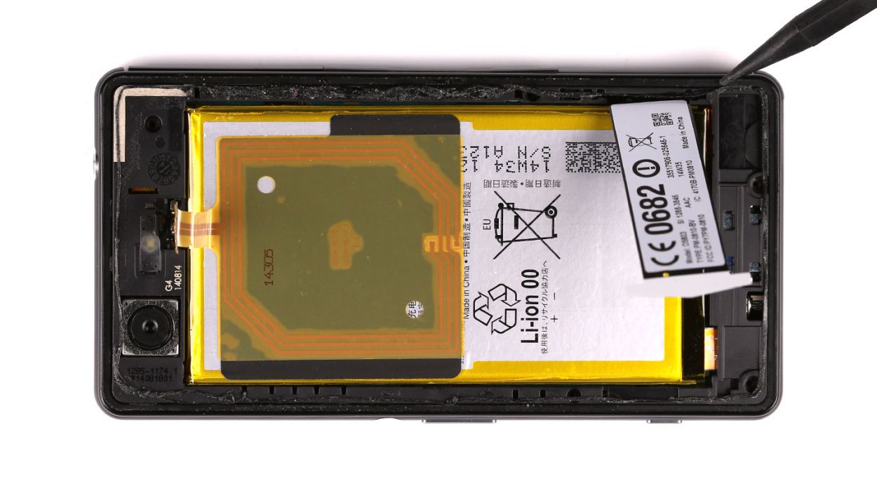
Step 6


– Let’s gently unclip that camera bracket – easy peasy!
– Grab your tweezers and give that bracket a little nudge. No sweat!
– Time to disconnect the rear camera from the logic board. Piece of cake!
– And with that, the rear camera is free! High five!
Step 7

– Let’s get those SIM and microSD cards out! They’re tucked away under a little cover.
– Pop off that cover and grab those cards. The microSD card’s got its own special spot.
Step 8
– Time to get bold! Remove that 1 x 2.3 mm Phillips screw holding the logic board in place. Trust us, it’ll be a breeze!
Step 9


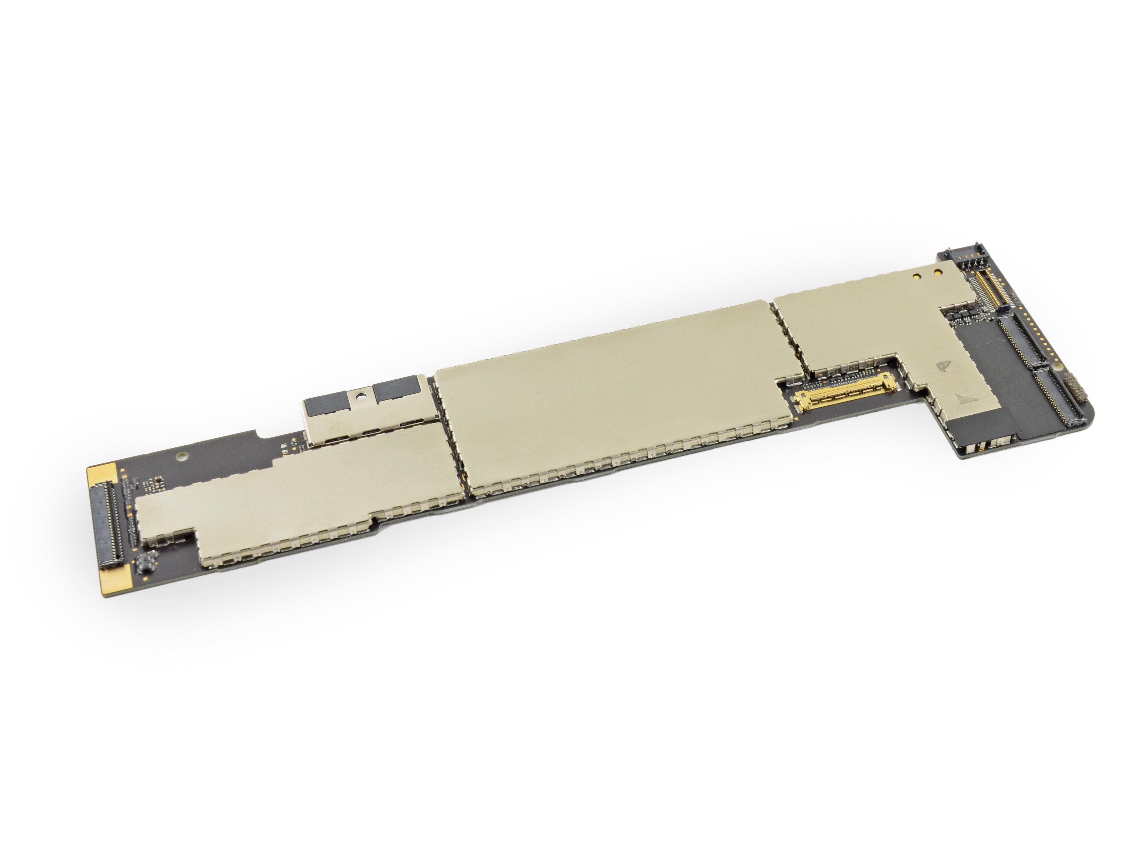
– Gently coax the logic board out of its cozy home using a spudger—just a little nudge will do!
– Once the logic board is free, carefully guide that display cable through the little opening in the logic board.
– Now, go ahead and remove the logic board completely. You’re doing great!
Step 10
– Your shiny new display might be missing some parts, but no worries! Just swap them over from your old one.
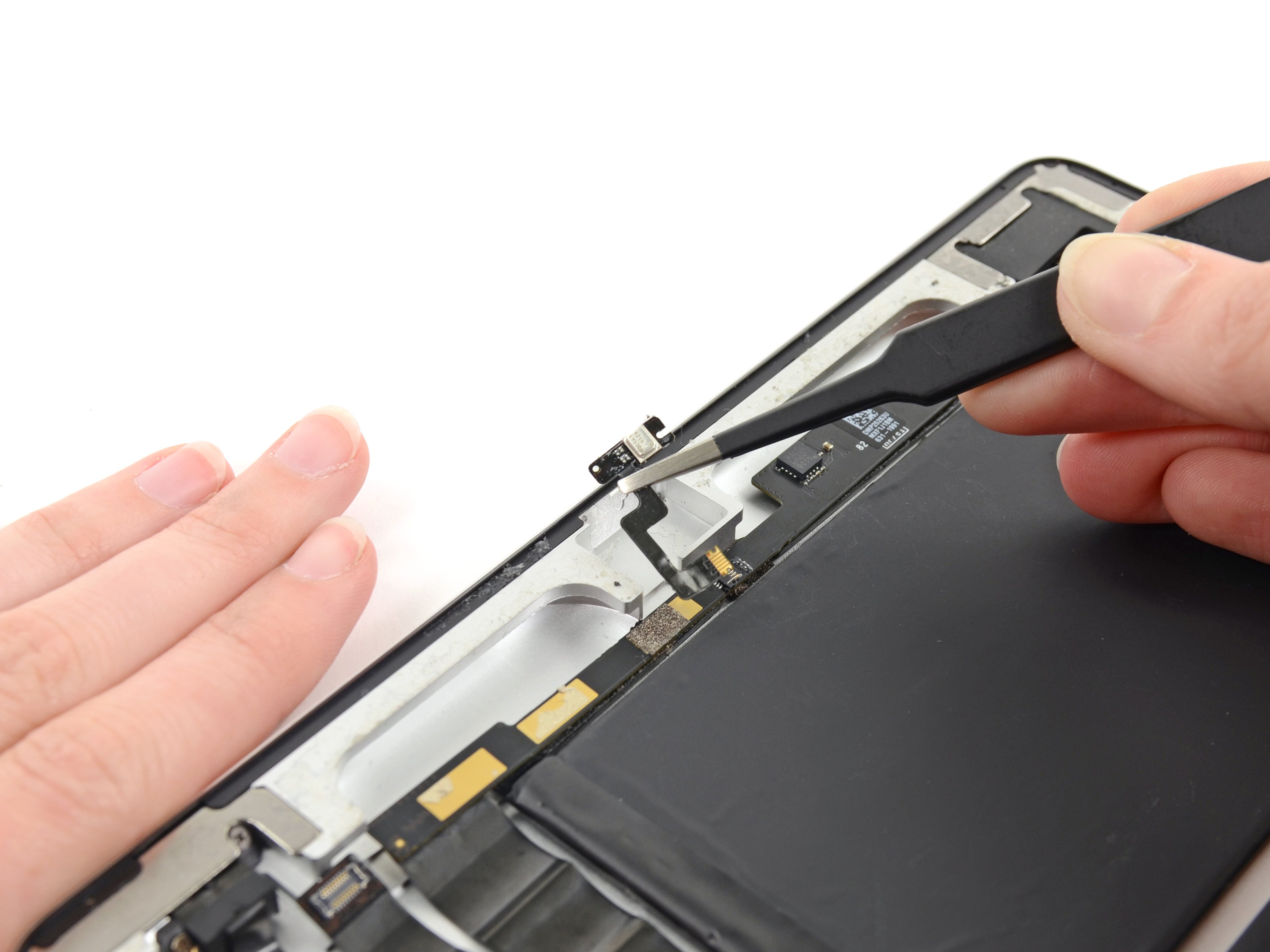
– Time to get serious—gently take out the two speakers, the headphone jack, and those three covers.
– For the USB port and SIM/microSD card slot, just pop off the covers with a little push. Easy peasy!
– Use a steel spatula to carefully lift the cover for the magnetic charger contact. A little heat can help loosen it up first!
Step 11
– Gently place the logic board into its cozy home in the enclosure.
– Carefully thread the display cable through the little opening in the logic board, like a pro!
Step 12

– Get that logic board snugly fitted in place with a trusty Phillips screw. Just one 2.3 mm Phillips screw is all you need to keep it secure!
Step 13
– Put the SIM card and the microSD card back in your device. Both cards are hidden under a cover.
– Take off the cover and put in the cards. The microSD card has its own tray.
Step 14
– Gently place the rear camera snugly into its cozy little home in the enclosure.
– Connect the camera to the logic board like a pro, ensuring a solid link.
– Fasten the camera down with the metal bracket, securing it in place for a job well done!
Step 15

– Plug in the headphone jack like a pro.
– Make sure the vibrator motor is snugly back in its original home.
– Attach the flexible flat display cable to the logic board with care.
– Connect the battery and power up!
Step 16
– Gently set the chassis onto the enclosure, just like placing a cozy blanket on your favorite chair.
– Now, give the chassis a little love tap all around the edges to make sure it clicks snugly into the enclosure. It’s like a warm hug for your device!
Step 17

– Attach the chassis to the enclosure with the 5 Phillips screws.3 x 3.3 mm Phillips screws2 x 3.7 mm Phillips screws
Step 18
– Attach the NFC antenna to the chassis by connecting it at its contact point.
Step 19
– Pop that back cover back on! Give it a good press around the edges to make sure those adhesive surfaces are sticking like best friends.
– Warm up that back cover a bit to help the glue do its thing and stick better. If you’re feeling fancy, you can clamp it down and let it chill for a while so the glue sets perfectly.