
DIY Guide to Replace Sony Xperia Z3 Display
Duration: 60 min.
Steps: 19 Steps
In this guide, we’re here to help you tackle the replacement of your Sony Xperia Z3’s display unit all by yourself! If you’re dealing with a cracked glass, an unresponsive touchscreen, or an LCD that’s gone dark or is flickering, it’s time to roll up your sleeves and get to work. And remember, if you need help, you can always schedule a repair!
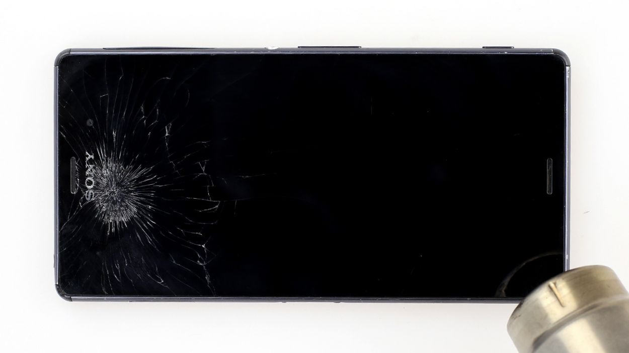
Step 1
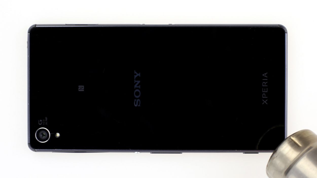
– Get ready to liberate the back of your Sony Xperia Z3’s enclosure! It’s glued on tight, but a heat gun will help soften that stubborn adhesive. Just be patient and keep heating until it’s ready to come off.
– We know, we know – the gap between the aluminum frame and the glass is teeny-tiny. That’s why we recommend using a super flat, sturdy object to get in there and help things along.
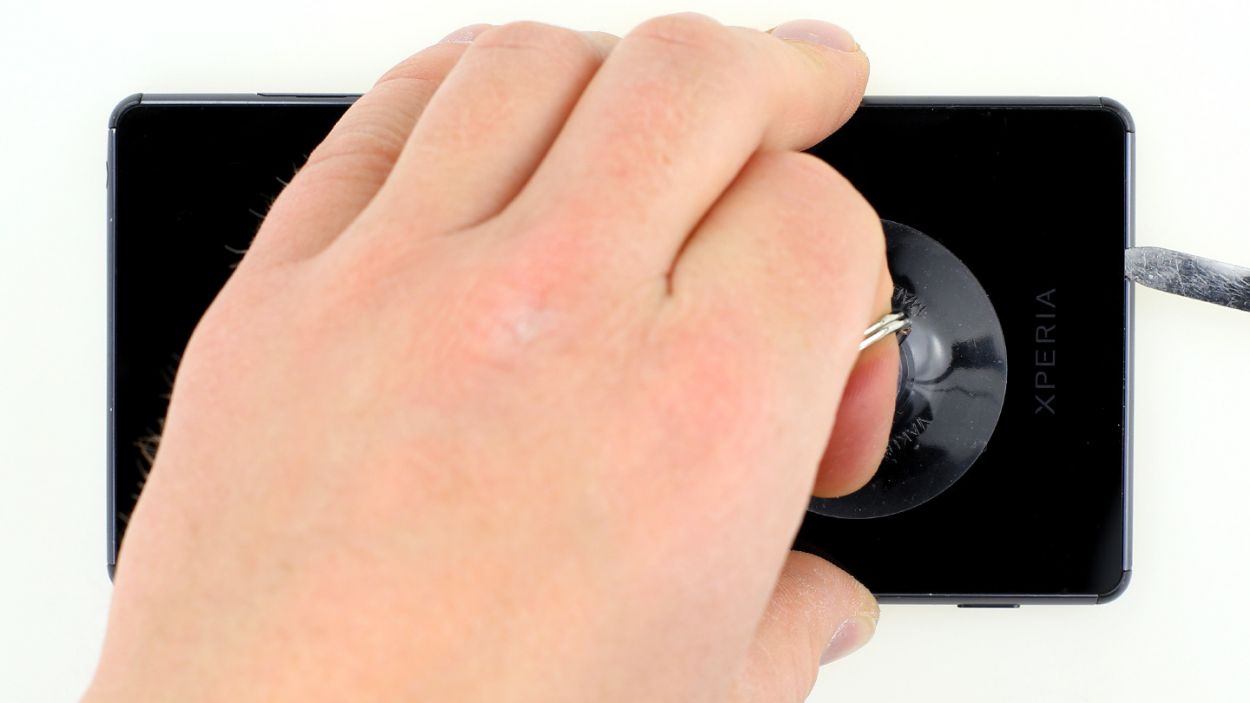
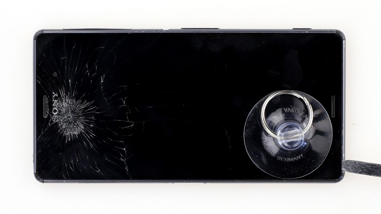
– Now it’s time to carefully pry open that back cover. Use a suction cup to get a good grip, and don’t be afraid to take your time.
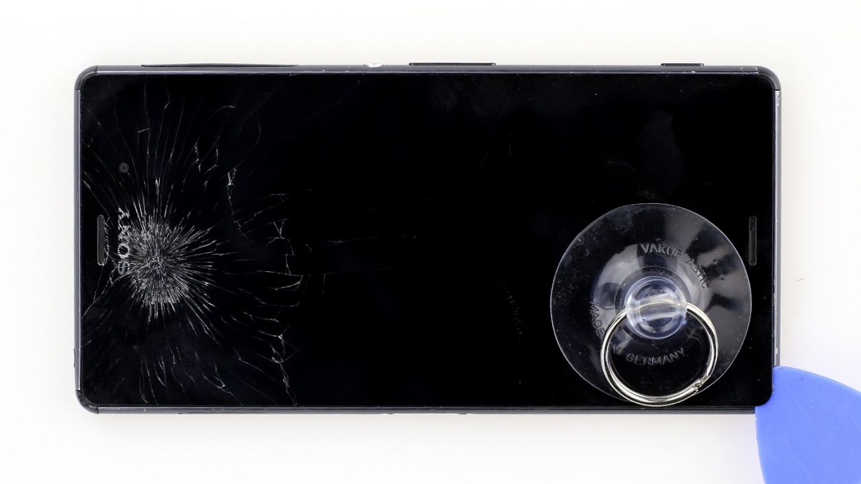
– As soon as you see a glimmer of hope (aka a small gap), grab your trusty plastic pick and use it to gently coax the back cover open. Remember, you’re in control – don’t let that aluminum get damaged!
Step 2
The inside of the back cover has a fresh coat of paint! Gently remove any sticky residue to keep it looking sharp and avoid any scratches or cracks. You’ve got this!
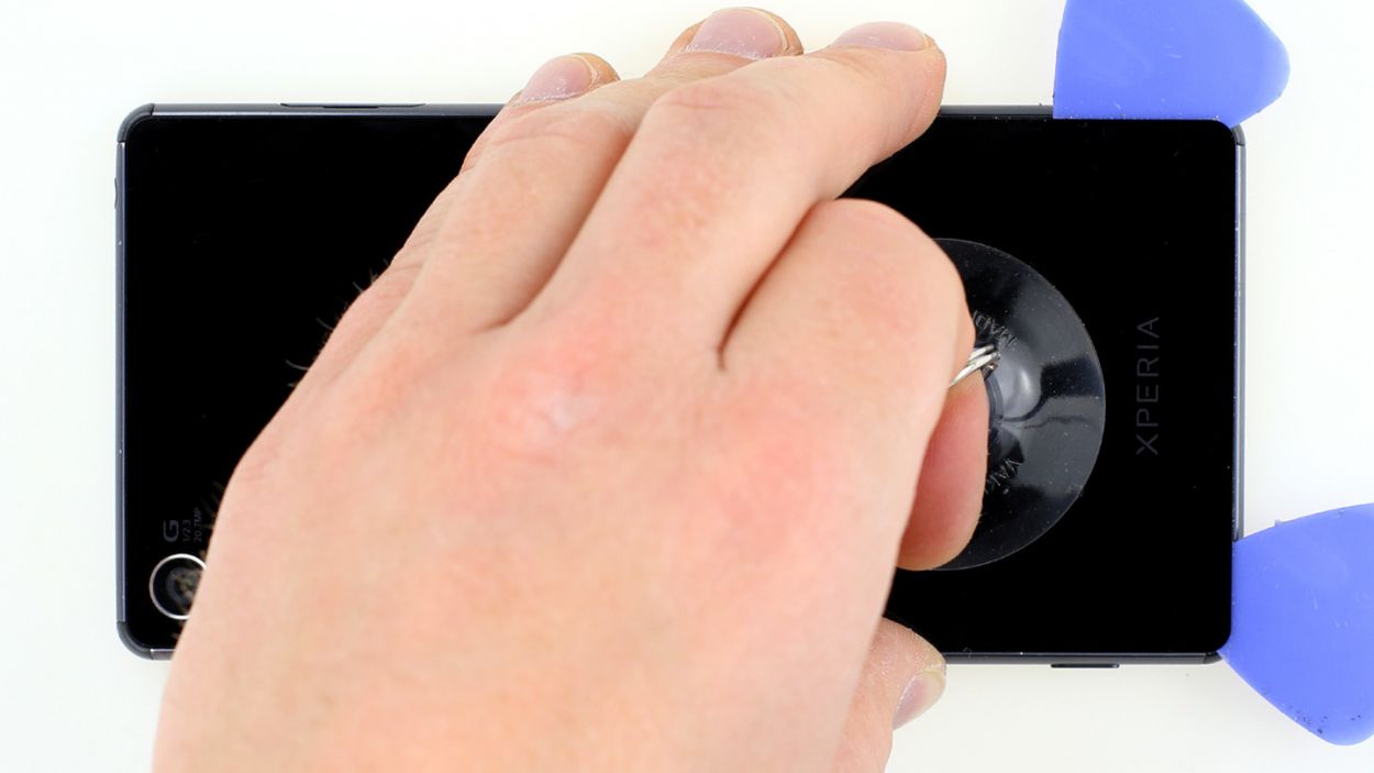
– Gently slide the pick just a few millimeters between the back cover and the frame—this way, you’ll keep the inner workings safe and sound! Remember, the back cover has a paint job on the inside, so be extra careful when removing any sticky residue to avoid scratches or cracks.
– The back cover of your Sony Xperia Z3 is glued all around the outer edge, so take your pick and make a full circle around the phone. Don’t forget, there are also two sneaky adhesive+strips+Xperia+Z3&crid=1TJIMMAJSUJUZ&sprefix=repair+tools%2Caps%2C165&linkCode=ll2&tag=salvationrepa-20&linkId=c486487cf454ce8edd6f5beefab4110f&language=en_US&ref_=as_li_ss_tl’>adhesive strips stuck to the battery that won’t budge until you lift the top.
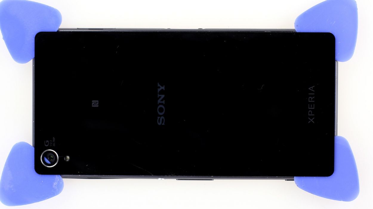
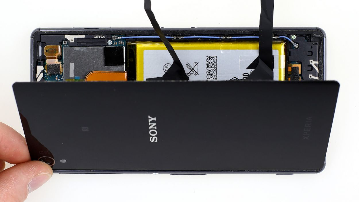
– After you’ve tackled all that glue, you can gently lift off the back cover. You’re almost there!
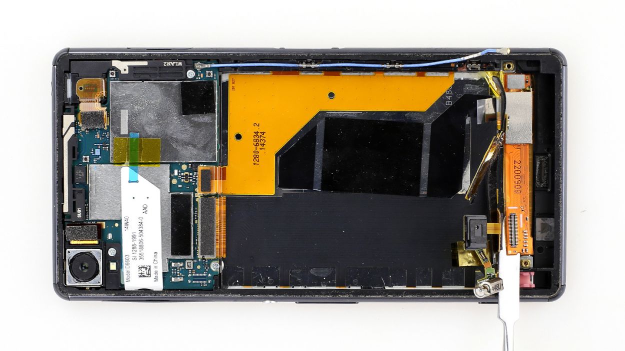
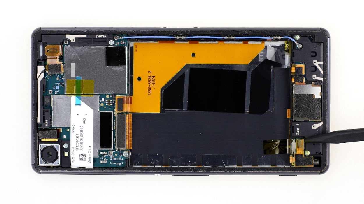
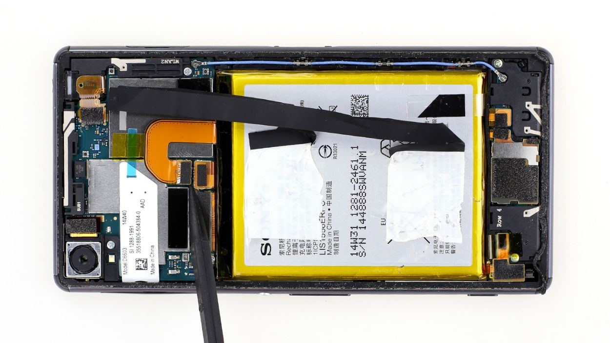
Step 3


– Gently nudge the spudger’s tip under that contact – think of it as a tiny lever! Lift it up with care; those little resistors are delicate darlings.
– Now, give that battery a little lift. It’s just chilling there, lightly glued in place. Easy peasy!
– And that’s it! Battery removal complete. Feeling good? If you need a hand with anything, you can always schedule a repair
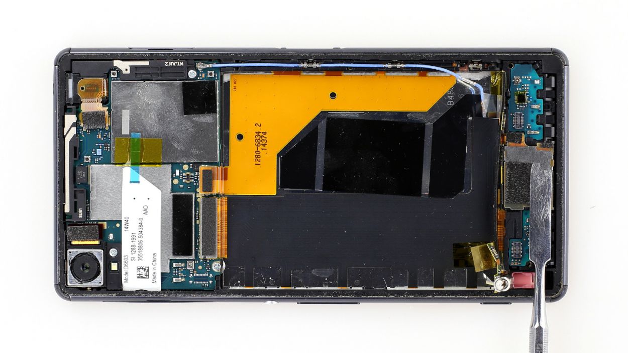
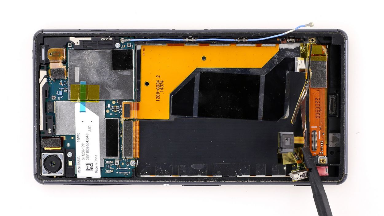
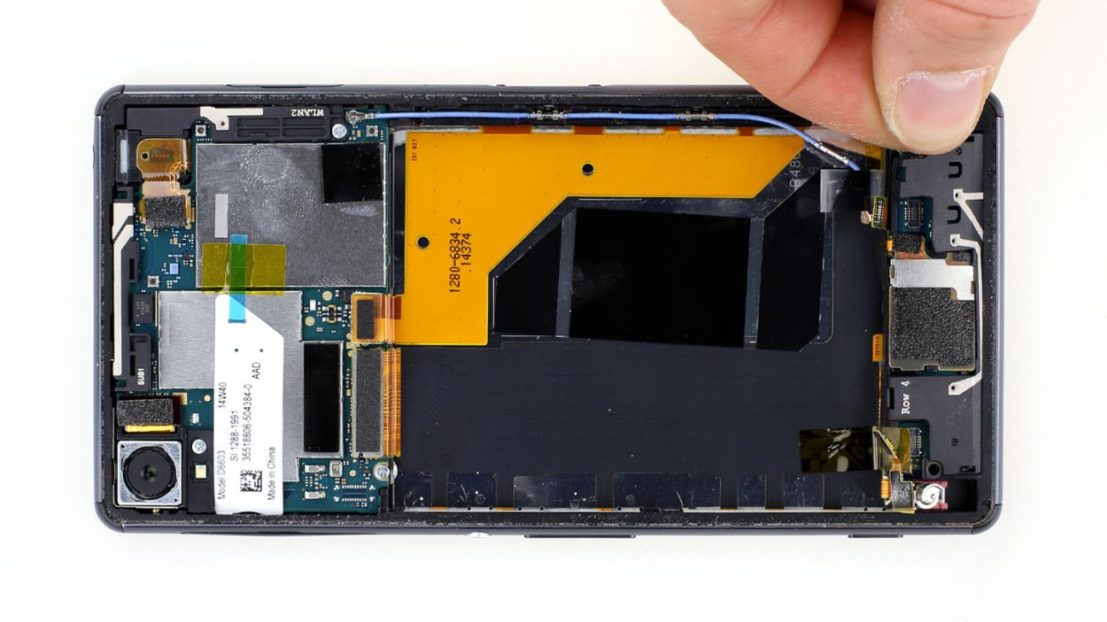
Step 4


– First up, let’s peel off that clear protective film covering the vibration motor’s connector. Grab your trusty spudger and gently slide the pointed tip just below the contact, then give it a little lift.
– Next, it’s time to disconnect the sub-board from the logic board. You got this!
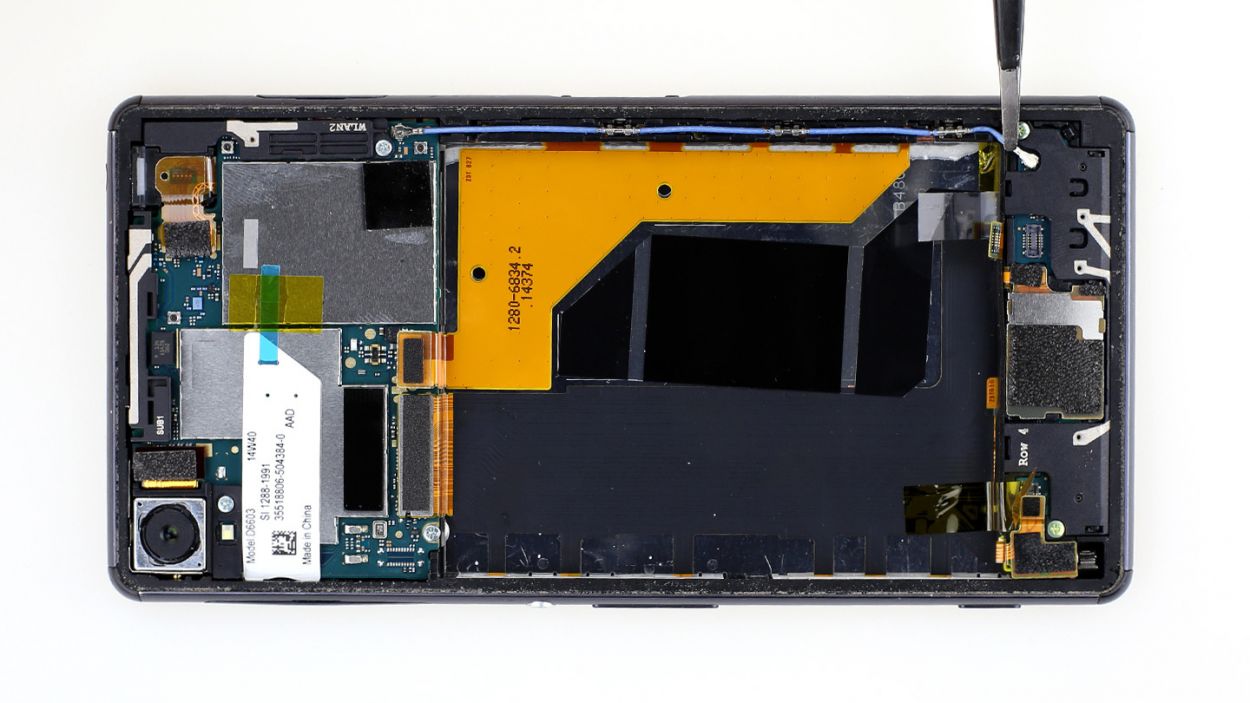
– And don’t forget, you still need to detach the antenna connection cable. Almost there!
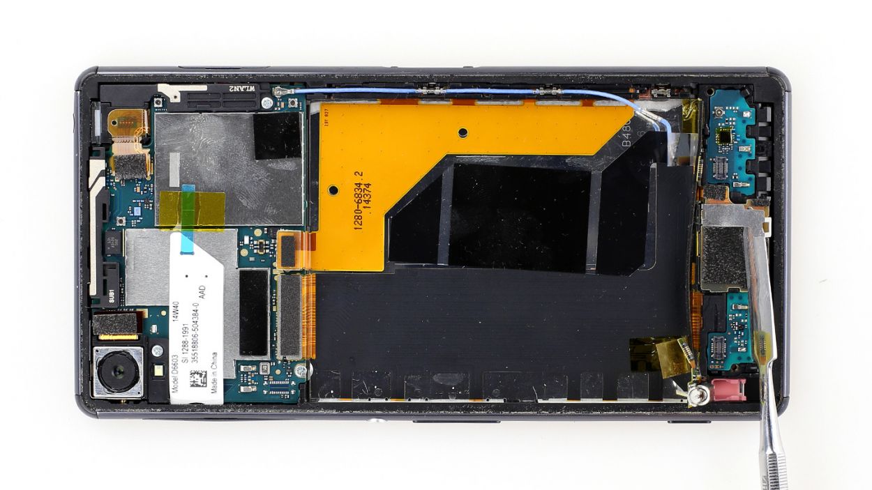
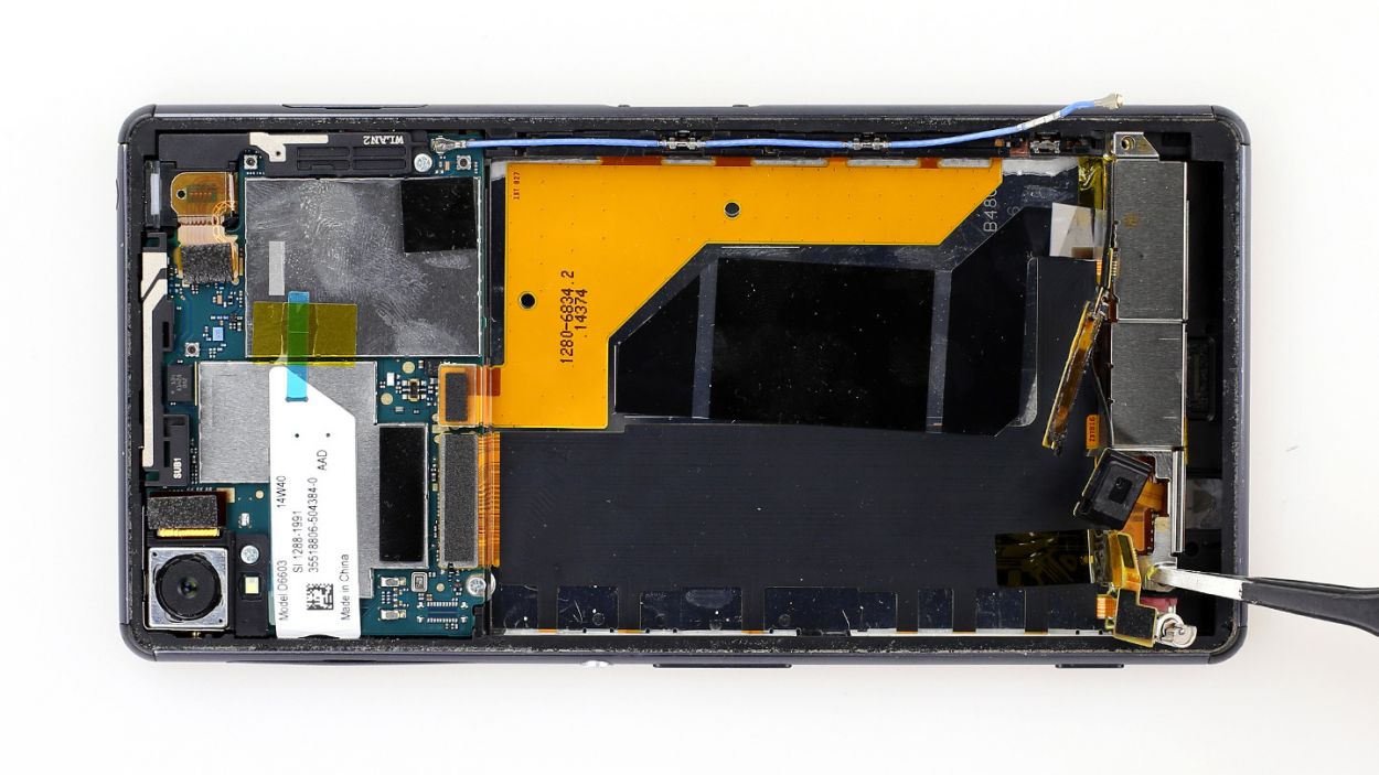
Step 5
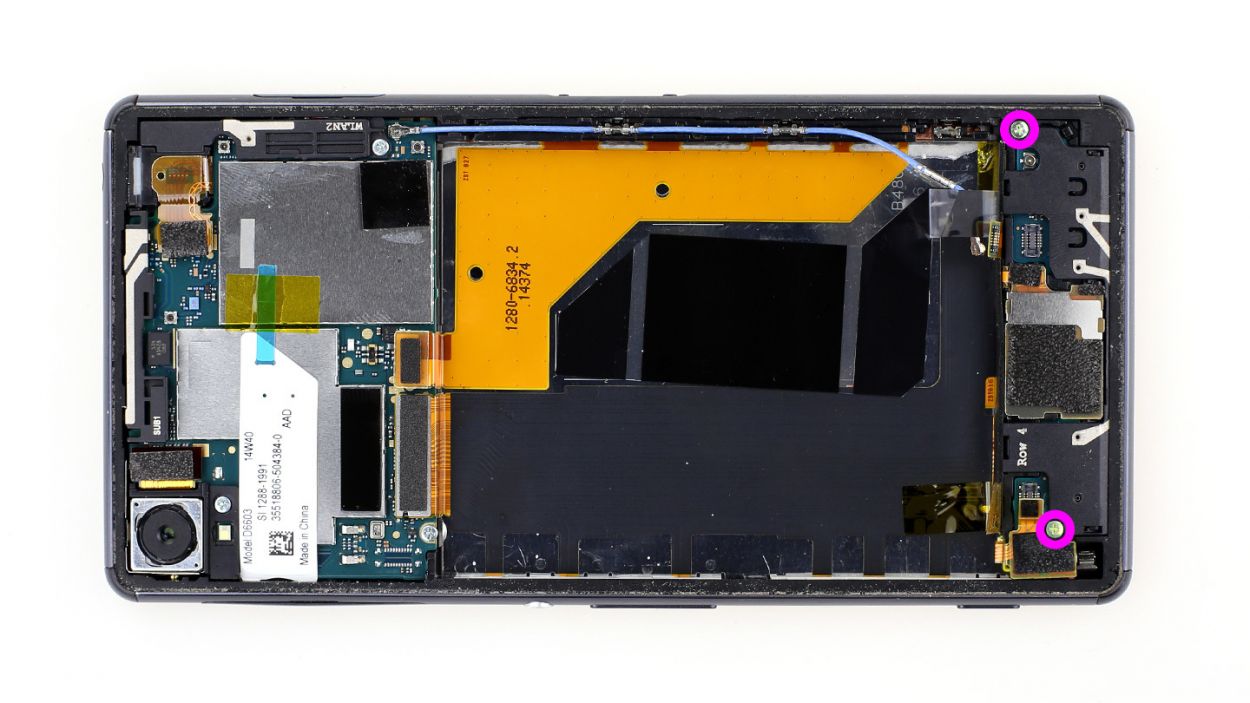

– First things first, let’s get that black plastic cover off before we dive into the sub-board! It’s held in place with screws and is snugly fit between the frame and the board.
– Unscrew those two Phillips screws. We’re talking about 2 x 3.3 mm Phillips screws here.
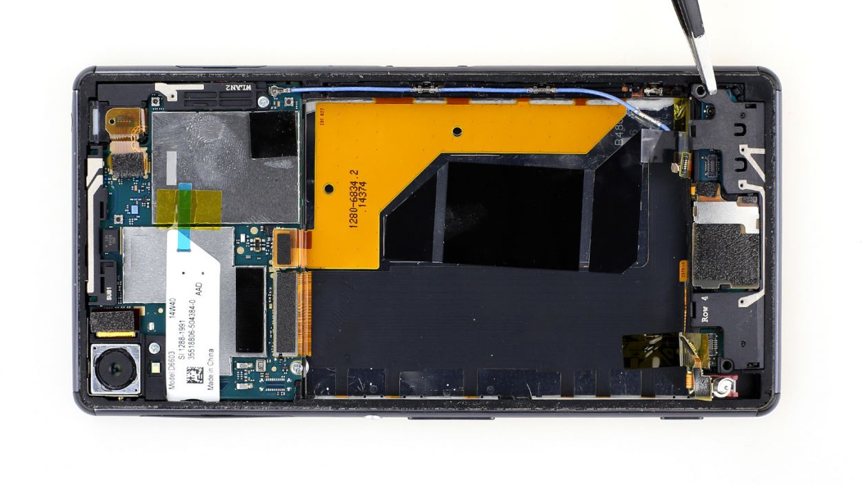
– Now, gently lift one side of the cover just a bit so you can get a good grip on it with your fingers.
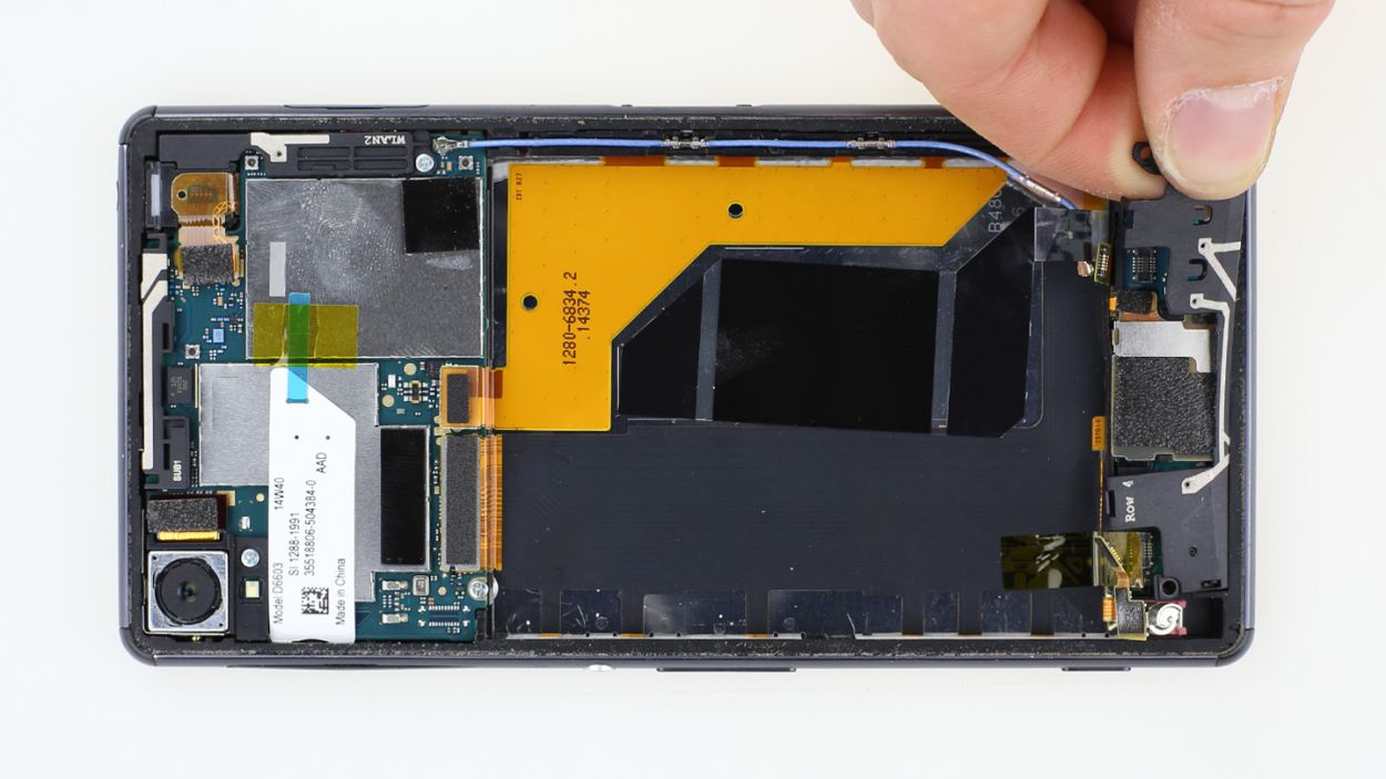
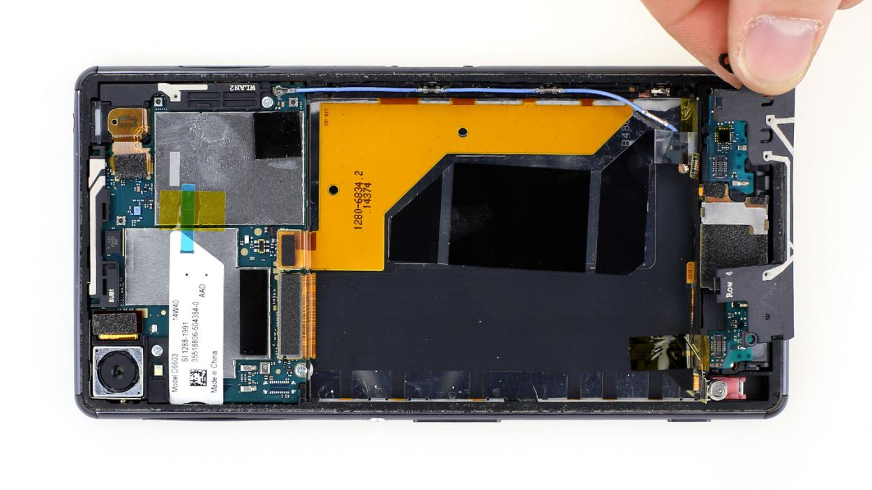
– With a little patience, pull the cover off slowly using your fingers until it’s completely free. You’ve got this!
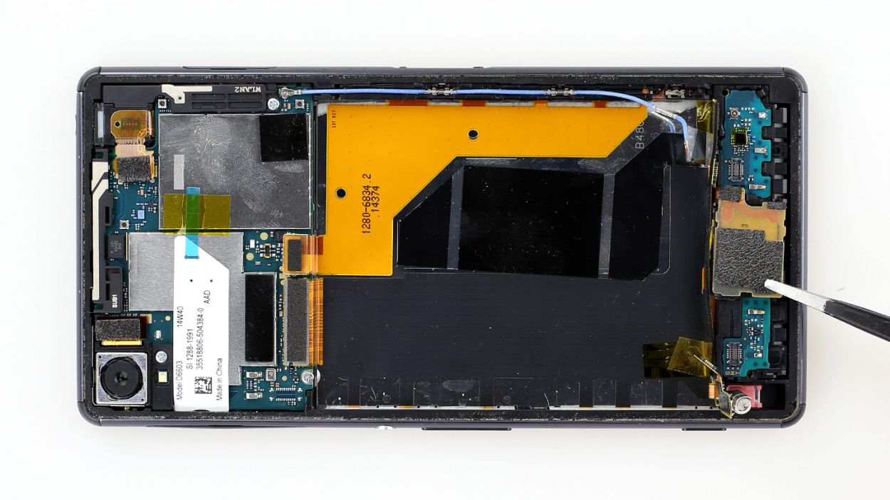
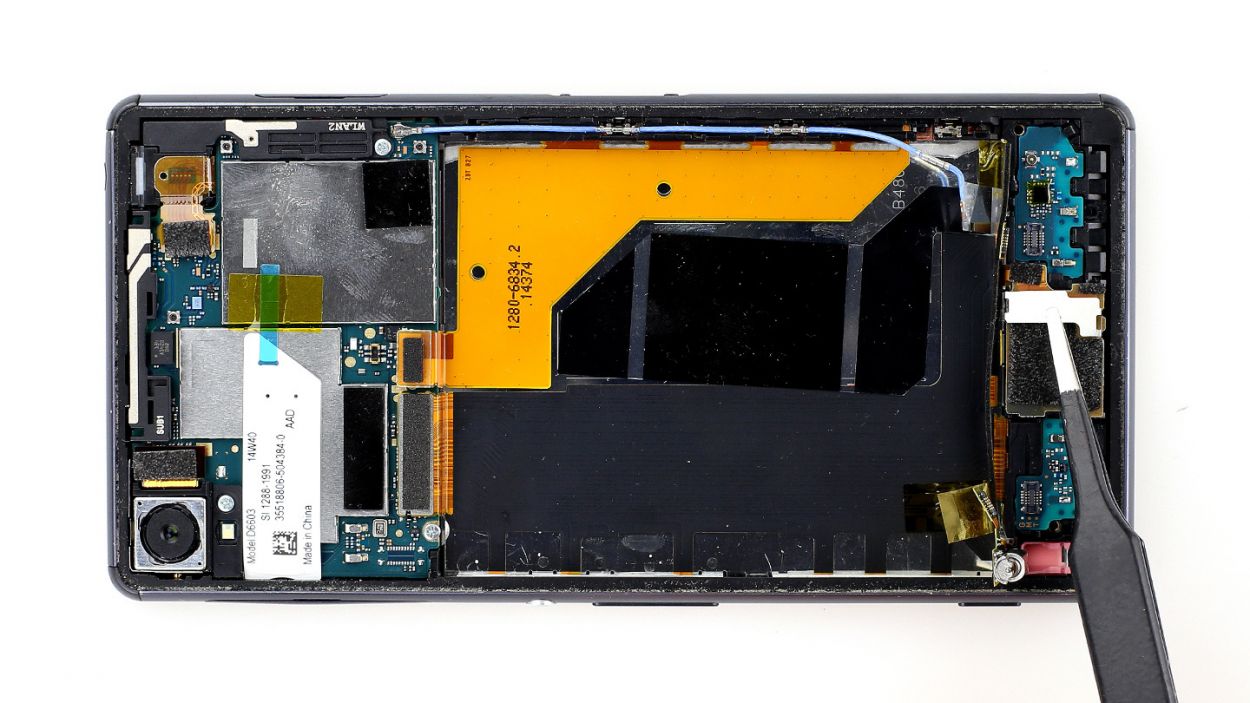
Step 6


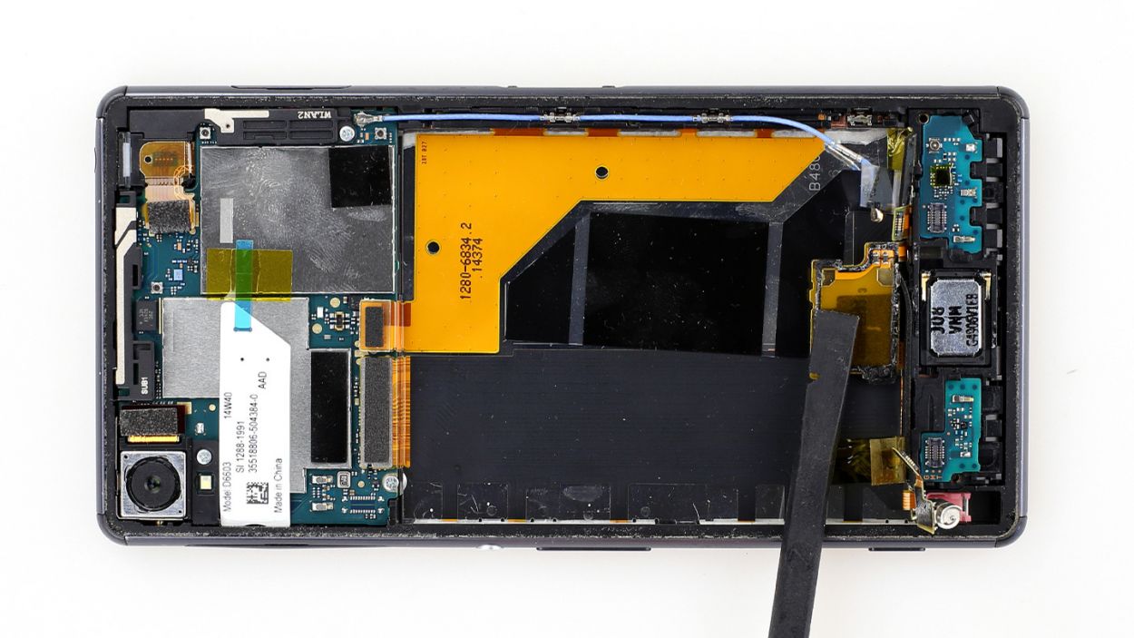
– First things first, let’s get that shiny silver cover off before we tackle the speaker’s contact area.
– It’s snugly held in place by the contact area, so grab your trusty laboratory spatula and gently pry it off to the side.
– Now, don’t forget that the contact area is also stuck to the plastic frame around the speaker. With the pointed tip of your spatula, carefully peel away that glued strip.
– Once you’ve freed the contact area, just fold it to the side and you’re all set!

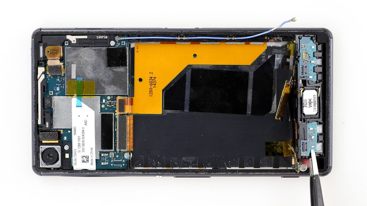
Step 8
– First things first, let’s peel off that copper foil so we can get to the speaker. It’s like unwrapping a present!
– Next up, grab your trusty spatula or spudger and gently slide it under the microphone, then give it a little fold to the side. Easy peasy!
– Now, let’s take off that shiny silver protective cover. It’s time to reveal what’s underneath!
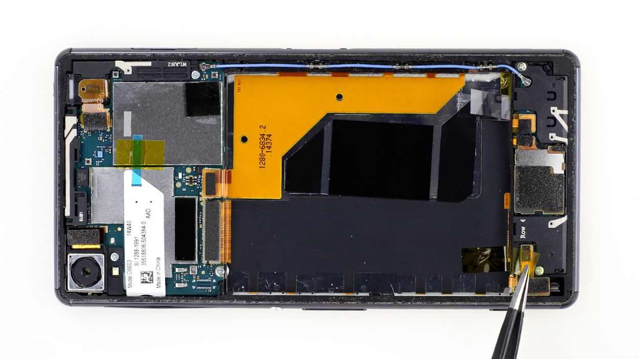
Step 9

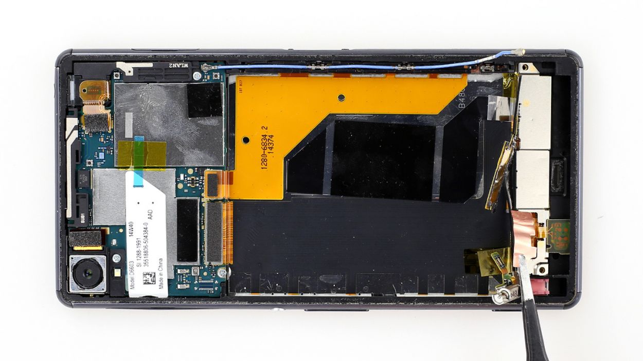
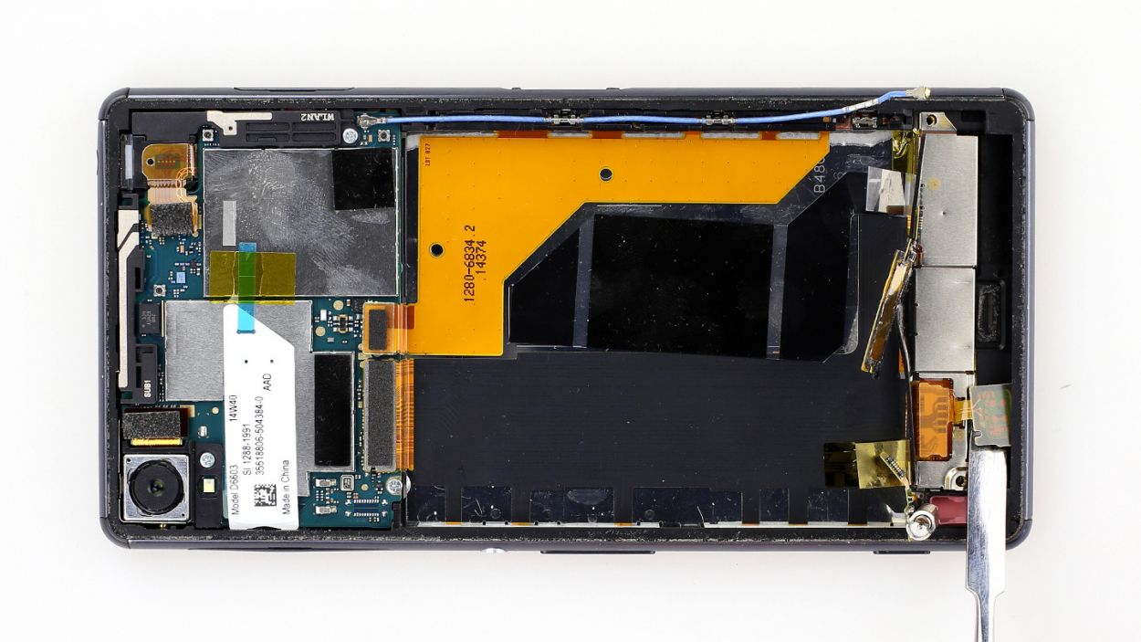
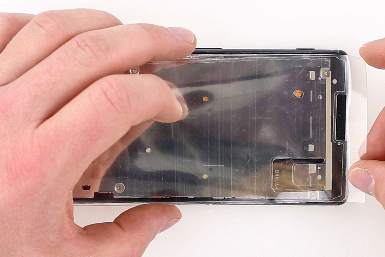
– Now disconnect the display cable. Insert the flat end of the spudger very slightly below the contact and lift it up. Make sure you don’t break off the resistors that are soldered on.
– Now remove the transparent protective film.
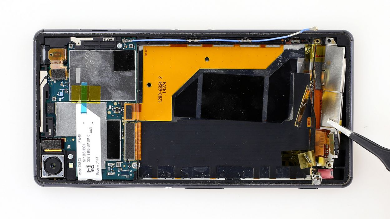
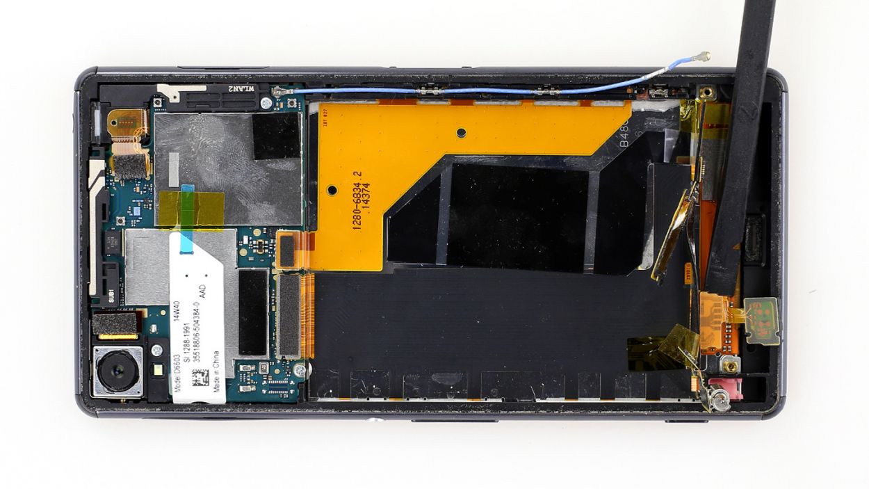
– Then lift the display’s connector board, which is glued firmly to the frame, by placing the flat end of the laboratory spatula below the connector board and carefully lifting it up. Use different positions.
– Tilt the board up as soon as it’s fully detached from the frame. It fits through the gap in the frame better this way.
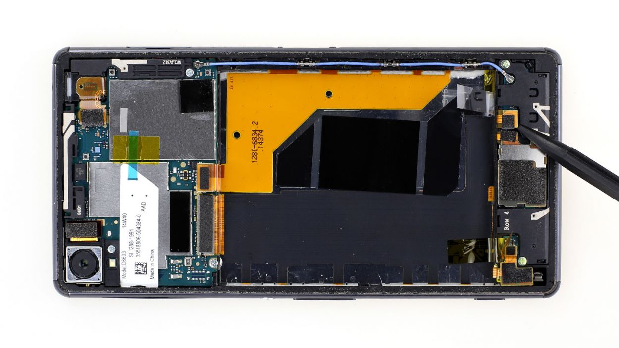
Step 10
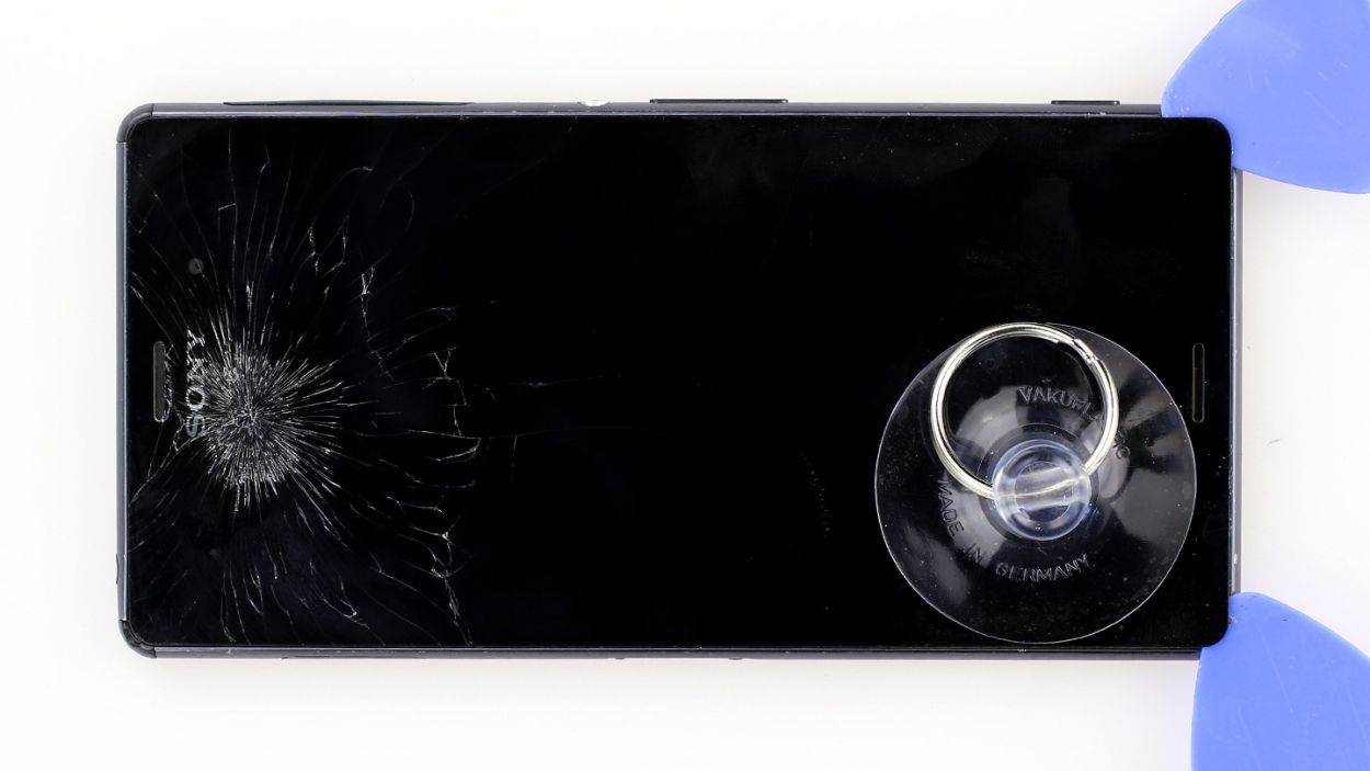
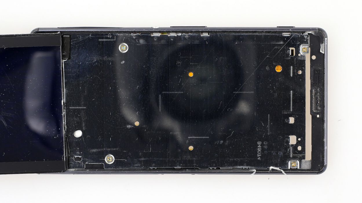
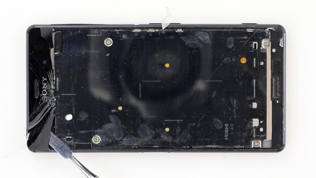
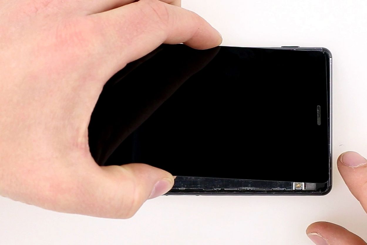
– Alright, let’s tackle that Sony Xperia Z3 display! It’s stuck on there pretty well, so grab your heat gun and give it a good warm-up to soften that stubborn glue. Once it’s nice and toasty, slide a plastic pick into the tiny gap between the frame and the display to break that adhesive seal.
– Now, here’s where the magic happens! Use a suction cup to gently pull on the display while you’re working it free. Just remember to guide the display’s connector board through the opening in the frame as you go.
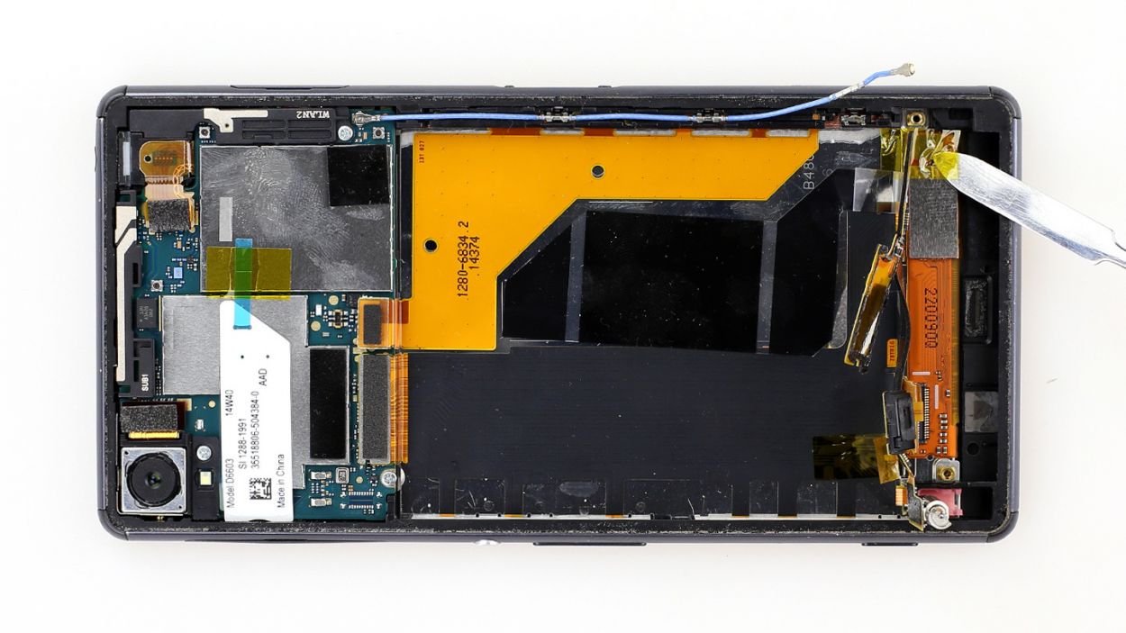
– Before you call it a day, make sure to clear out any old glass pieces from the frame. A clean workspace is a happy workspace!
Step 11
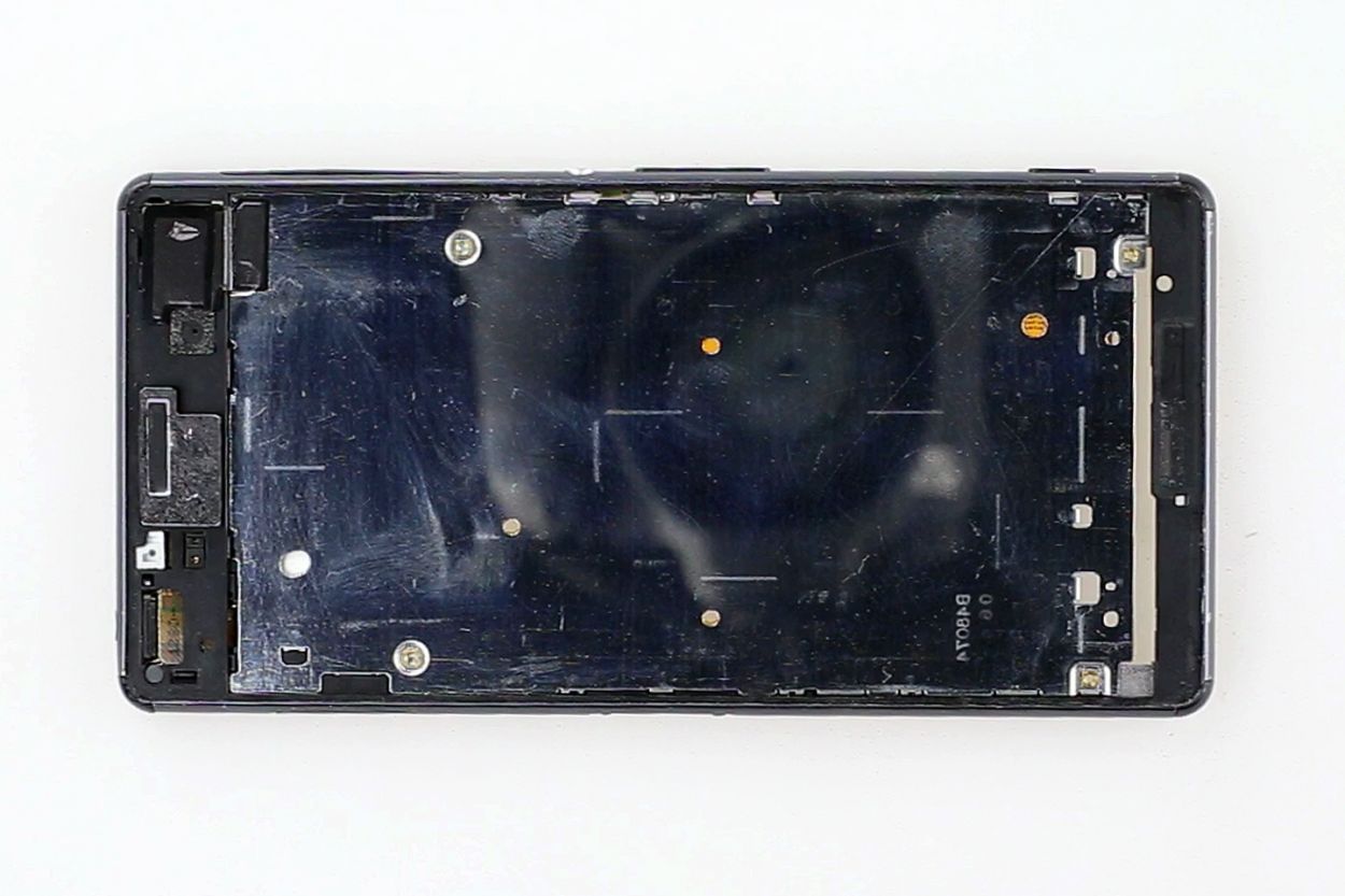
– Alright, let’s get this party started! Before you attach the new display, give the contact surfaces on the frame a good clean. We want to ensure a fabulous connection!
– Once they’re sparkling clean, it’s time to slap on that new adhesive film. Remember, a little funky fresh film goes a long way!
– Now, let’s make sure that speaker is fitting snug in its new home. We don’t want any sound waves getting lost in translation, do we?
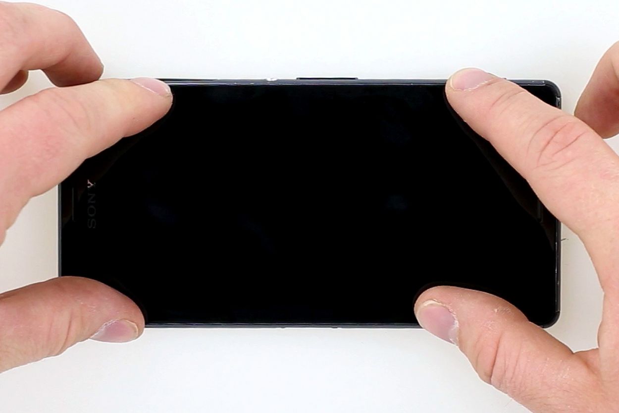
– Guide that new display’s connector board through the frame’s gap, place the display on top, and press it onto the frame for a bit. Just like making a new friend, it takes a little pressure to make it stick!
Step 12
– Gently fold the connector board back into place so it sticks snugly to the frame.
– Carefully reapply the transparent protective film right over the antenna cable.
Step 13

– Time to get your display connector board looking sharp again! Put that silver protective cover back where it belongs.
– Almost there! Reconnect the speaker display cable and slap that copper foil back on like a pro! If you need help, you can always schedule a repair.
Step 14

– Carefully place the sub-board back into its original position.
Step 15
– Gently fold the contact area back so it sits snugly against the top of the speaker again.
– Pop the silver cover back into place.
Step 16

– Time to pop that black plastic cover back on! Give it a good press to make sure it fits snugly into the frame.
– Now, grab those 2 x 3.3 mm Phillips screws and secure it all in place again. You’re doing great!
Step 17


– Alright, let’s get this show on the road! First up, attach the antenna cable, logic board connection, and vibration motor to the sub-board. It’s like playing with building blocks, but for your device!
– Next, slap that transparent protective film back on the vibration motor’s connector. Think of it as giving your device a high-five, but with a protective barrier!
Step 19
– Time to put the finishing touches on your repair!.
– So, the old adhesive is still sticky, right?
– Now, put the back cover back on, give it a gentle warmth with a hair dryer (careful, don’t burn yourself!) and press it firmly onto your device for a bit. Easy peasy!
