DIY Guide to Replace Taptic Engine in iPhone SE 2020
Duration: 45 minutes
Steps: 32 Steps
Pssst! Just a heads up…
The Taptic Engine is what makes your iPhone buzz and gives it that delightful haptic feedback. This guide will walk you through the steps to remove or replace the Taptic Engine in your iPhone SE 2020. Just a heads up: we’ll be fully detaching the display assembly to make things easier and to keep those delicate display cables safe from any mishaps. If you’re feeling confident and want to keep the display cables connected while you tackle the Taptic Engine, feel free to skip the steps for disconnecting the display. If you need help, you can always schedule a repair.
Step 1

Hey there, before diving in, make sure your iPhone’s battery is below 25%. A fully charged lithium-ion battery can be a bit of a firecracker if it gets punctured!
Don’t forget to power down your iPhone before you start taking things apart. Safety first, right?
Hey there tech wizard! Before you dive into opening the iPhone’s display, remember that its waterproof seals are your device’s BFFs! Grab some replacement seals so they can keep on being the superheroes they are. Ready to make your iPhone superhero-proof again? Let’s do this!
– Unscrew the two 3.5 mm pentalobe screws hanging out on the bottom edge of your iPhone.
Step 2


Don’t go too deep with that opening pick! To keep things safe, follow this step and mark your pick. If you need help, you can always schedule a repair.
– Grab your opening pick and measure about 3 mm from the tip, then mark that spot with a permanent marker. This little mark will help guide you, so you don’t miss the sweet spot!
Step 3


In the next three steps, we’ll show you how to use the Anti-Clamp, our nifty little tool designed to make opening your device a breeze. If you’re not rocking the Anti-Clamp, no worries! Just skip ahead three steps for a different approach.
– Give that blue handle a gentle tug back to liberate the Anti-Clamp’s arms.
– Glide those arms over the left or right border of your trusty iPhone.
– Place those suction cups close to the lower edge of the iPhone right above the home button—one in the front, the other in the back.
– Press those cups together to create some suction magic on the desired spot.
Step 4


– Give that blue handle a gentle tug forward to lock those arms in place.
– Now, twist the handle a full 360 degrees or until you see those suction cups start to stretch out a bit.
– Keep an eye on those suction cups to make sure they’re staying in sync. If they start to drift apart, just loosen them up a tad and realign those arms.
Step 5


– Heat up an iOpener and slide it through the arms of the Anti-Clamp.
– Fold the iOpener so it rests along the bottom edge of your iPhone.
– Give it about a minute to let the adhesive loosen up and create a small gap.
– Carefully insert an opening pick into the gap.
– Skip the next three steps.
Tools Used

Step 6

Get ready to tackle the next three steps where we’ll show you how to gently pop that screen off using a trusty suction cup. Let’s do this!
– Warming up the bottom edge of your iPhone will make peeling off the adhesive a breeze, making it super easy to open up.
– Grab a hairdryer or prep an iOpener and heat up the bottom edge of your phone for around 90 seconds. This will loosen up that pesky adhesive underneath.
Tools Used
Step 7


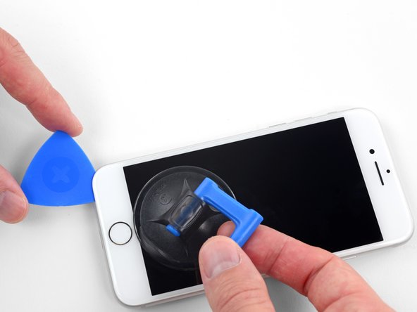
– Grab a suction cup and stick it to the lower part of the front panel, right above the home button. Let’s get that panel off with style!
Step 8


The adhesive keeping the screen sealed tight is pretty tough, so you’ll need to put in some elbow grease to create that first gap. If you’re struggling to get it started, try applying a bit more heat and gently wiggling the screen up and down. This will help loosen the adhesive until you can slide your tool in and get things moving.
– Gently coax the suction cup upward with a steady, unwavering force to initiate a small gap between the screen and the frame.
– Slide an opening pick into the gap.
Step 9


Don’t even think about prying the top edge of the display from the rear case—those plastic clips are like loyal little guardians and might snap! If you need help, you can always schedule a repair
– Gently glide the opening pick along the left side of the phone, starting at the bottom and making your way up towards the volume buttons and silent switch. This helps loosen up the grip of the adhesive that’s keeping the display in place.
– Pause when you reach the top left corner of the screen.
Step 10

Watch out for the delicate cables on the right side of your iPhone. Keep your pick away from here to avoid causing any damage. If you need help, you can always schedule a repair.
Step 11


– Pop your tool back into the lower right corner of the iPhone, then gently glide it around the corner and up the right side to break that adhesive seal. You’ve got this!
Step 12


– Carefully pull up on the suction cup to lift the bottom edge of the display. Take it slow – no need to rush!
– Once you’ve got that edge up, give the small nub on the suction cup a gentle tug to remove it from the front panel.
Step 13


– Slip an opening pick under the display at the top left corner and glide it along the top edge to lift up the last bit of adhesive.
Step 14


– Gently slide the display assembly downward (away from the top edge of the phone) to pop off the clips securing it to the rear case. If you need help, you can always schedule a repair.


Step 16

– Unscrew the four Phillips screws that are holding the lower display cable bracket in place on the logic board. These screws come in different lengths, so keep track of which one goes where.
– Pro tip: As you go through this guide, make sure to keep your screws organized. Putting a screw in the wrong spot can cause some serious damage, so it’s worth taking a moment to stay organized.
– Carefully lift off the bracket.
Step 17

– Grab your trusty spudger and gently nudge the battery connector out of its cozy spot on the logic board.
– Give that battery connector cable a little bend away from the logic board. This way, it won’t accidentally touch the socket and power up the phone while you’re in the zone repairing.
Tools Used

Step 18


– Hey there, it’s time to use the point of a spudger to gently pry out the lower display connector from its slot.
– To reunite press connectors, gently press one side until you hear a satisfying click, then repeat on the other side. Avoid pressing down on the middle as that could lead to a wonky connection. Remember, a slight misalignment can cause trouble, so let’s avoid that!
Tools Used


Step 20


– Time to bid farewell to those three 1.3 mm Phillips screws that have been holding the front panel sensor assembly connector bracket hostage. Show them the way out!
– With grace and finesse, relieve the bracket of its duties. It’s time for a new chapter.


Step 23

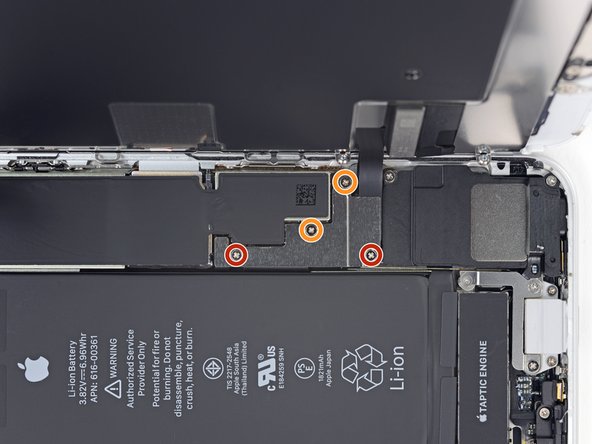
– Let’s get started by taking out the three screws that are holding the bracket next to the Taptic Engine in place:
– One 1.3 mm Y000 screw – it’s a tiny guy, but it plays a big role!
– One 2.7 mm Phillips screw – just the right size for a secure connection.
– One 2.9 mm Phillips screw – a little longer, but still easy-peasy!
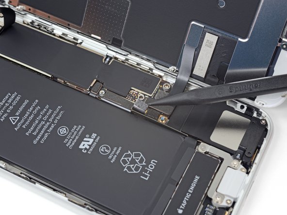
Step 24

– Time to say goodbye to that bracket! Just give it a gentle nudge and remove it.
Step 25


– Carefully slide an opening pick in between the antenna flex cable and the top of the speaker. You’ve got this!
Step 26


– Grab your trusty spudger and gently nudge it under the diversity antenna flex cable to lift it up and disconnect it from the logic board. You’ve got this!
Tools Used
Step 27


– Gently slide an opening pick under the antenna flex cable to keep that socket in place.
– Now, grab your trusty spudger and use its pointy end to carefully pry up and disconnect the antenna flex cable from its socket, while the opening pick holds the socket steady.
Tools Used
Step 28

– Go ahead and take out the Wi-Fi diversity antenna. You’ve got this!
Step 29

– Time to unleash your inner handyman! Let’s tackle those two screws holding the Taptic Engine in place:


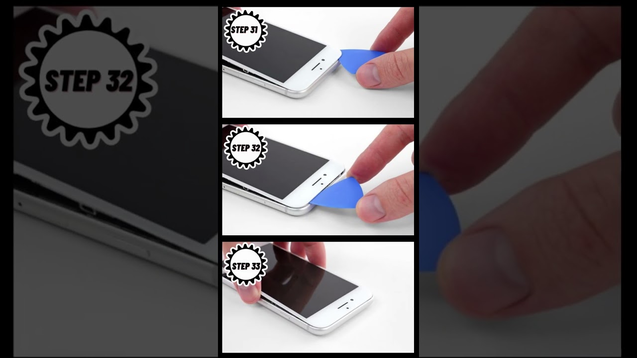
Step 31


– Gently use your spudger to pop up and unplug the Taptic Engine flex cable. If you need help, you can always schedule a repair.
Tools Used
Step 32

Take it easy when you’re removing the Taptic Engine flex cable; it might be sticking to the antenna flex cable like they’re best buds!
– Time to say goodbye to the Taptic Engine! Gently remove it and keep moving forward with your repair journey. You’ve got this!