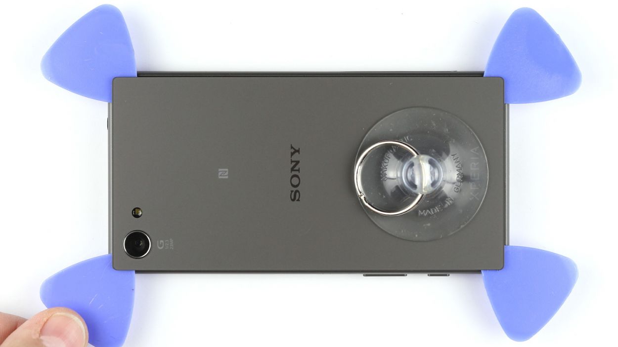
DIY Guide to Replace the Standby Volume Control Cable for Sony Xperia Z5 Compact
Duration: 45 min.
Steps: 28 Steps
Ready to bring your Sony Xperia Z5 Compact back to life? In this guide, we’ll walk you through the steps to replace that pesky standby/camera shutter release/ambient microphone cable that’s been causing you trouble. If your standby button, shutter release, or volume rocker switch has thrown in the towel, or if your ambient microphone, fingerprint sensor, or vibrator motor are acting up, it’s time for a swap! Let’s get this repair done together. Remember, if you need help, you can always schedule a repair.
Step 1

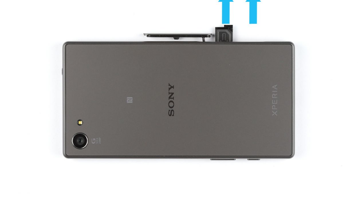
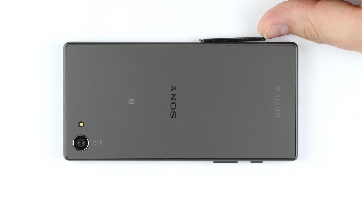
– Get ready to dive in! Use your finger or a spudger to gently pry open the cover at the lower end of your smartphone. Give it a little twist, about 90°, to make accessing that card slot a breeze!
– Now, let’s free those cards! Carefully remove the SIM and microSD cards—your SIM card will be snug in its tray.
Step 2

The back cover is spiffed up with a chic paint job on the inside! Just be sure to gently tackle any sticky residue so you keep it looking sharp and crack-free.
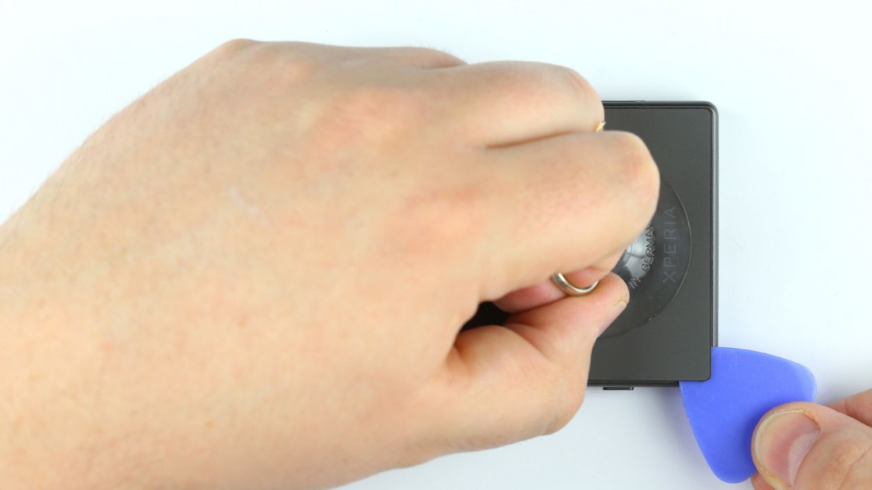
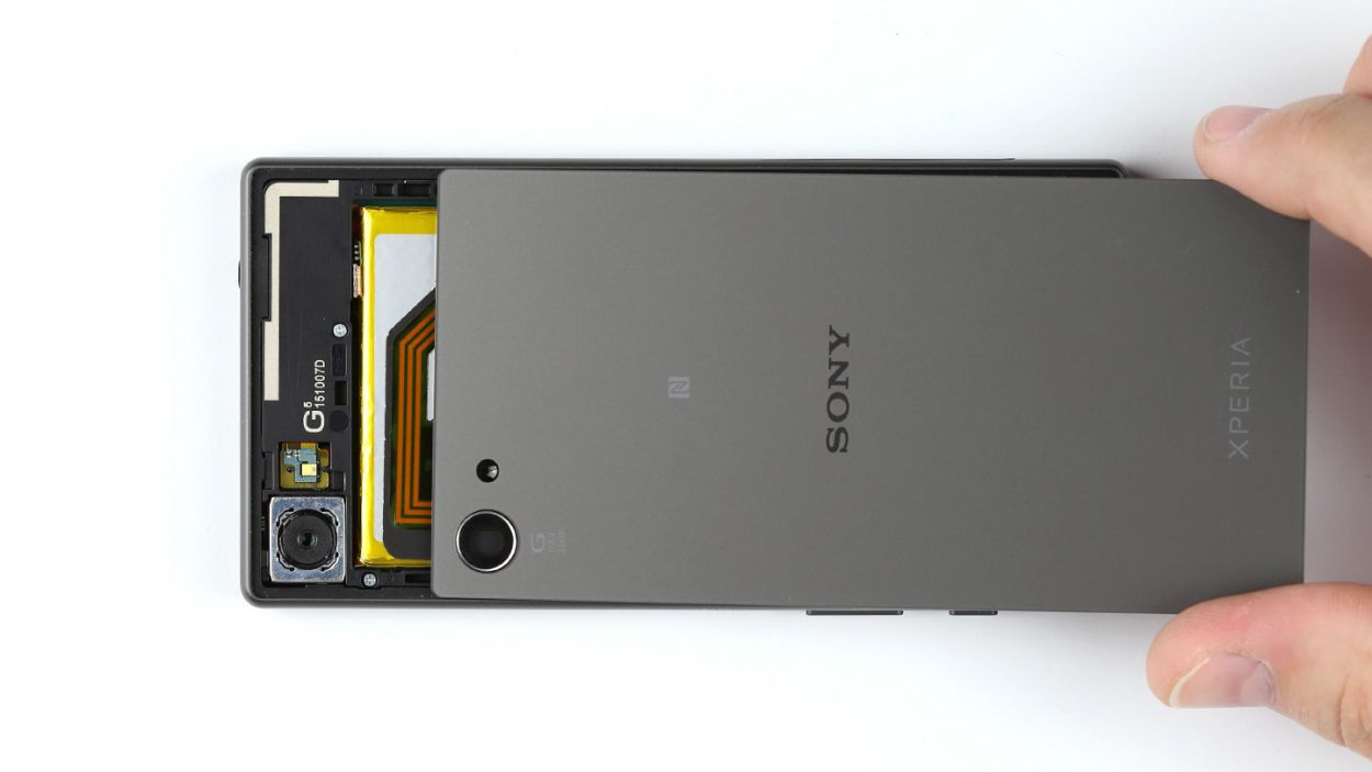
– That stubborn back cover’s glued on tight! Let’s loosen its grip with a little heat from a heat gun. Easy peasy!
– Grab a suction cup and stick it to the bottom. Now, gently pull while easing a plastic pick underneath the chassis. We’re creating a tiny gap!
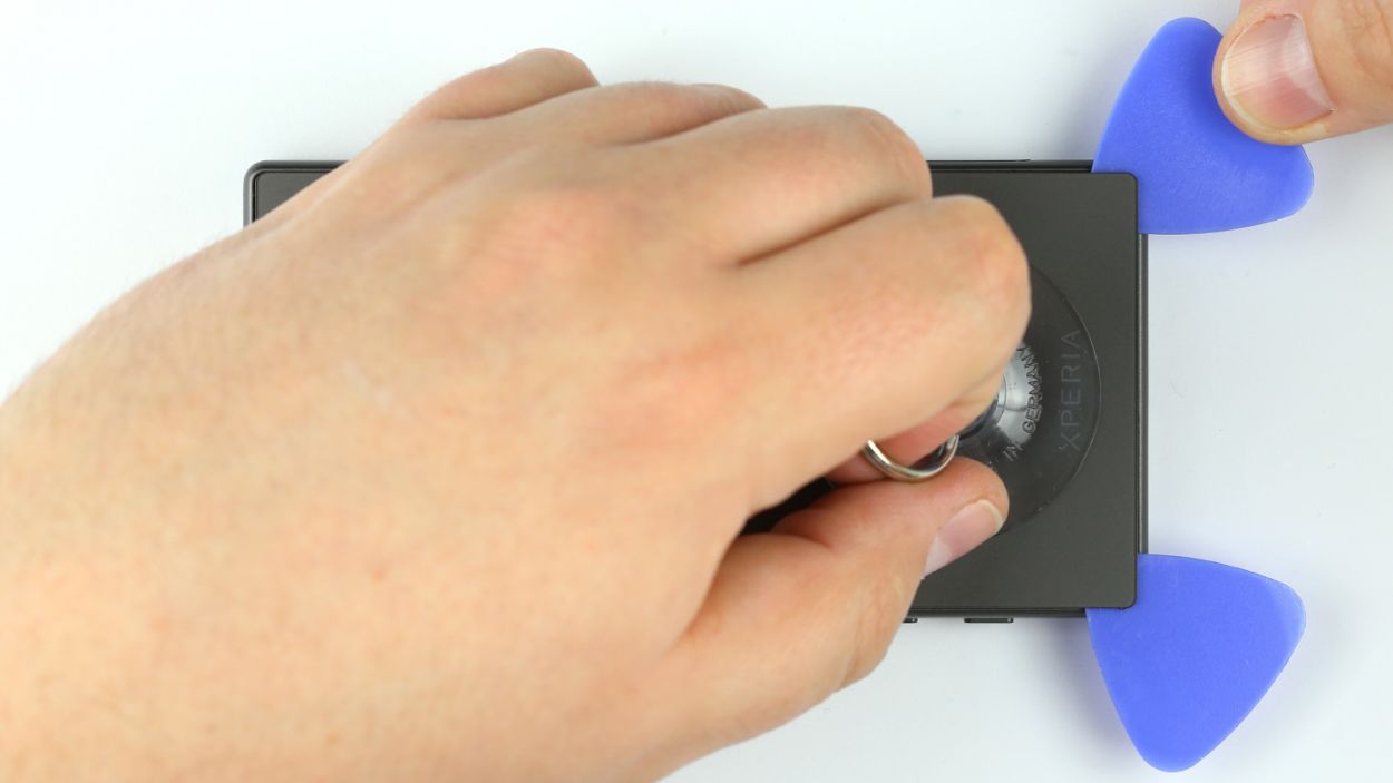
– Once you see that gap, slide the pick in. (The back cover’s painted inside, so be gentle to avoid any oopsies!) Carefully remove any sticky residue.
– Time to wiggle that pick around the whole device, freeing the glue. If you have extra picks, use ’em! Teamwork makes the dream work.
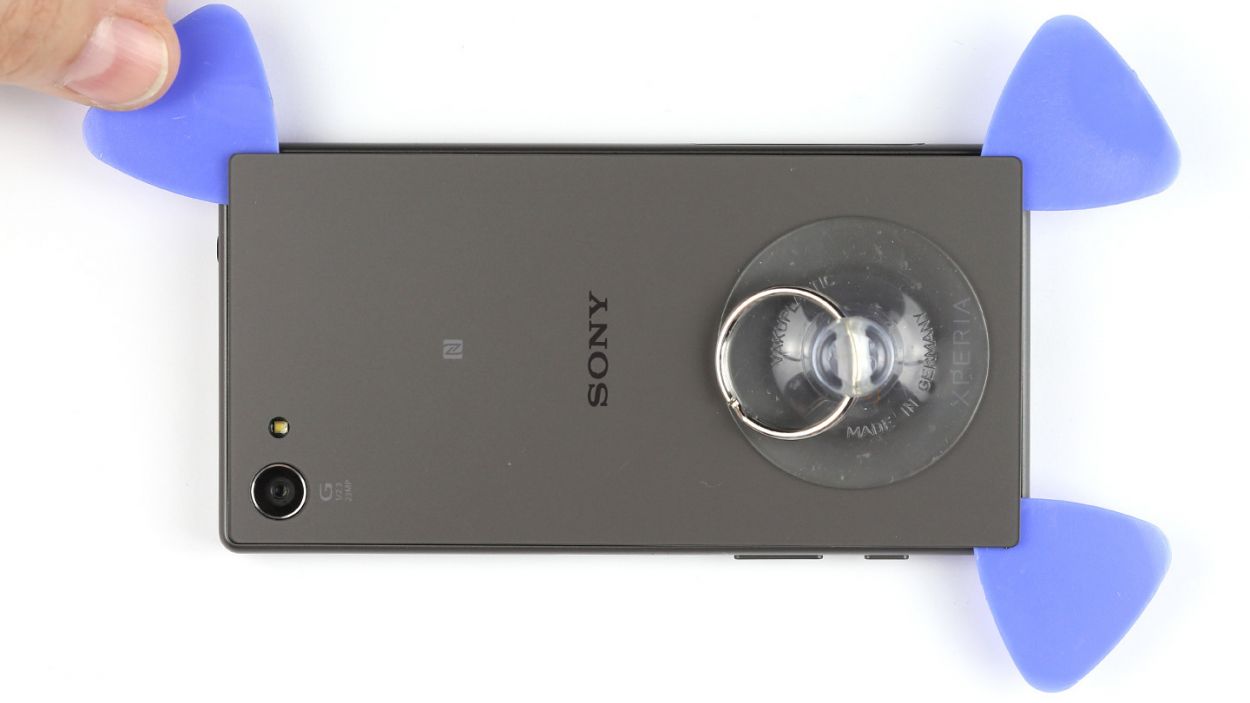
– And there you have it! The back cover is free. High five!
Step 3

– Pop off the type plate! It’s snugly tucked away in the SIM and microSD card slot, just waiting for you to give it a little nudge.
Step 4
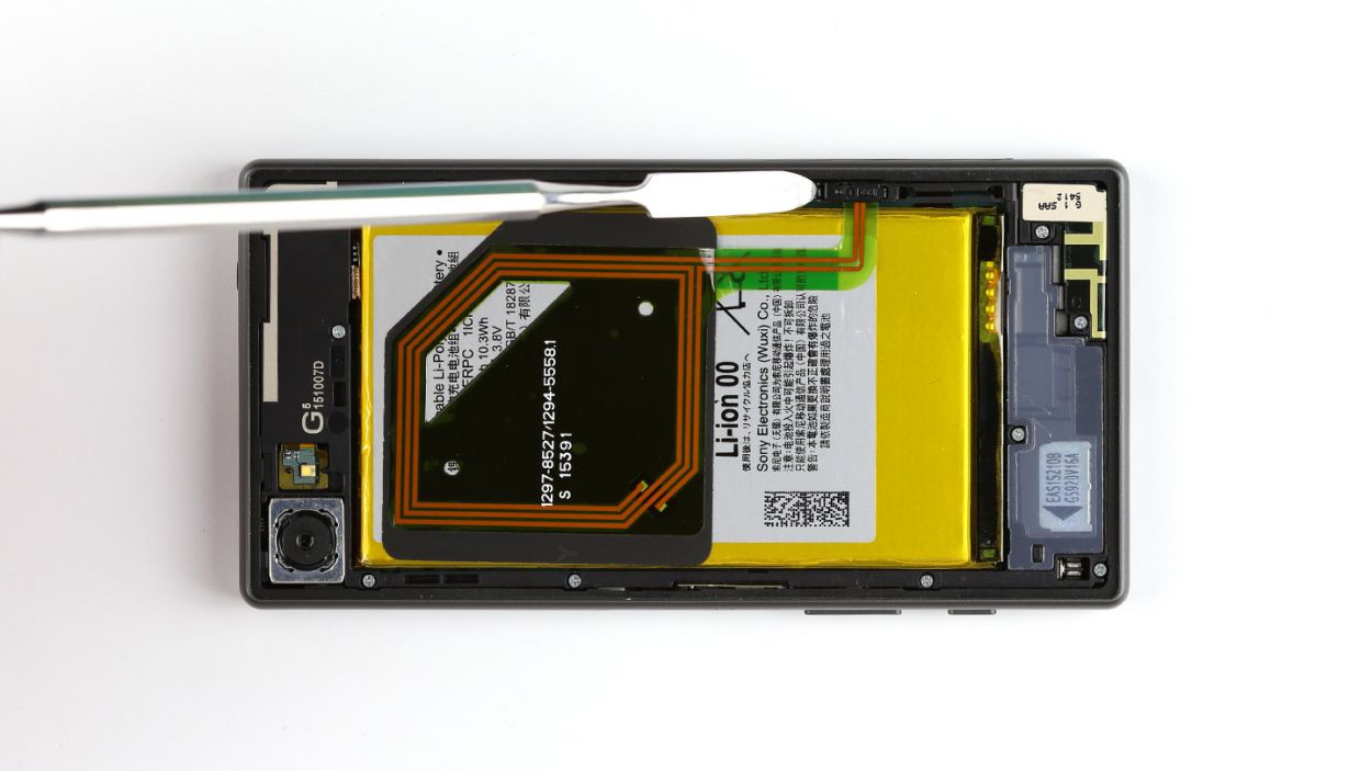
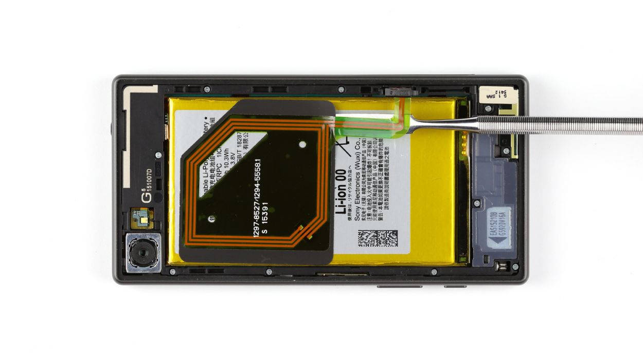
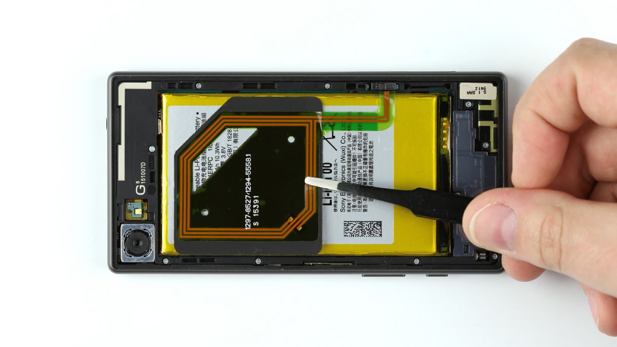
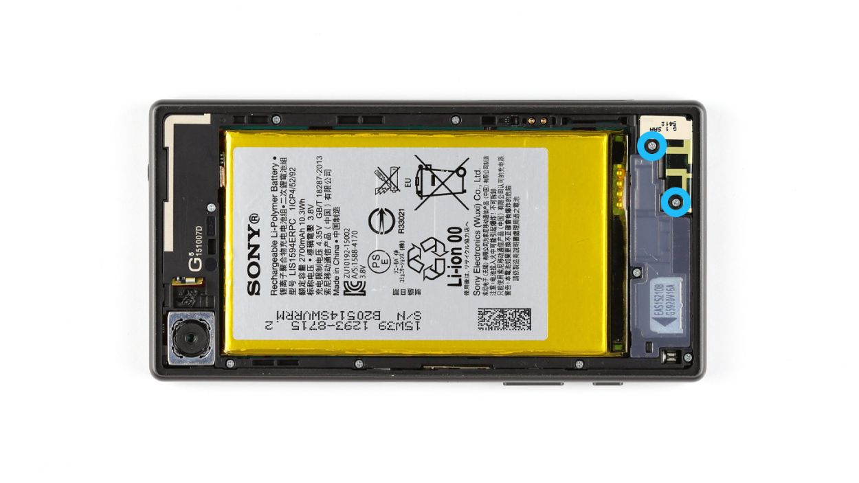
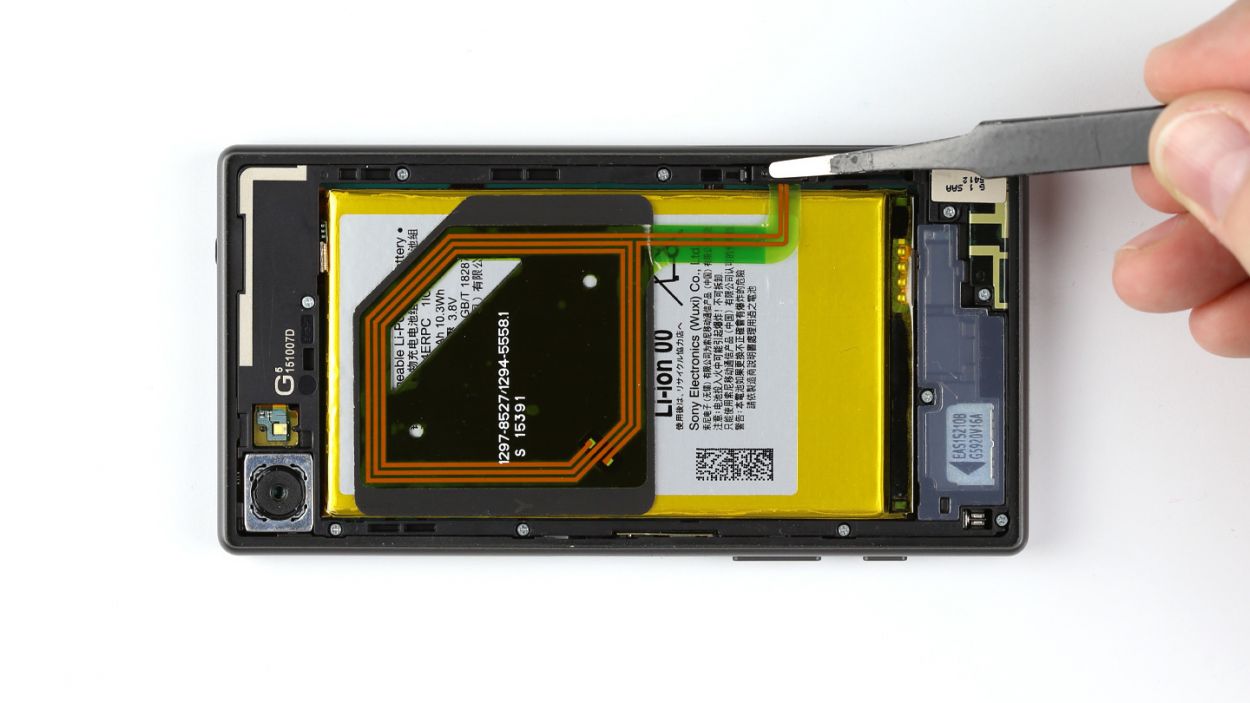
– First things first, gently unplug the NFC antenna’s connector from the chassis. Easy peasy!
– Next up, let’s disconnect the antenna from the battery. It’s stuck on there pretty good, so grab a steel laboratory spatula and carefully slide it between the antenna and the battery. If the glue is being stubborn, a little heat on the NFC antenna should do the trick.
– Now, it’s time to remove the NFC antenna. You’ve got this!
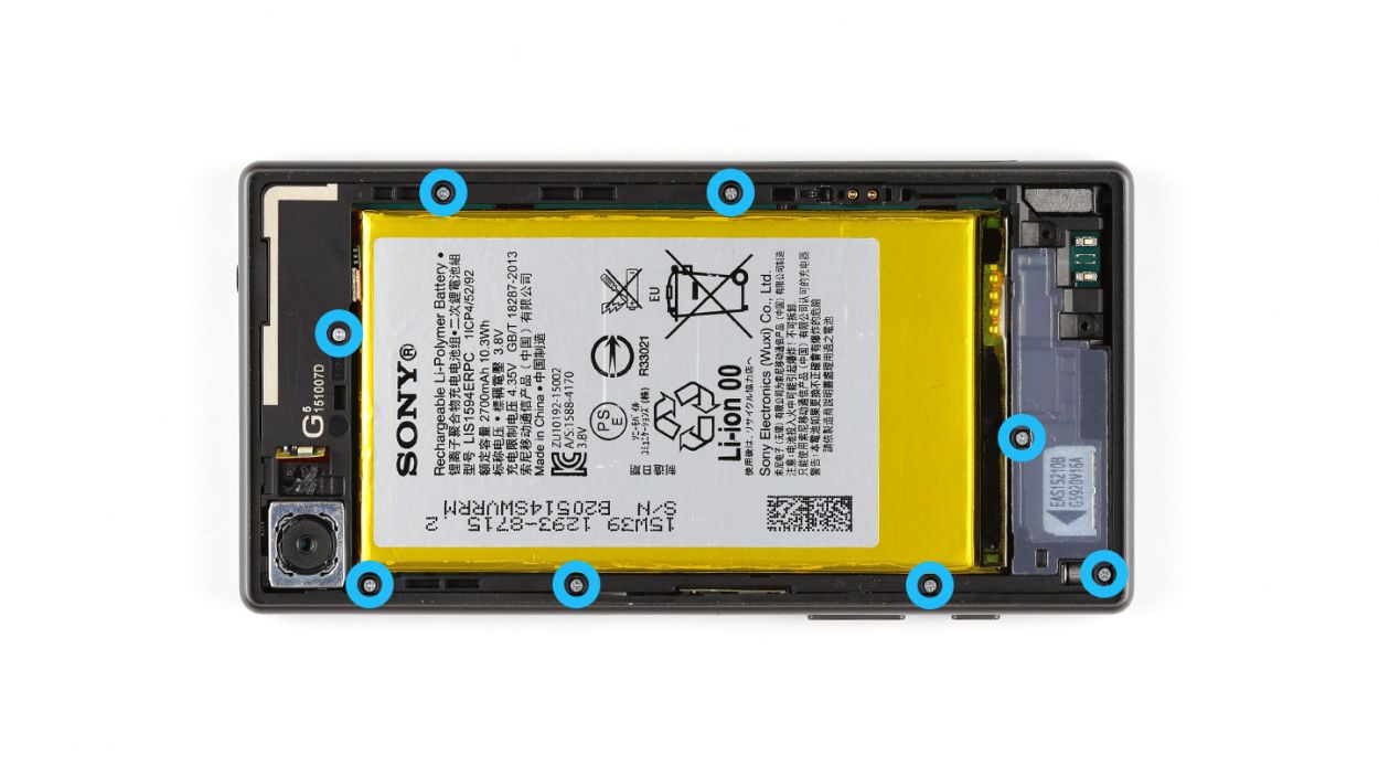
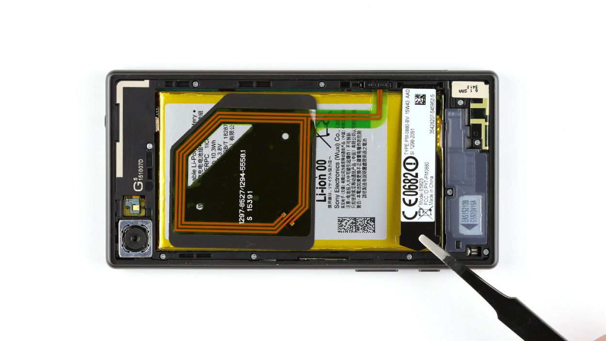
Step 5

– Grab your trusty Phillips screwdriver and unscrew those two 4.5 mm screws that are keeping the main antenna snug as a bug. You’ve got this!
– Once those screws are out, gently lift the main antenna away from the device. Easy peasy!
Step 6


– Grab your trusty steel laboratory spatula and gently pry the LED flash away from the chassis. It’s got a little glue holding it in place, but you’ve got this!
– Next up, let’s tackle those eight Phillips screws that are keeping the chassis snug against the display. They’re the 8 x 4.5 mm kind, so make sure you’re ready to unscrew them!
– Now, the chassis is a bit attached to the display, so use your steel spatula to help separate them. Just slide it in between the chassis and the display and give it a gentle nudge.
– Finally, carefully lift off the chassis. You’re almost there!
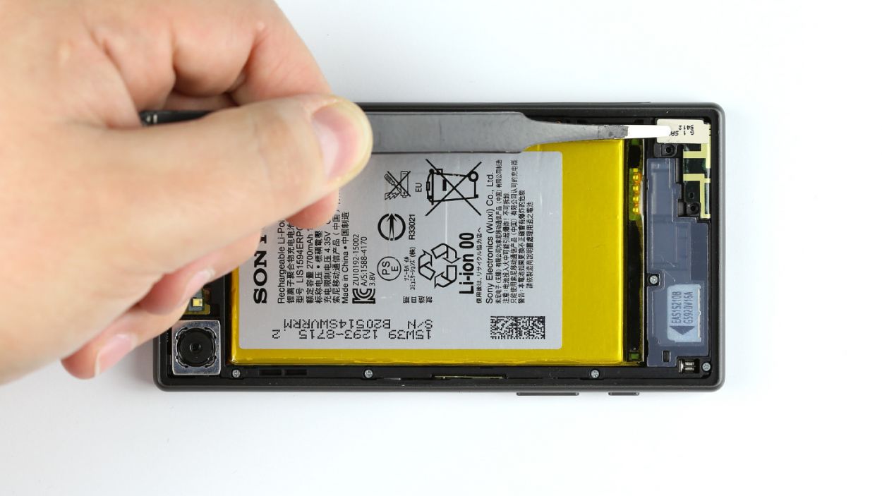
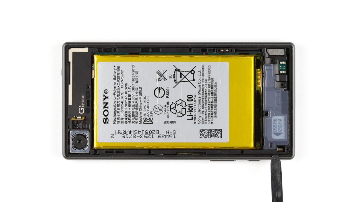
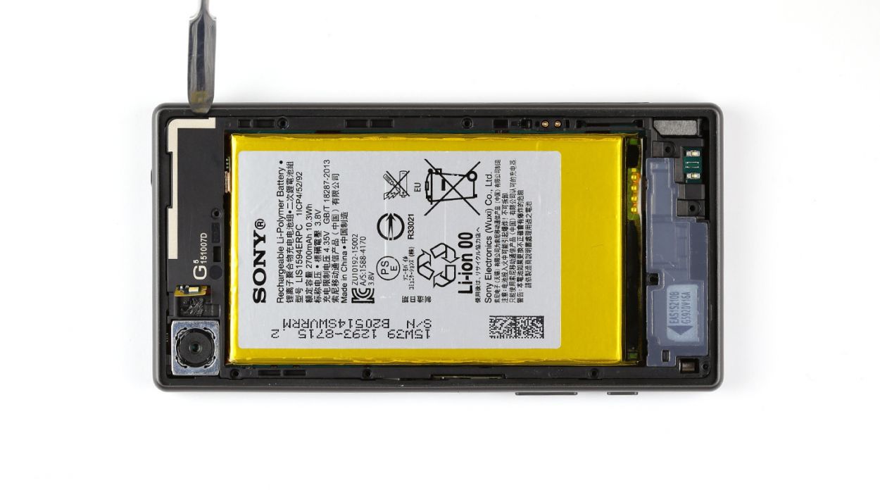
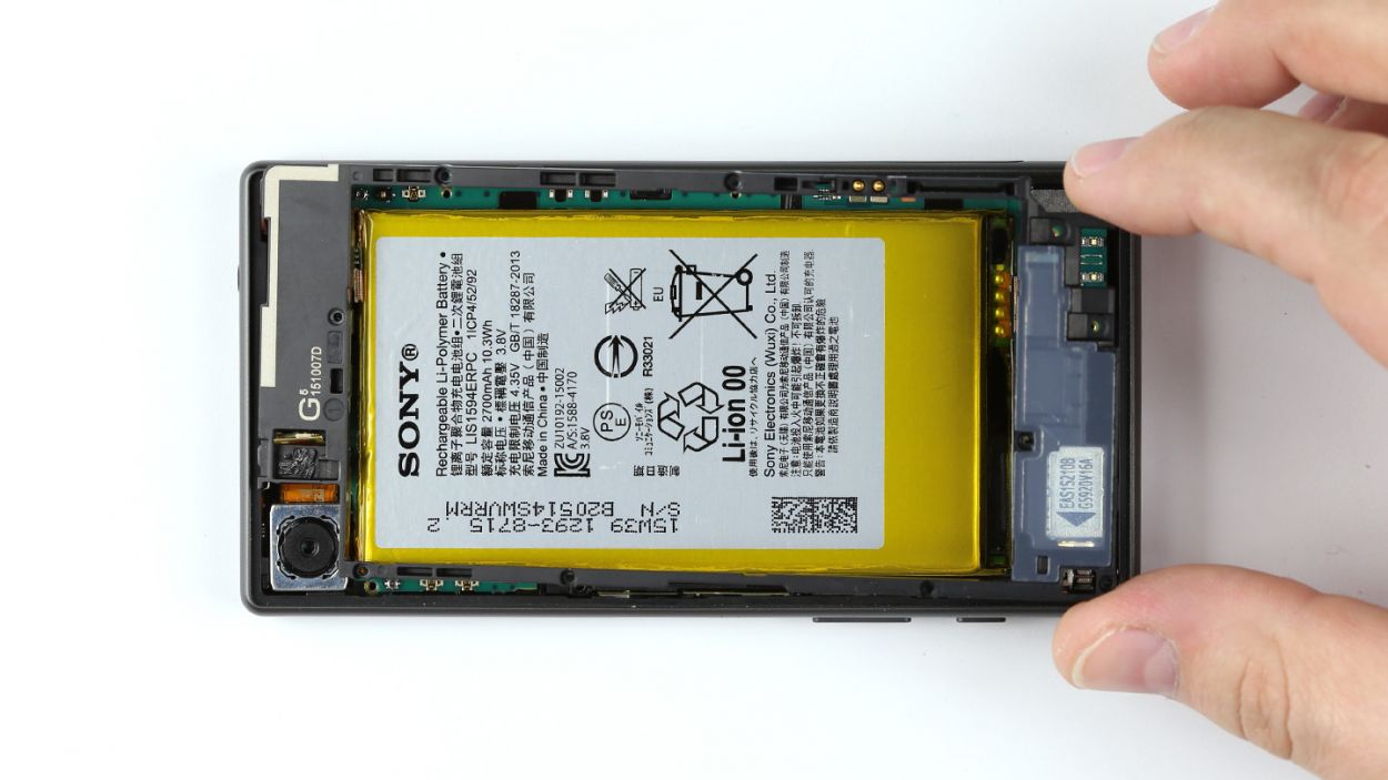
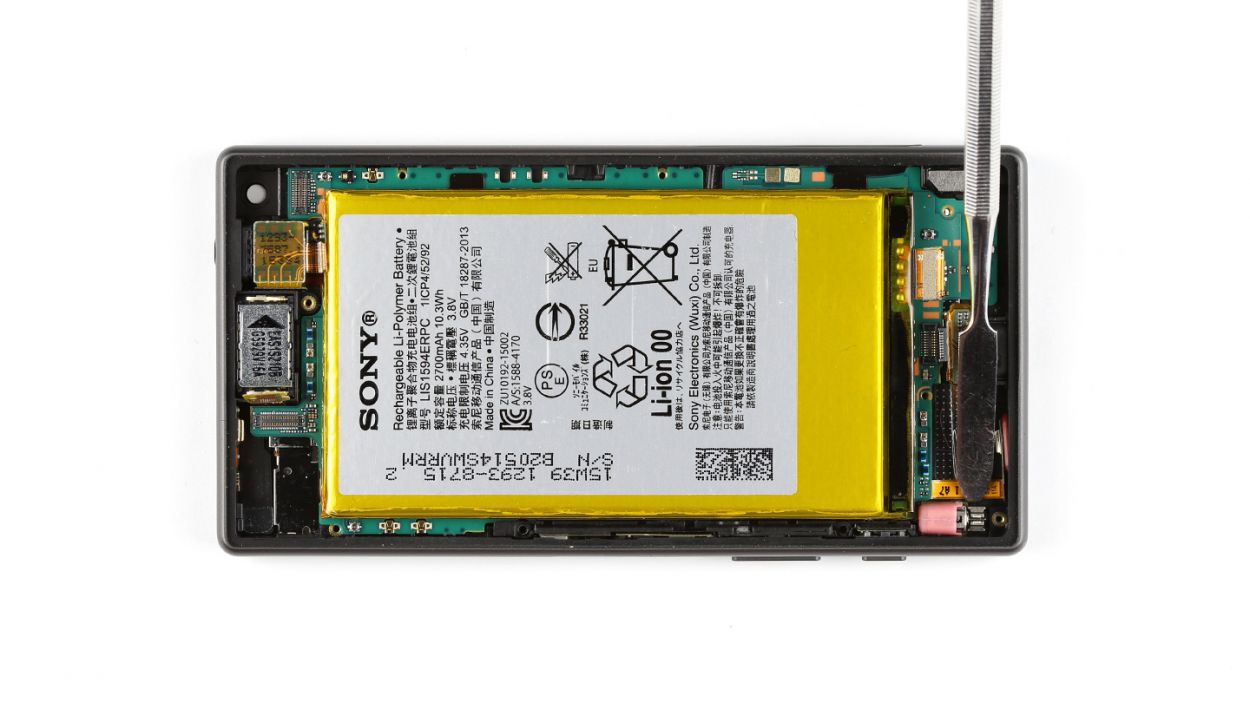
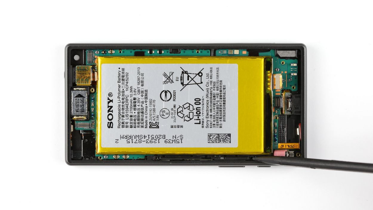
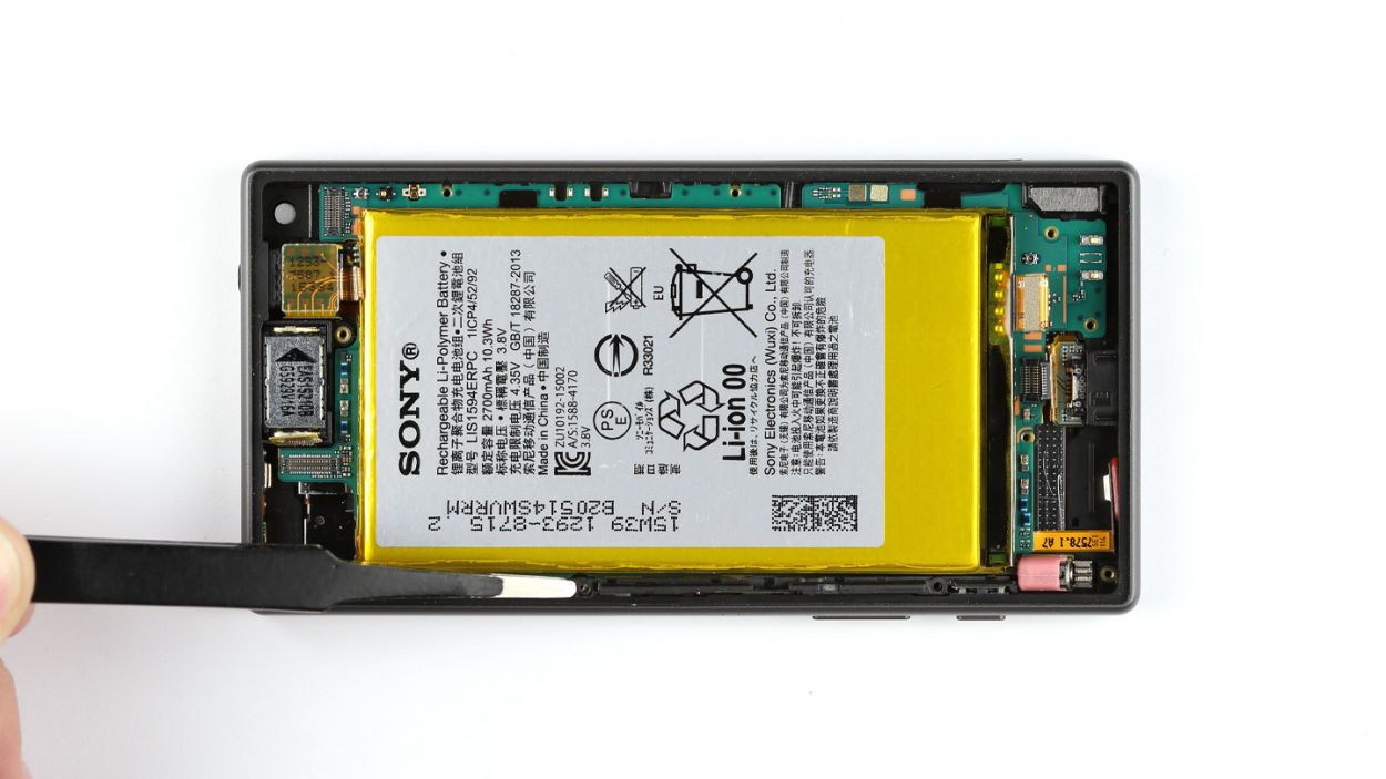
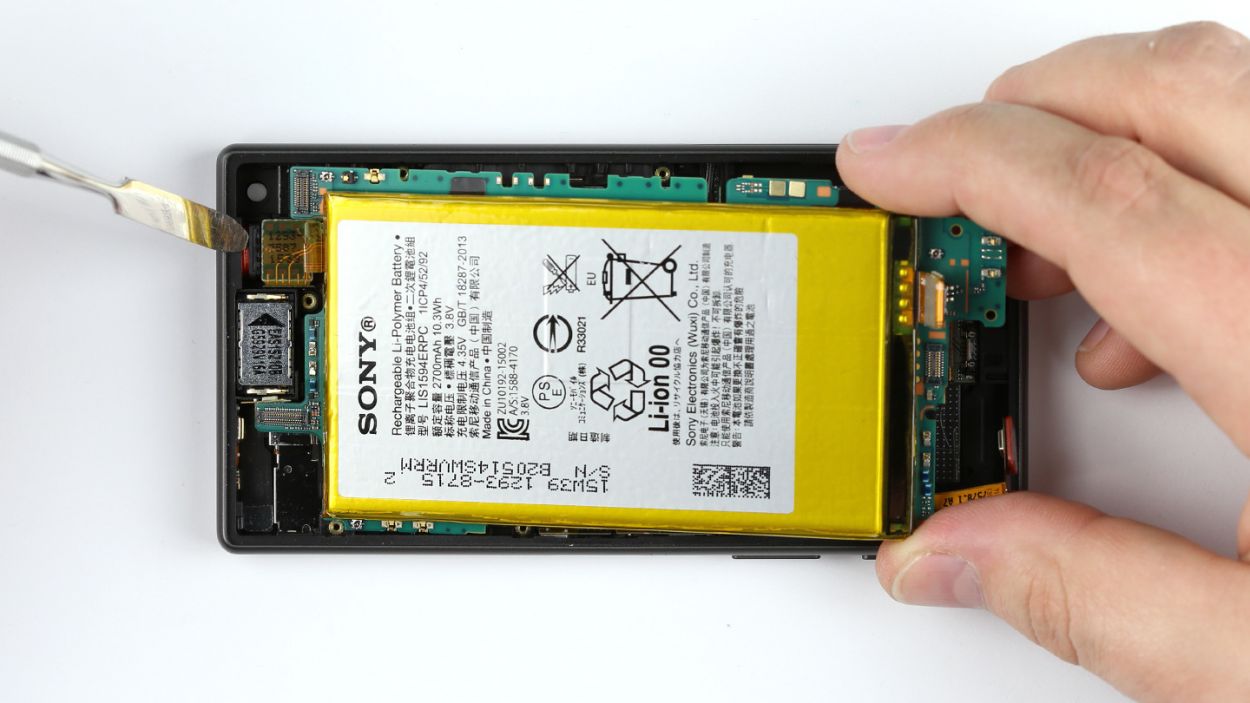
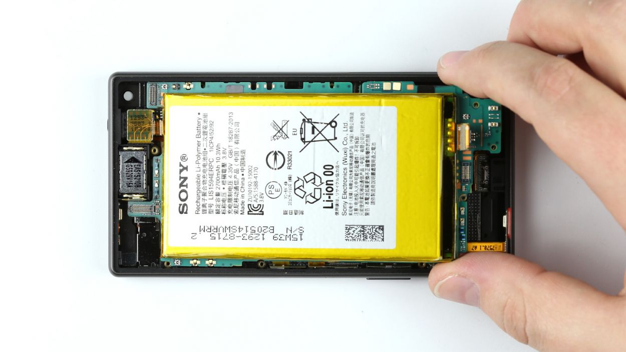
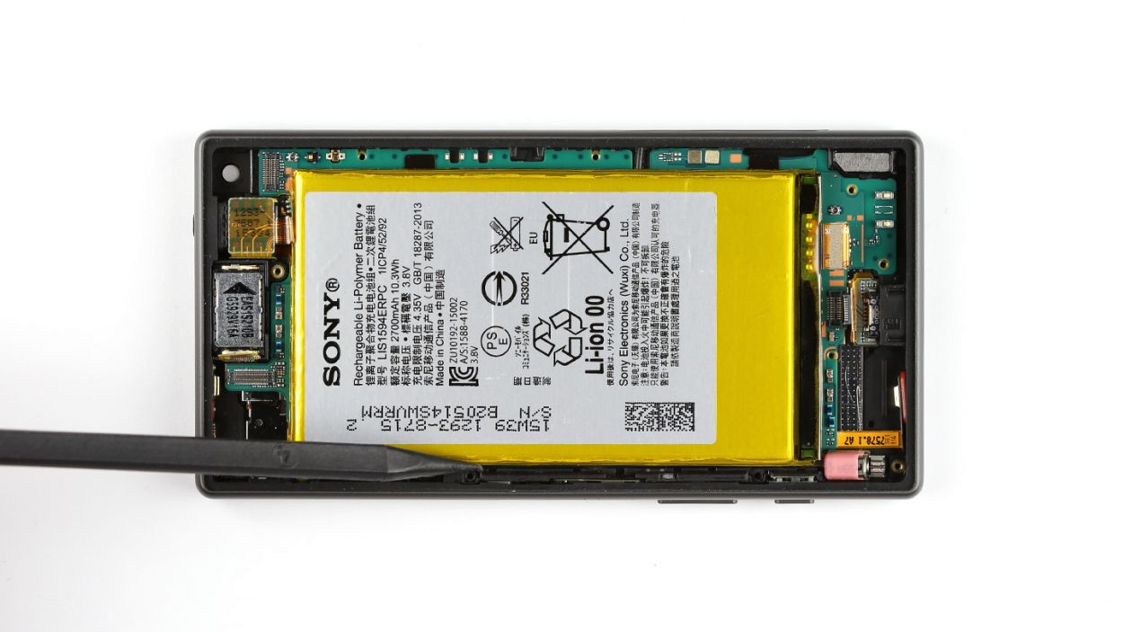
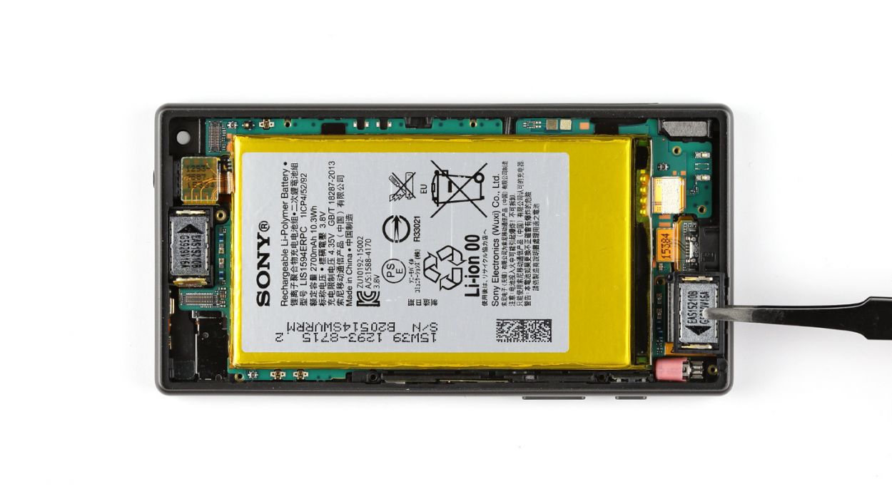
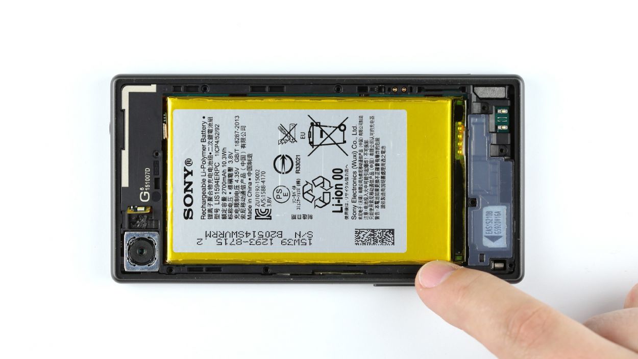
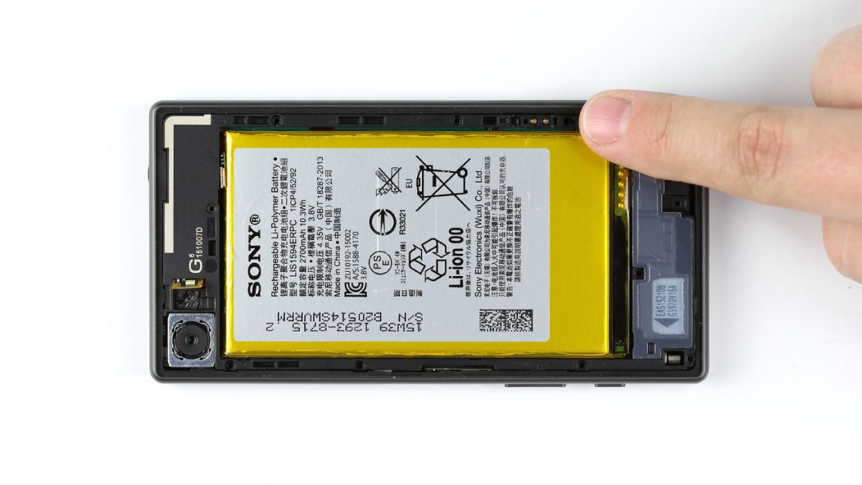
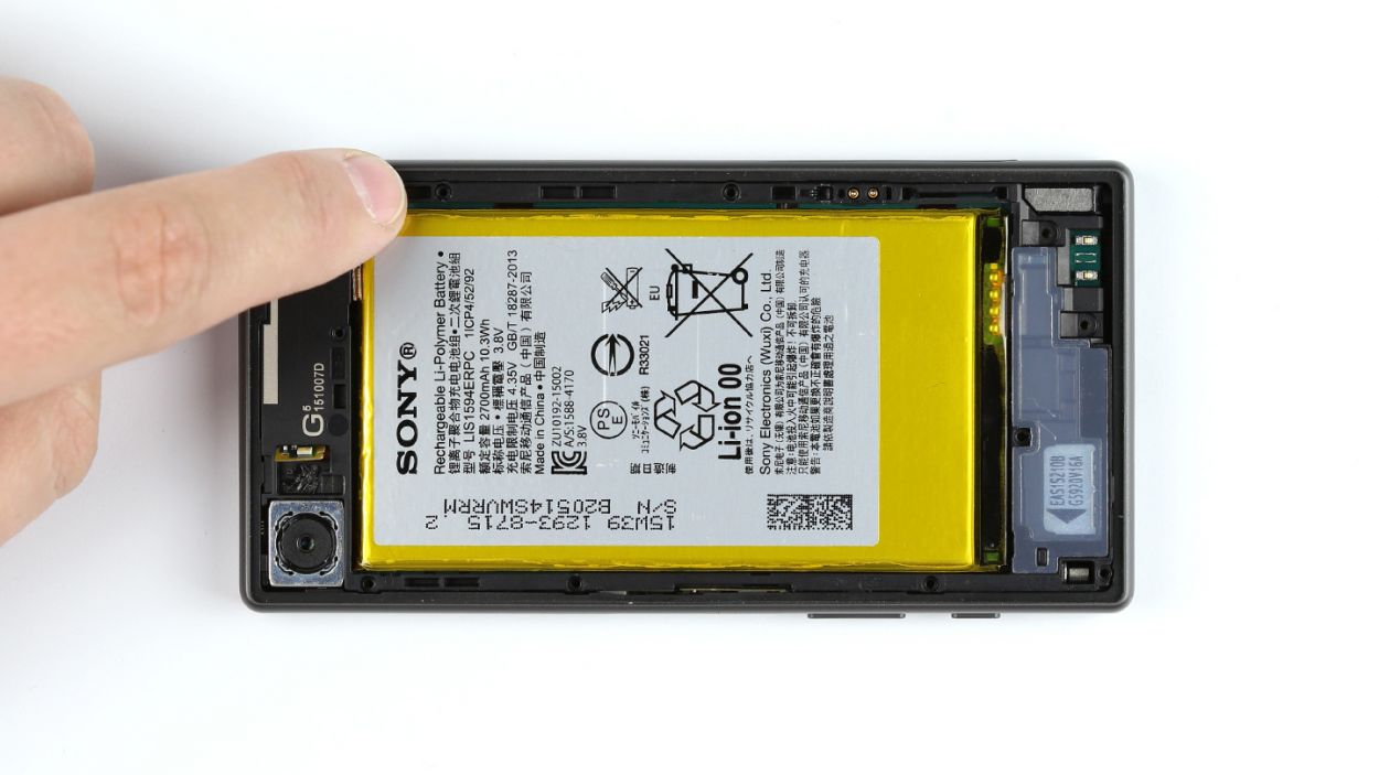
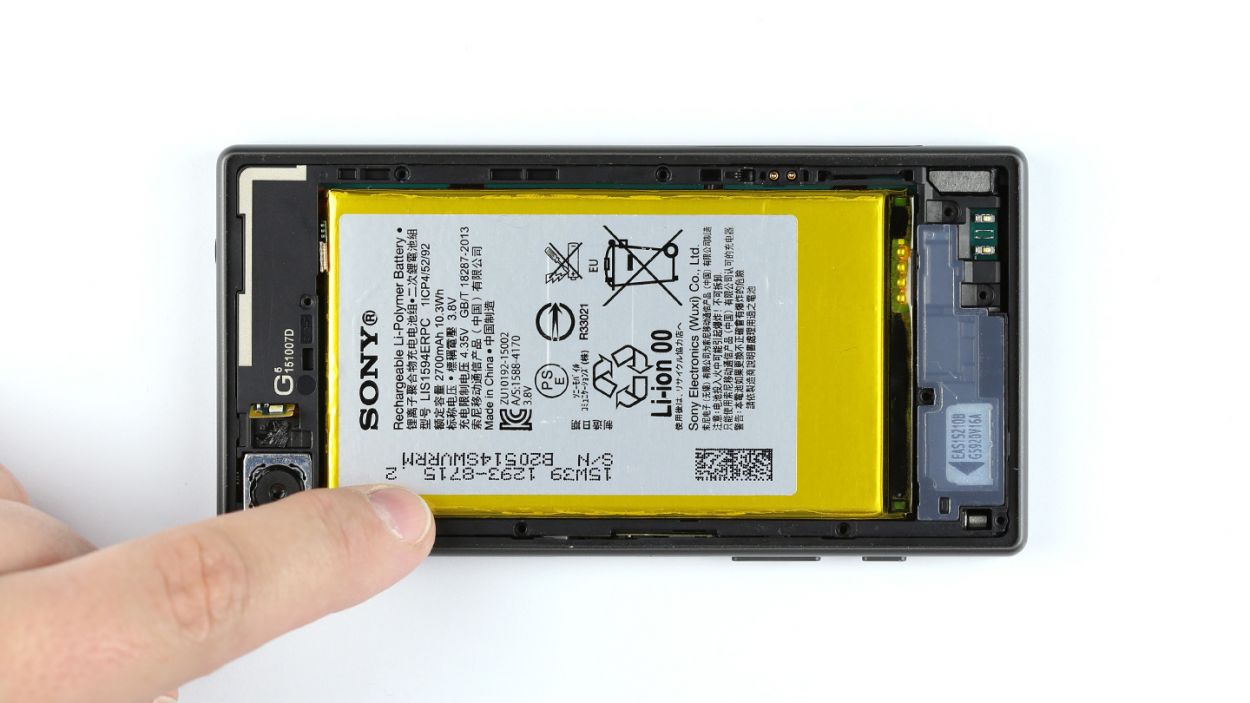
Step 7
– Time to get started! Disconnect that battery contact from the logic board – you got this! If you need help, you can always schedule a repair.
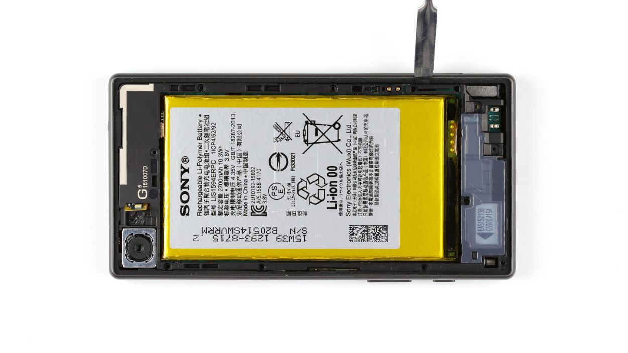
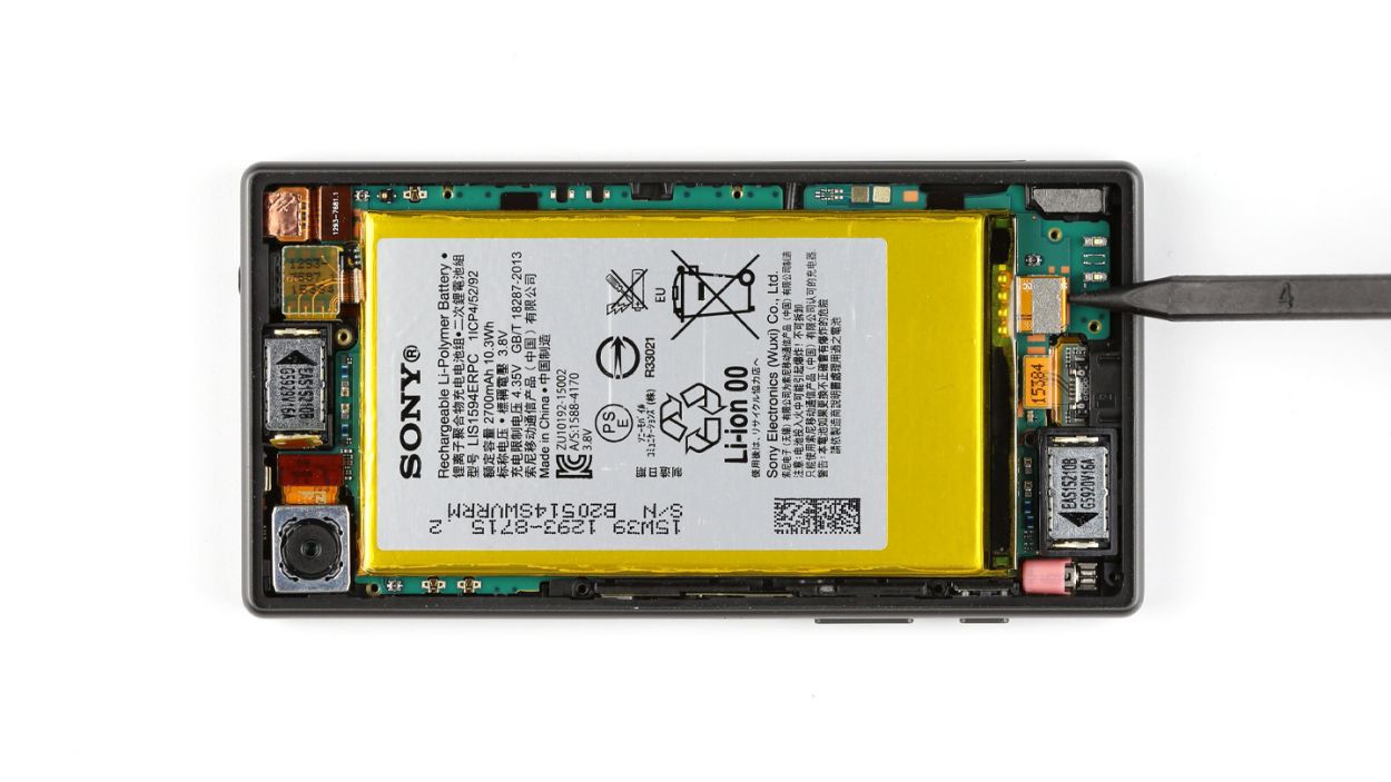
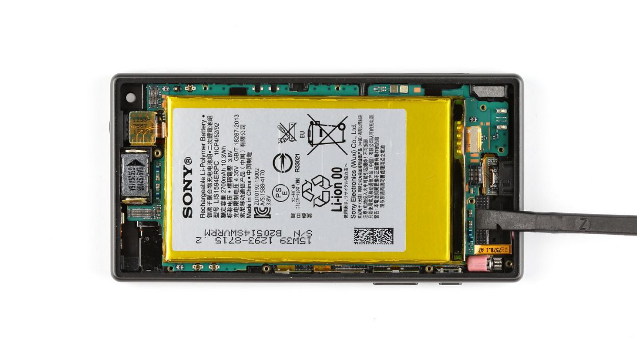
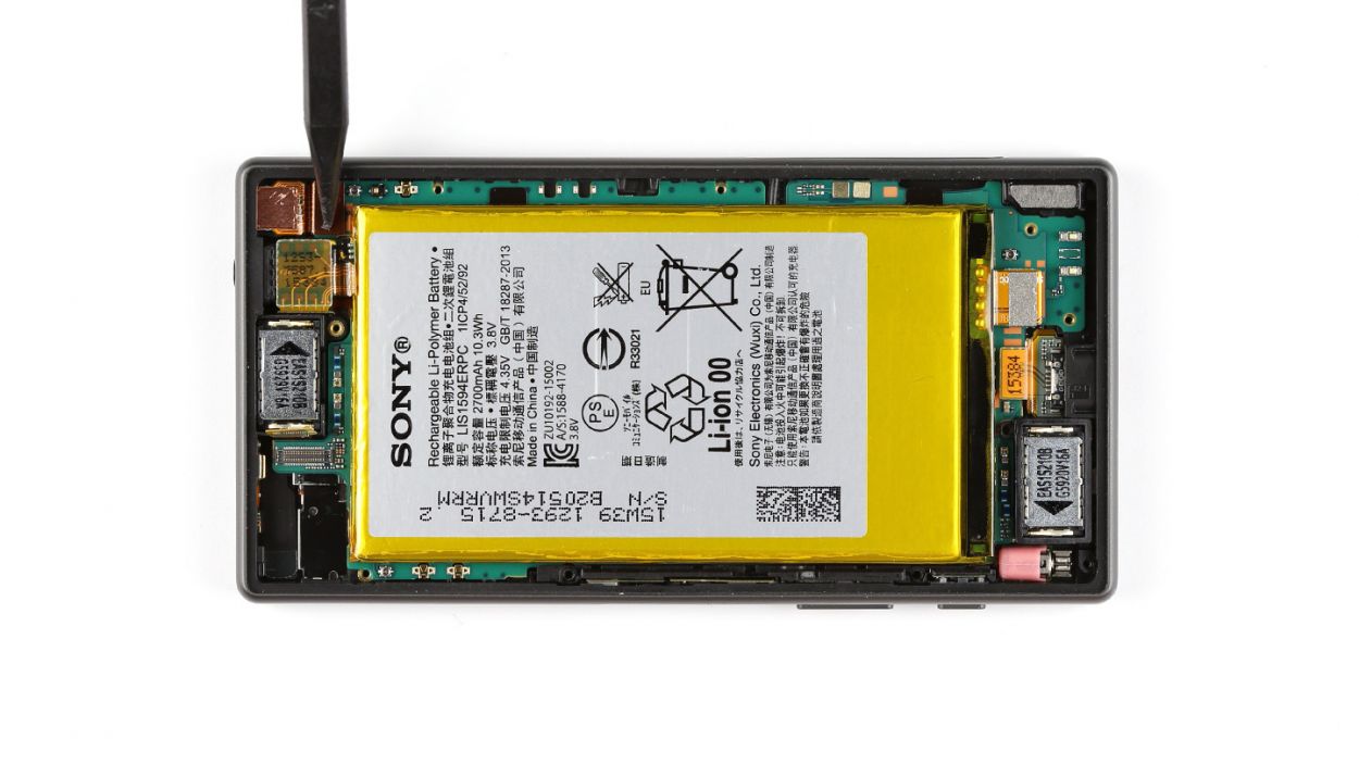
Step 8
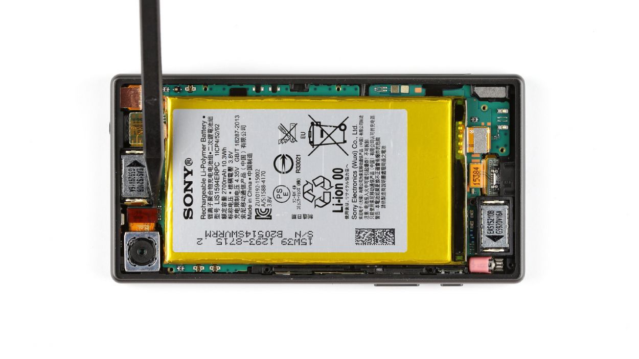

– Gently unplug the rear camera from the logic board, like you’re giving it a little high-five.
– Carefully take out the rear-facing camera, as if you’re lifting a delicate treasure.
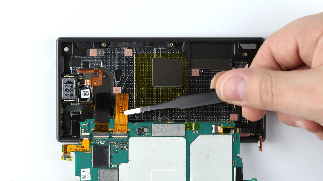
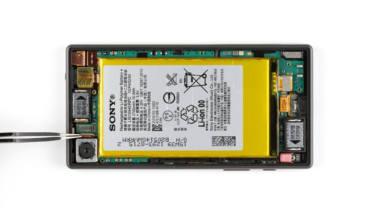
Step 9
– Time to say ‘bye-bye’ to that front camera connection! Gently disconnect it from the logic board.
– Now, let’s give that front camera a little nudge and pop it out of its enclosure. Easy peasy!
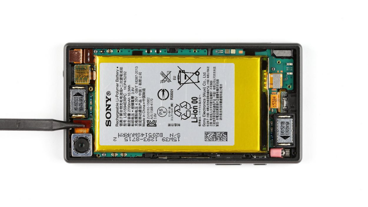
Step 10

– Carefully take out the speaker from its cozy little home in the enclosure.
Step 11
– First things first, unplug that Micro-USB port from the logic board like a pro.
– Grab your trusty steel laboratory spatula and gently wiggle the voice microphone free from the display frame. Easy peasy!
– Now, use that same spatula to lift the vibrator motor out of its cozy spot in the display frame.
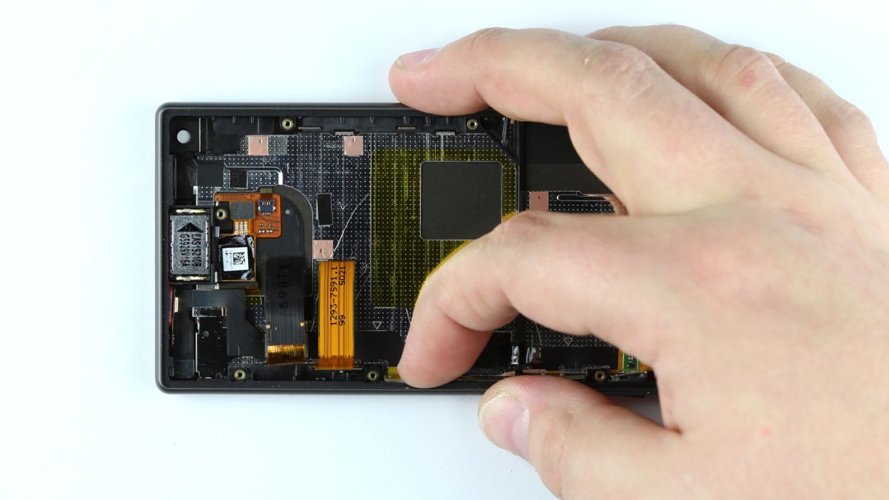
– Time to detach the plastic bar that’s keeping the logic board snug in the display frame. Give it a little tug and remove it.
– Carefully lift the logic board with the flat end of your spudger, and pull it out just a bit from the display frame. You’ve got this!
– Last but not least, disconnect the headphone jack from the display frame. You’re almost there!
Step 12


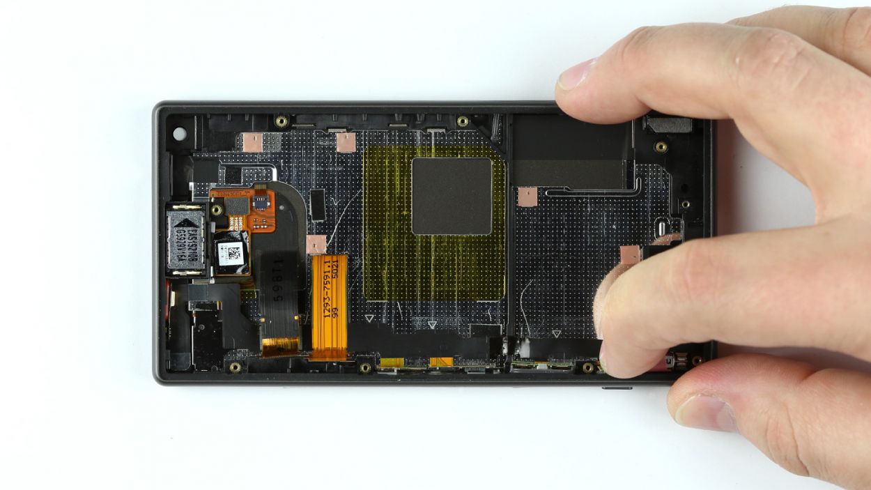
– Alright, let’s get started! The logic board is snugly attached to the bottom of the display. Gently fold it over from the side where the volume rocker switch is hanging out.
– Next up, carefully peel off the polyamide film that’s protecting the contacts. Hold onto that film—it’s going to be your buddy during reassembly!
– Time to disconnect those two display contacts. They’ve done their job, but it’s time for them to take a break.
– Now, let’s liberate them from the logic board. They’ll appreciate the freedom!
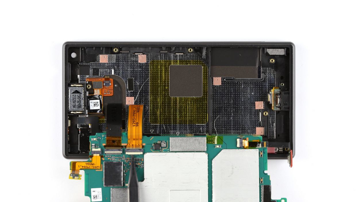
– Finally, go ahead and remove the logic board. You’re doing great!
Step 13
– Grab your trusty steel spatula and gently wiggle it to free the Micro-USB port from the display frame. You’ve got this!
– Now, go ahead and remove that port with confidence!
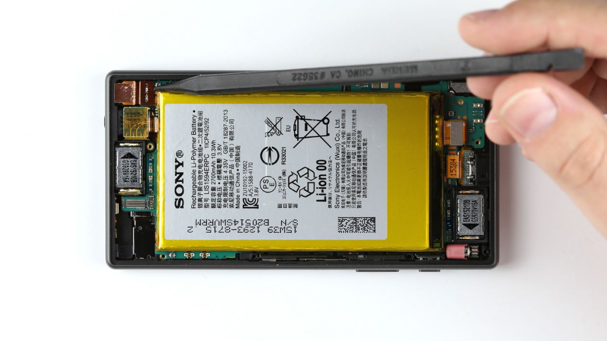
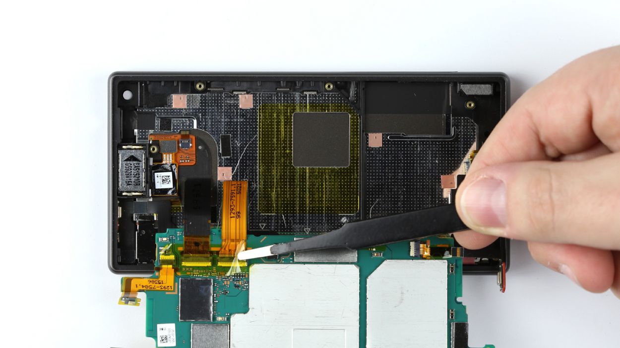
Step 14
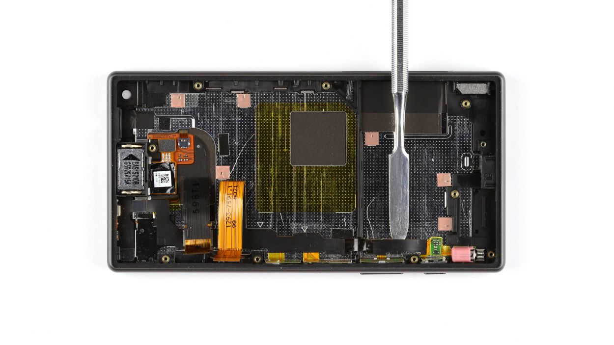
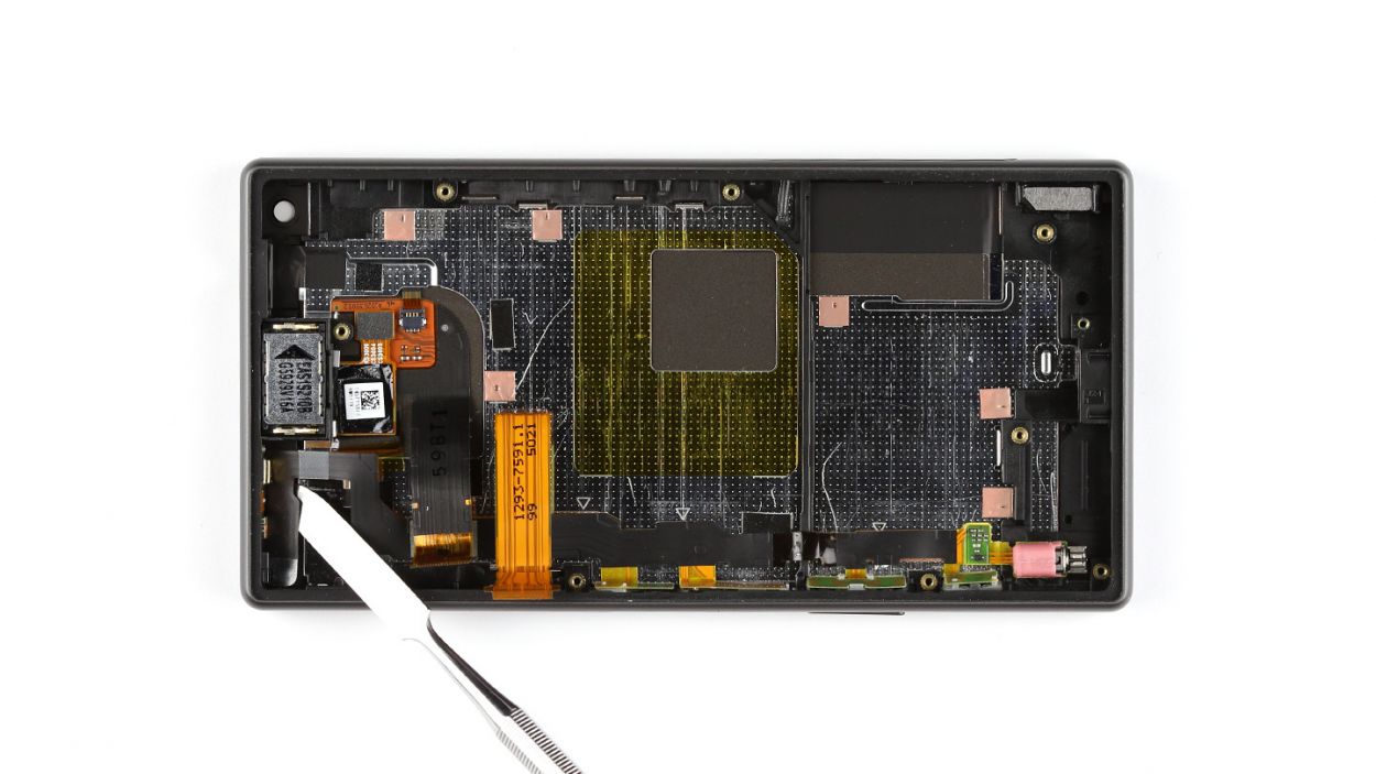
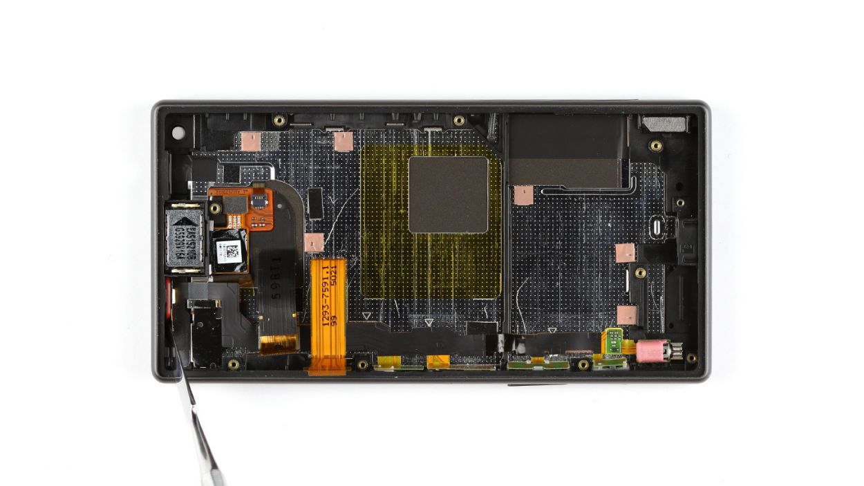
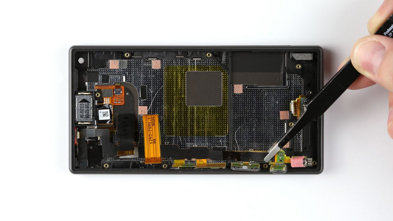
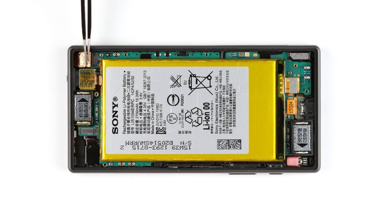
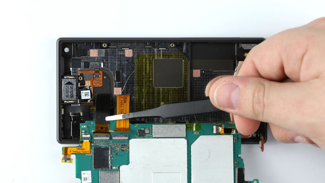
– Grab your trusty steel laboratory spatula and gently pry the flexible flat standby cable away from the enclosure. It might be a bit stubborn since it’s glued on there, so feel free to warm things up a bit if the adhesive is giving you a hard time.
– Next up, let’s disconnect the ambient microphone from its cozy spot in the enclosure.
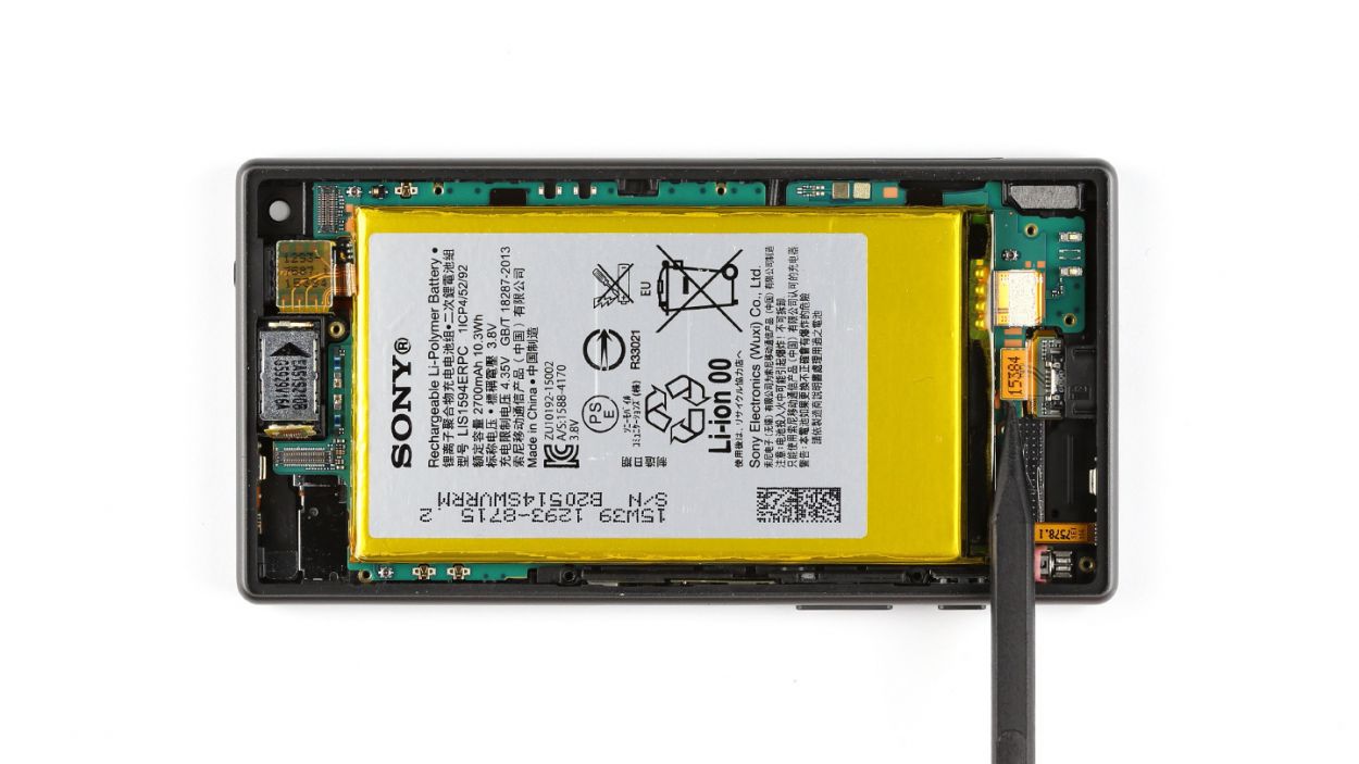
– The control buttons are also sticking to the flexible flat standby cable like they’re best buddies. Carefully separate them so they can go their own ways.
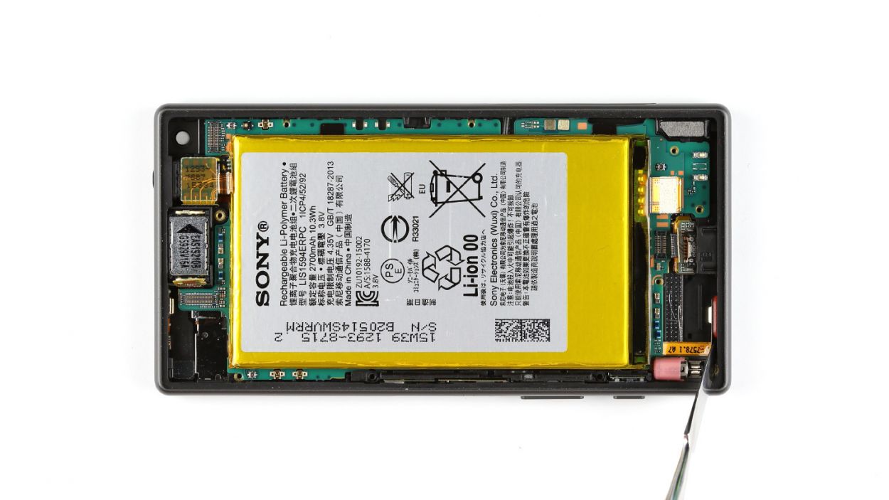
– Finally, it’s time to remove the standby/volume/camera shutter release cable. You’ve got this!
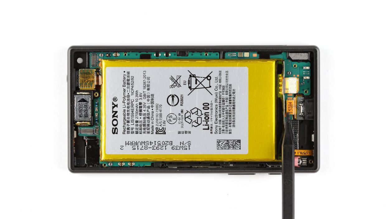
Step 15


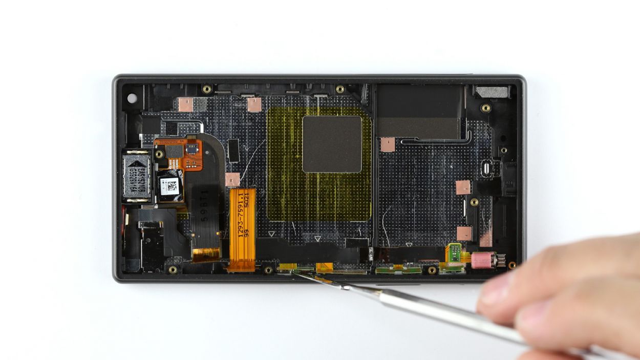
– Carefully place the flexible flat standby cable into its cozy spot in the enclosure.
– Gently guide the ambient microphone back through the display frame like you’re helping it find its way home.
– Give that flexible flat cable a good press down so the glue can really bond with the enclosure—it’s like a warm hug for your device!

Step 17


– Let’s get those display cables connected to the logic board, shall we?
– Next up, it’s time to lay down that polyamide film to keep the display contacts safe and sound. If it’s not sticking like it should, feel free to grab some other tape to help out.
– Now, gently fold the logic board back into its cozy spot. You’re doing great!
Step 18


– Gently guide that headphone jack into its cozy spot in the display frame and slide the logic board back into place.
– Nestle the bar back into the enclosure and use it to give the logic board a secure hug.
– Pop in the vibrator motor and the voice microphone snugly into the enclosure.
– Connect the Micro-USB port to the logic board, ensuring a solid connection.
Step 19
– Pop that speaker into its cozy home in the enclosure, buddy!
Step 20

– Time to get your front camera back in its cozy enclosure! Place it gently inside.
– Now, connect that front camera to the logic board. You’re doing great! If you need help, you can always schedule a repair
Step 21
– Gently place the rear camera back in its cozy spot in the enclosure.
– Make sure to connect the rear camera to the logic board so they can work together!

Step 23


– Gently place the chassis on the display like it’s finding its cozy spot.
– Give the chassis a little press until you hear that satisfying click as it locks into the display frame.
– Secure the chassis to the display using those eight trusty Phillips screws—8 x 4.5 mm Phillips screws to be exact.
– Now, let’s attach the LED flash to the chassis and brighten things up!
Step 24

– Get that main antenna cozy in its little enclosure!
– Secure the main antenna to the device with two Phillips screws—those handy 2 x 4.5 mm Phillips screws will do the trick!
Step 25

– Let’s get that NFC antenna cozy on the battery! Gently press it down so that the glue can make a strong bond again.
– Now, it’s time to connect the NFC antenna’s plug to the chassis. Make sure it’s snug and secure!
Step 26
– Time to get your type plate on! Attach it to the SIM and microSD card slot, and you’re one step closer to getting your device back in action. If you need help, you can always schedule a repair.
Step 27

– Step 1: Time to get reconnected! Position the back cover on the chassis, making sure it clicks into place along all the edges. Press firmly so it’s snug and secure.
– If you need a little extra hold, heat the back of the device. This will ensure it sticks like a charm and helps keep everything in place while you work.
Step 28

– If you’ve closed the cover again, give it a gentle nudge with your finger or a spudger to pop it open. Turning the cover 90° can help you get a better look at that card slot!
– Now it’s time to slide the SIM and microSD cards back into their cozy homes. Just place the SIM card in the tray and you’re all set!
