DIY Guide to Replace Volume Control Cable on Moto X Play
Duration: 30 min.
Steps: 14 Steps
In this guide, we’re here to help you tackle the replacement of your Moto X Play’s pesky volume control cable all by yourself! If your volume rocker switch is feeling a bit lazy or just doesn’t have that satisfying click, it’s time for a change. Plus, if your device refuses to power on, this part might be the culprit. Let’s get started!
Step 1
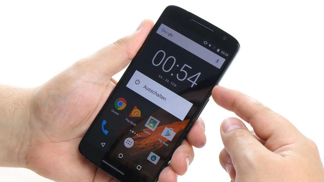
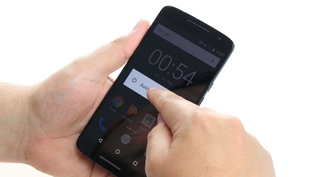
– Time to take a break, device! Hold down that power button until you see the ‘Power off’ option – it’s like giving your phone a little nap.
– Confirm that you’re ready to shut down your Moto X Play, then wait for the screen to go dark. Don’t worry, it’s just a temporary goodbye! If you need help, you can always schedule a repair.
Step 2


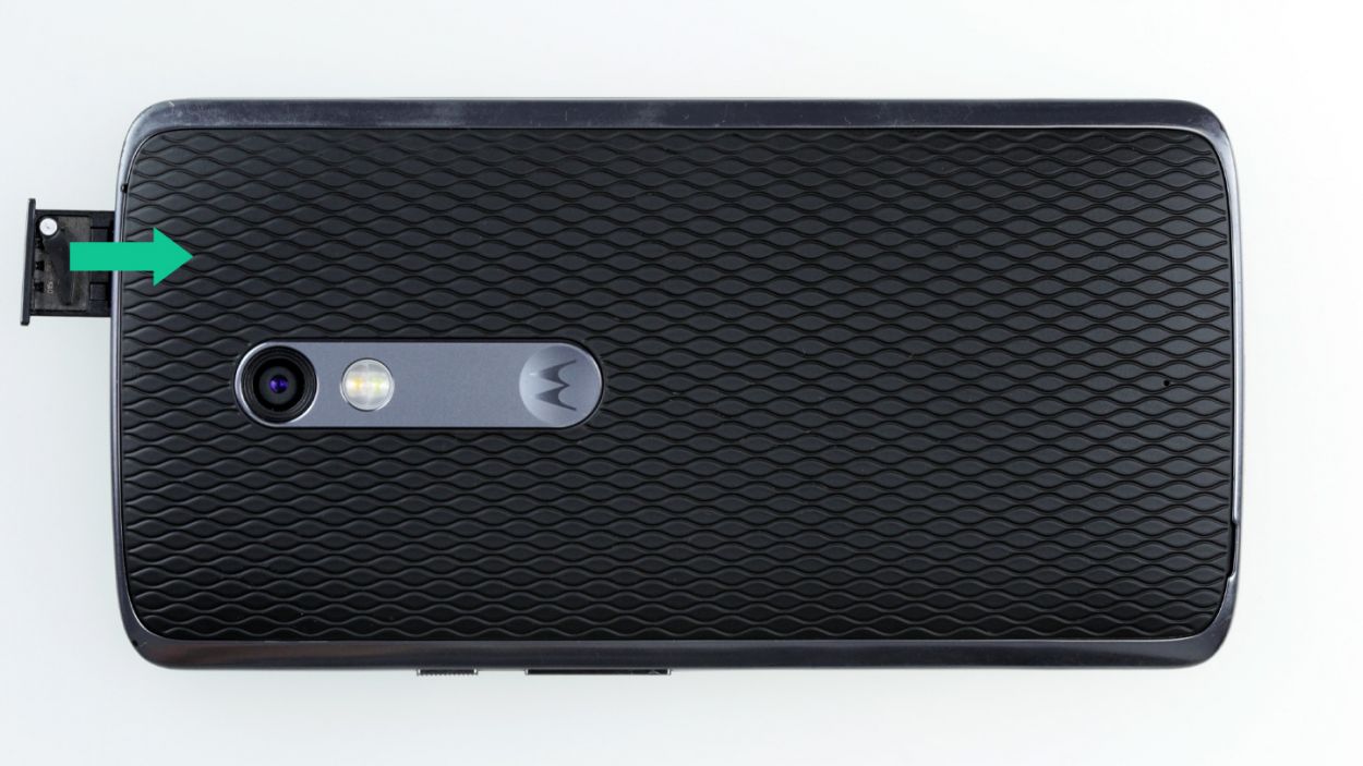
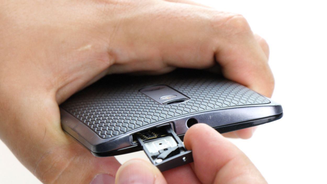
– Pop that SIM tray out of your device! Just grab a SIM tool or a straightened paperclip and give that little hole a gentle poke.
– Once the tray is peeking out a bit, go ahead and pull it out along with the cards. Easy peasy!
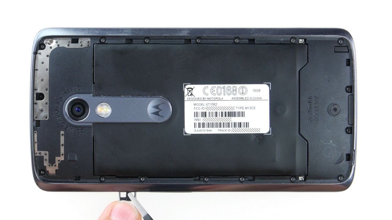
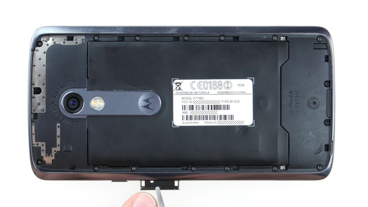
Step 3
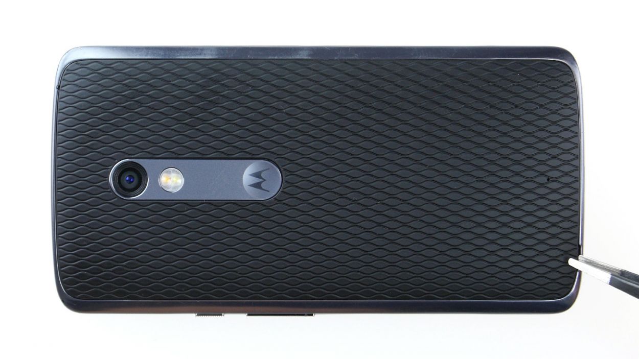
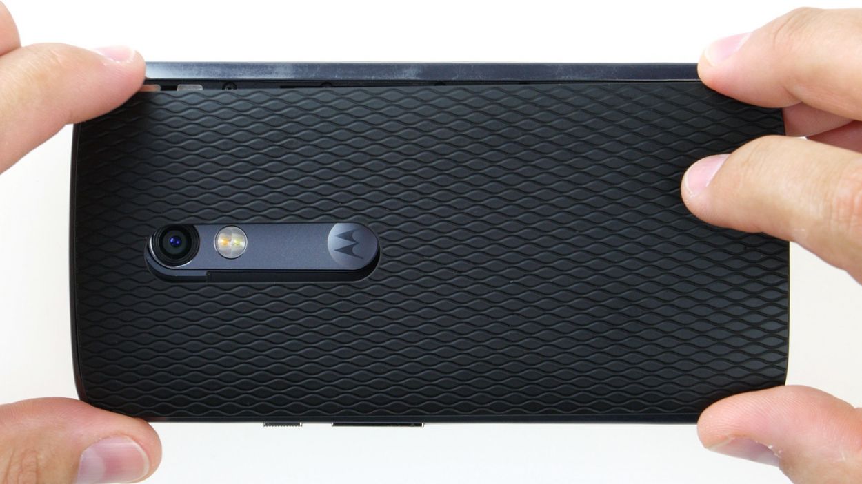
– Look for the long slot in the lower left corner of the back cover. It’s the perfect spot to slide in your fingernail or a handy tool to gently pry the back cover away from your device.
– The cover is secured to the chassis at several points. Carefully release all the hooks and lift the back cover off your device. You’ve got this!
Step 4
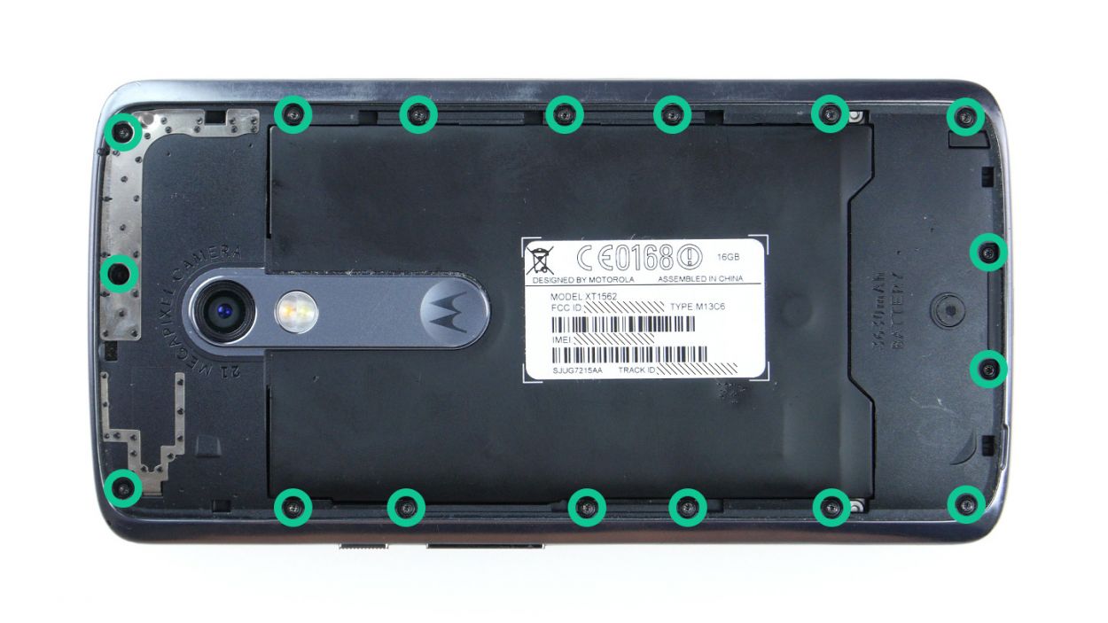
– Let’s kick things off by unscrewing those seventeen screws that hold the midframe snugly in place. We’re talking about 17 x 3.1 mm T3 Torx screws here, so grab your tool and get to work!
– Once those screws are out of the way, gently lift off the midframe. Just a heads up, the power button and volume rocker switch might decide to take a little tumble during this step. If they stay put, no worries—you can always pop them out later!
Step 5
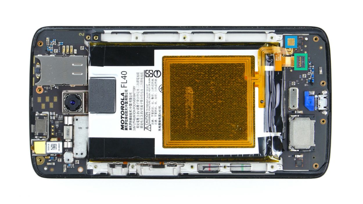
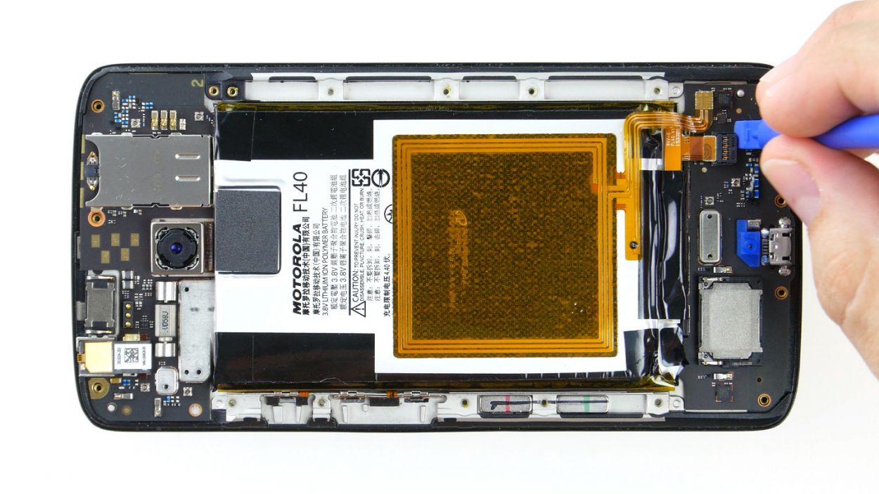
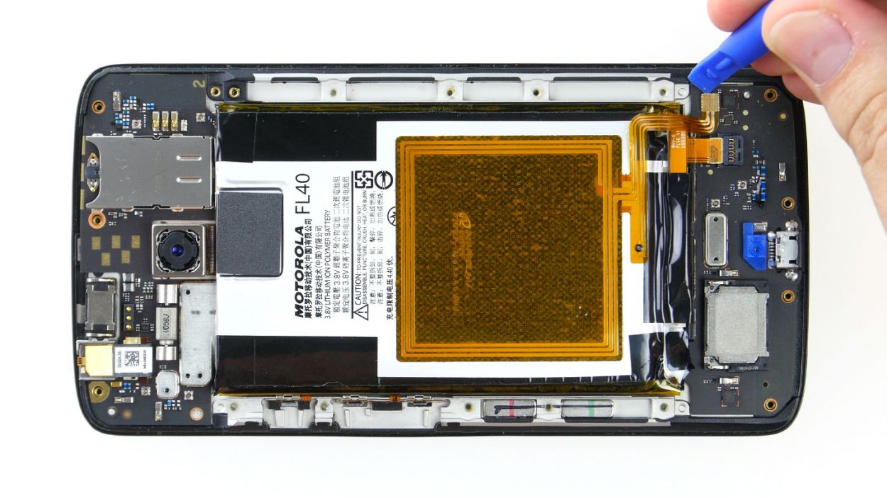
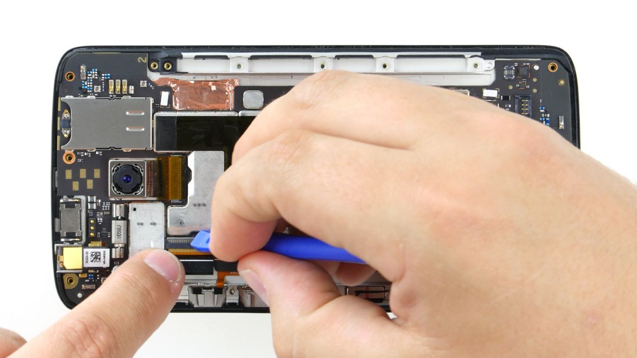
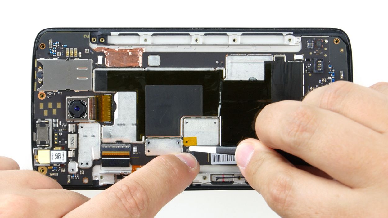
– Let’s give that battery and NFC antenna a little break! Go ahead and gently disconnect the two plug contacts from the PCB. It’s like a little handshake between them—battery, NFC antenna, it’s time to part ways for a moment!
– Now, for the connectors, grab your trusty spudger! Slide the blade underneath the contact and carefully pry it out of the socket. Think of it as nudging a shy friend to join the party—no rush, just be gentle!
Step 6
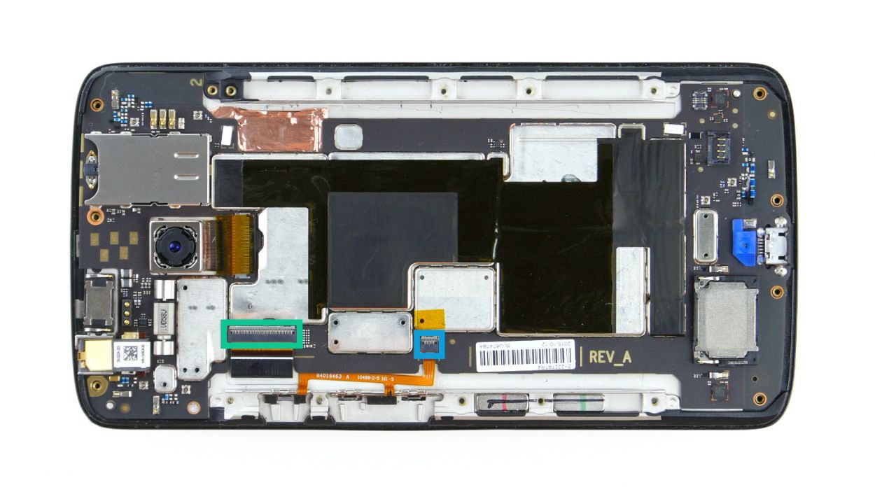
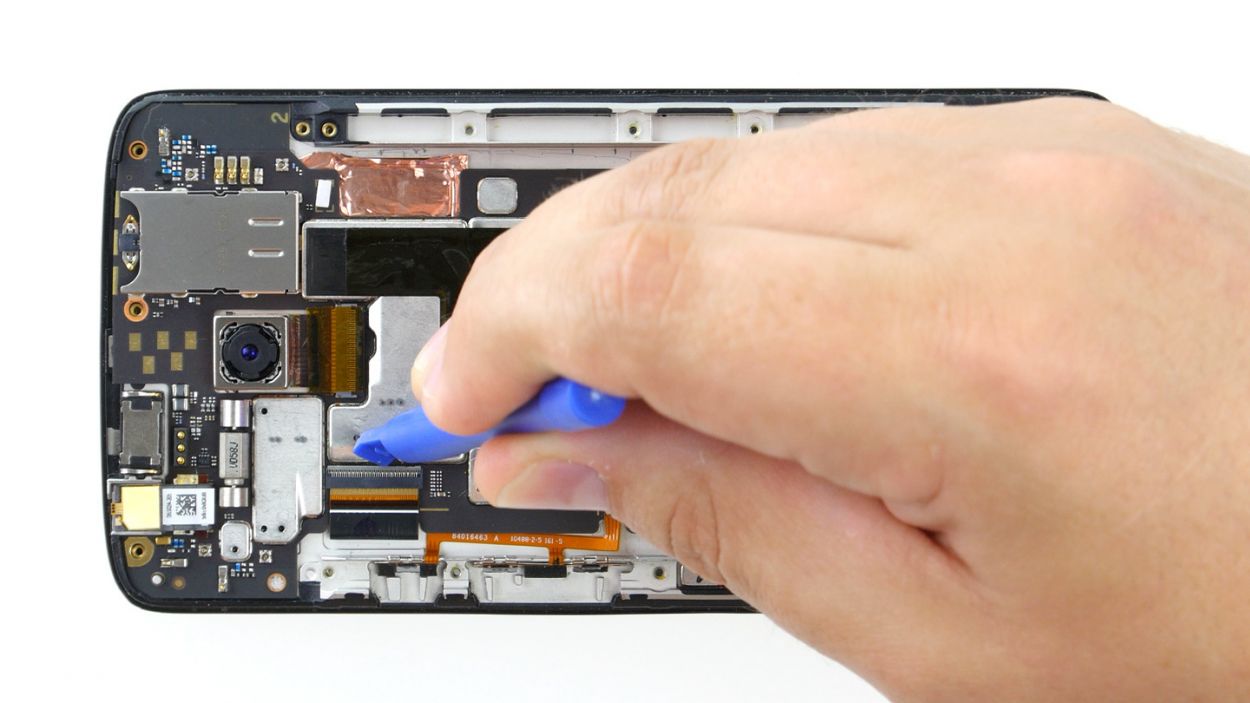
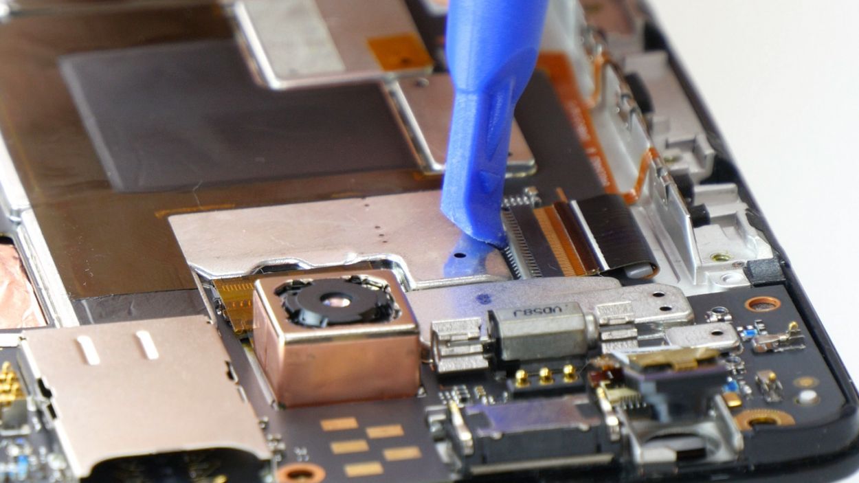

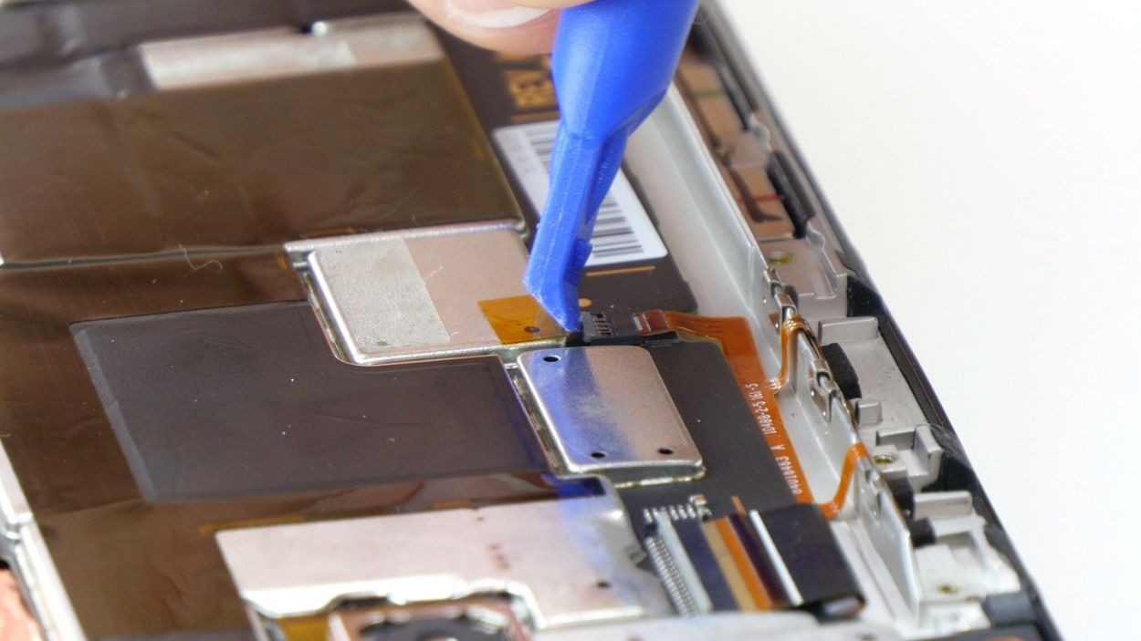
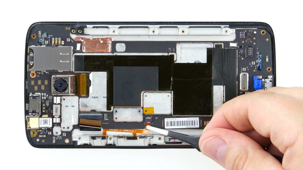
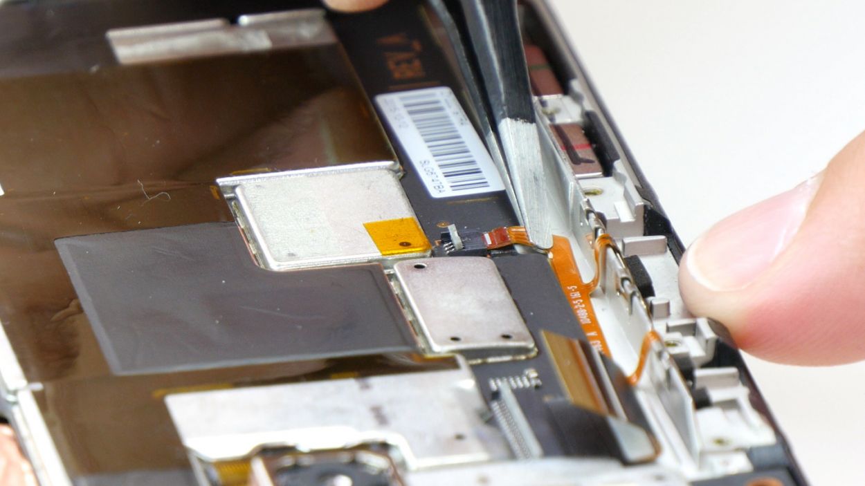
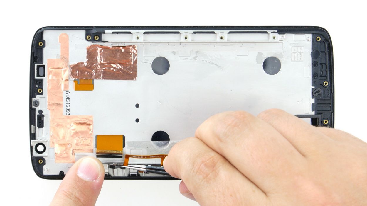
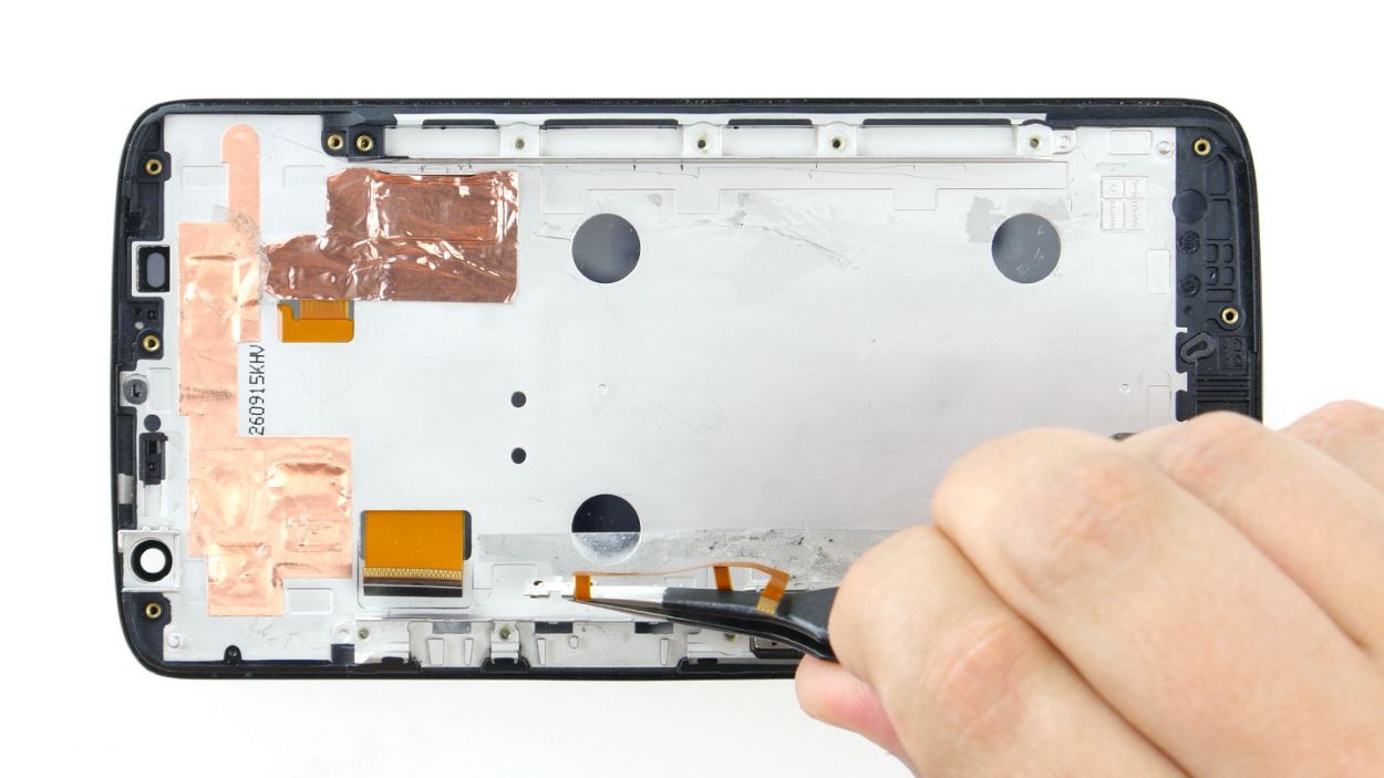
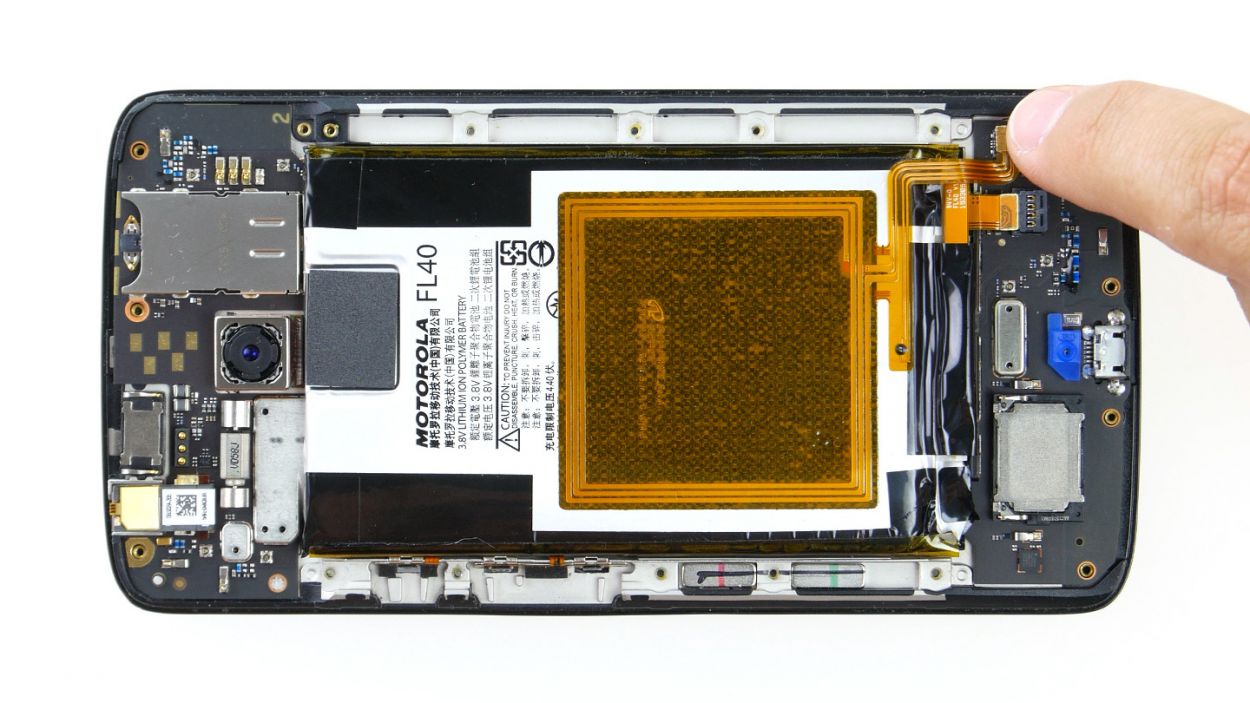
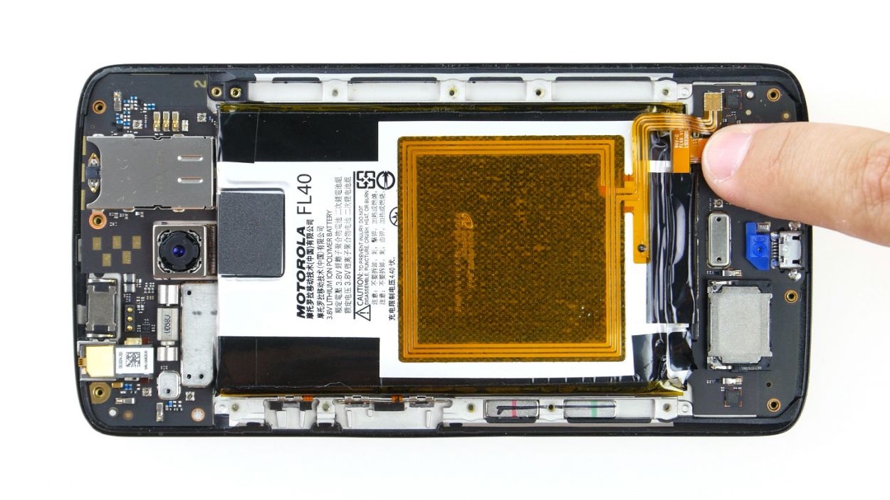
– Unplug those display and button connectors from the mainboard – easy peasy!
– Gently nudge those two brackets off their sockets using your spudger. Think of it as a tiny, polite eviction.
– Time to pull those cables free! Just be super gentle; no need to bend or break anything. If you need help, you can always schedule a repair
Step 7
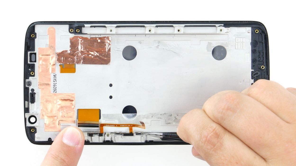
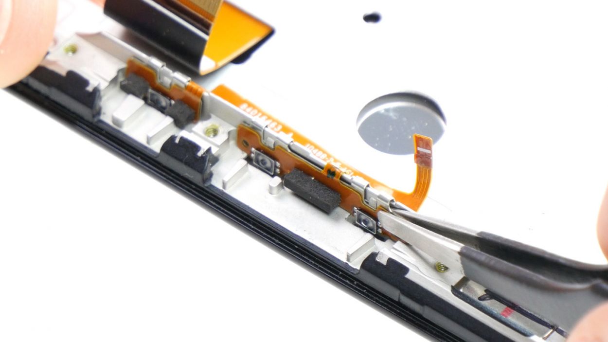


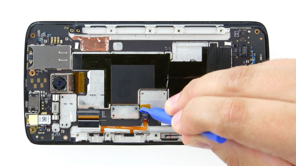
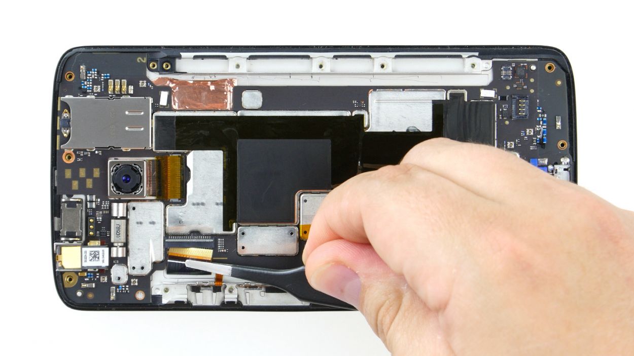
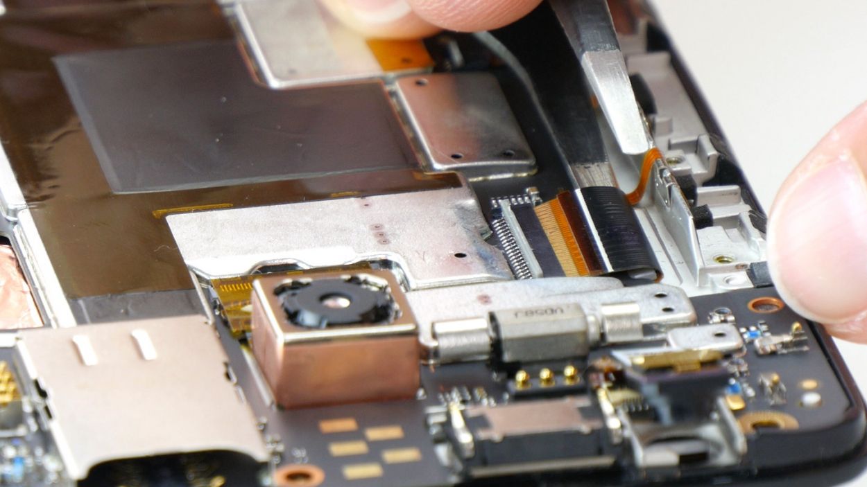
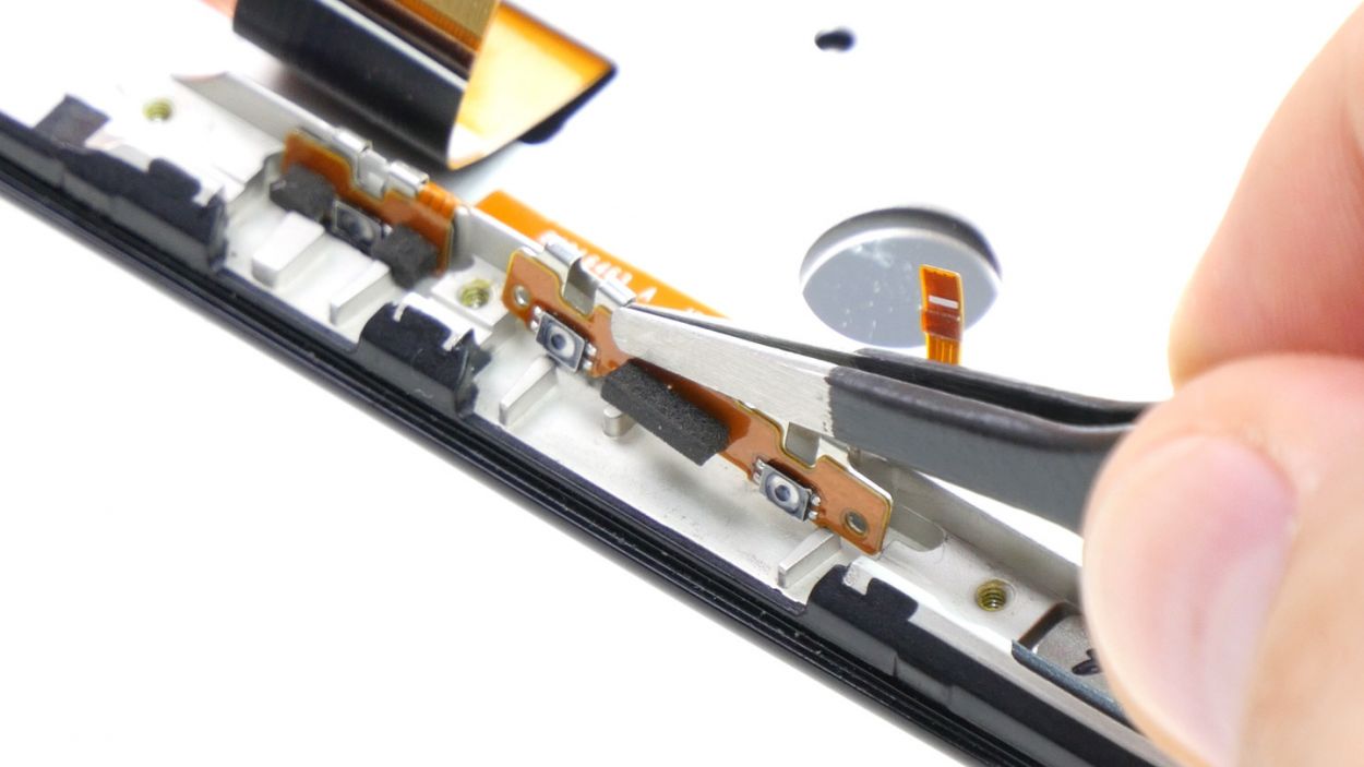
– First up, let’s tackle those control buttons! Each of the three buttons is snugly attached to the metal strip with a bracket and a little tab holding it down. Grab your trusty tweezers and gently slide them between the button and the strip. With a light touch, push the bracket away from the strip and then carefully lift it up. Easy peasy!
– Now, repeat that little dance for the other two buttons. You’ve got this!
– Next, it’s time to remove the volume control cable. You’re doing great!
Step 8


– Place the volume control cable onto the strip. Snap the three brackets securely into position on the strip.
Step 9


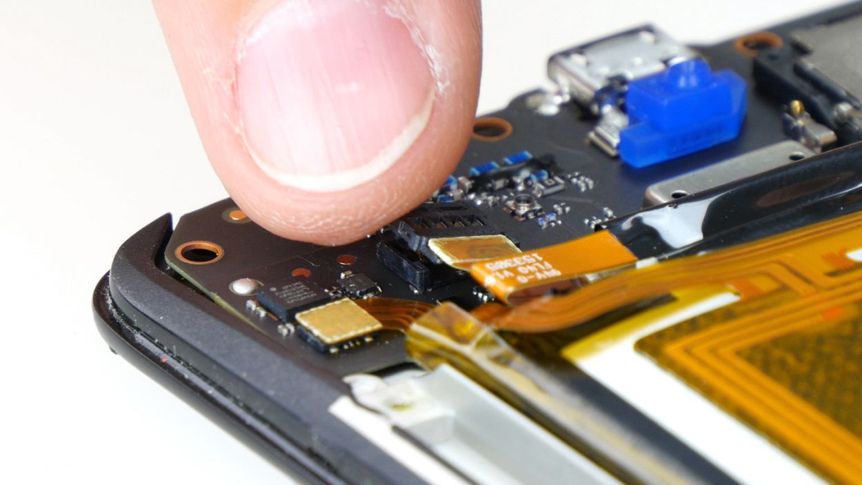
– First up, let’s connect those two plug contacts for the display and the control buttons to the PCB. You’ve got this!
– Now, gently slide each cable back into its matching socket. Make sure to push it all the way in so we get that sweet electrical contact. Just be careful not to bend or damage those cables.
– Finally, give those brackets a little press to lock those cables snugly in place. You’re doing great!
Step 10

– Reconnect the battery contact and the NFC antenna’s connector to the PCB. Just like that! NFC antennaBattery
– Gently press those two connectors into their rightful homes. Listen for that satisfying click – it means they’re snug and secure!
Step 11


– Carefully place the midframe back onto the device, ensuring that all the openings align perfectly with the threaded holes. It’s like fitting the last piece of a puzzle!
– Grab those seventeen screws and secure the midframe to the device. You’ll be using 17 x 3.1 mm T3 Torx screws for this step. Tighten them up and feel that satisfaction of a job well done!
Step 12
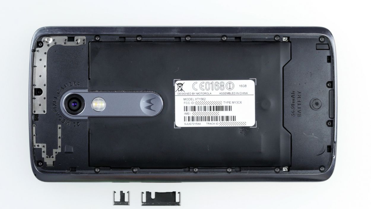
– Remember to pop those two buttons back in for the power and volume control! Just align them like you see in the first picture and slide them into their cozy little spots. You’ll hear a satisfying click as they snap into place in the enclosure. Easy peasy!
Step 13

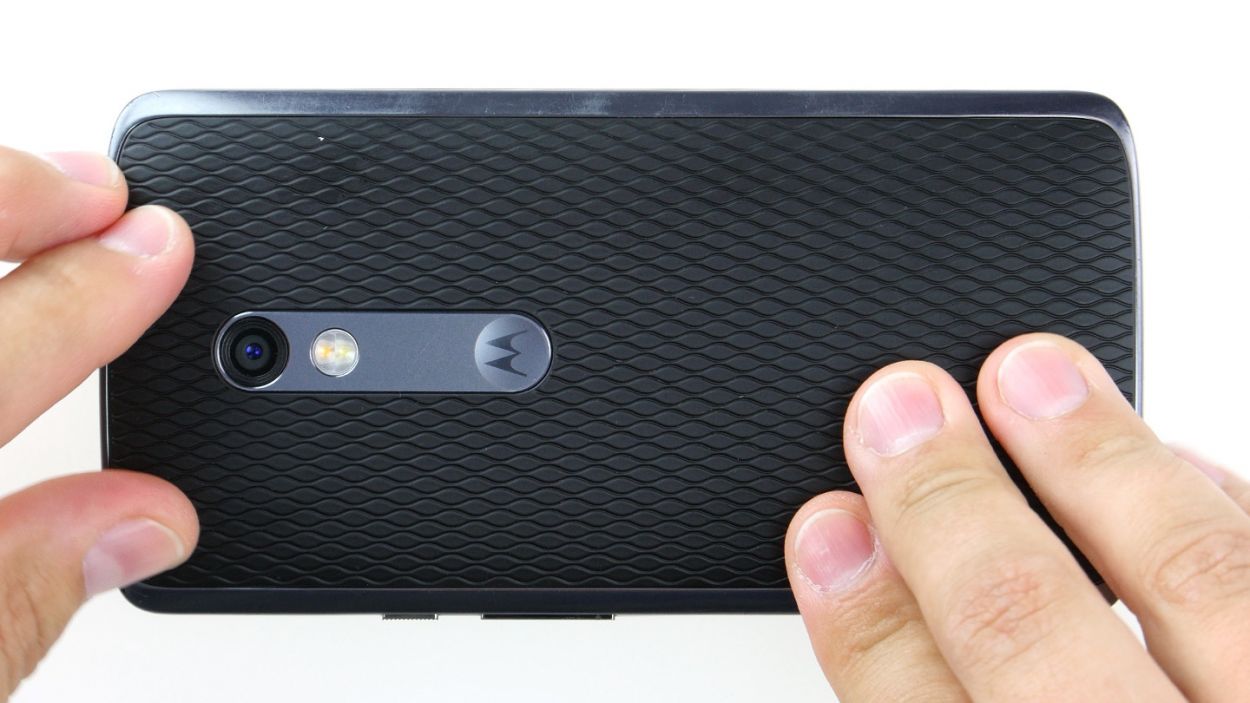
– Gently place the back cover back where it belongs on your device.
– Give that back cover a little love by pressing down all around until you hear those delightful clicks of the hooks locking into place.
Step 14
– Gently slide that SIM tray back into your device, making sure it fits snugly and lines up just right. You’ve got this!