DIY MacBook Pro 13 Logic Board Replacement Guide
Duration: 45 minutes
Steps: 33 Steps
Heads up, friend! Before you start this repair journey, remember that some steps might require a bit more elbow grease than others. If things get tricky or you just want to ensure everything’s perfect, don’t hesitate to schedule a repair with us. We’re here to help keep you grooving with your gadgets!
Get ready to tackle that pesky logic board replacement! Just a friendly reminder to check out our thermal paste application guide before you pop that heat sink back in place. You’ve got this!
Step 1

– Time to tackle those ten screws holding the lower case snugly against the upper case:
– As you embark on this repair journey, keep a close eye on each screw and remember where it belongs. This little habit will help you avoid any mishaps with your device.
Step 2

– Slide your fingers into the groove between the top and bottom sections of the case.
– Carefully and slowly separate the bottom case from the top case. Remember, if you’d rather chill while experts do the work, you can always schedule a repair!
Step 3


The lower case is held snugly to the upper case by a couple of nifty plastic clips right in the middle.
– As you put things back together, give the center of the lower case a gentle nudge to click those two plastic clips back into place. If you need help, you can always schedule a repair
Step 4

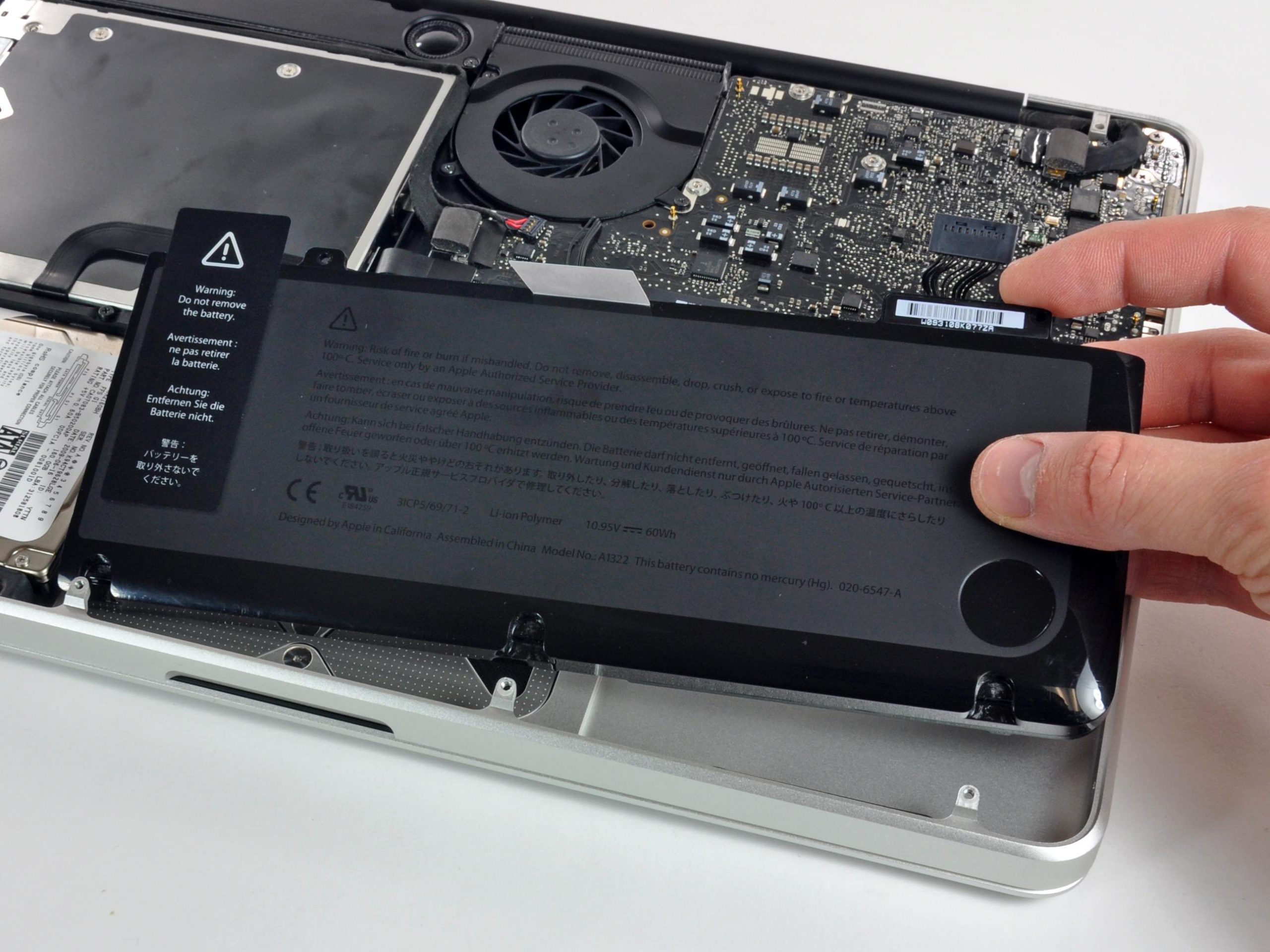
If you need to, peel off that cheeky little plastic cover that’s sticking to the battery contact board. If you need help, you can always schedule a repair.
Step 5


Remember, it’s all about finesse! Gently lift only on the connector itself, not the socket. Treat it like a delicate dance to avoid any permanent harm to the logic board.
– Gently use the flat end of a spudger to pop that battery connector right out of its cozy little home on the logic board.
Tools Used

Step 6

– Lift the battery connector gently and flip it up and away, so it doesn’t get all touchy-feely with its socket while you work your magic. If you need help, you can always schedule a repair.
Step 7


– Gently peel away the rubber fan bumper from the edge of the heat sink. It’s snugly wrapped around, so take your time!
– The fan bumper is designed to hug the heat sink and fit snugly into the fan duct’s slots. When you’re putting everything back together, make sure those tabs slide right into the notches in the fan duct for a perfect fit.


Step 9

– Unscrew the screws that are holding the heat sink tight against the logic board. You’ve got this!
Step 10


– First things first, let’s get that heat sink off your laptop. It’s like giving your device a little breather!
– When you’re putting everything back together, don’t forget to check out our thermal paste application guide to ensure that thermal paste is reapplied just right. Your laptop will thank you!
Step 11


– Gently nudge the iSight camera cable connector on both sides with the spudger tip to ease it out of its cozy spot on the logic board.
Tools Used
Step 12


– Gently lift the iSight camera cable off the fan housing and tuck it away for now. You’ve got this!
Step 13


– Gently pop the fan’s ZIF connector tab up using the tip of a spudger—like you’re flipping the coolest little switch.
– Then, with the grace of a ninja, pull the fan cable straight out from its socket. Stay smooth, and if you need help, you can always schedule a repair.
Tools Used

Step 15


– Gently lift the end of the fan closest to the display hinge and glide it out from the upper case. If you need help, you can always schedule a repair.
Step 16


– Let’s get those two 2.1 mm T5 Torx screws out of there! They’re the ones keeping the I/O board cable bracket attached to the logic board.
– Now, gently lift away that I/O board cable bracket. You’re doing great!
Step 17


Hey there! Make sure you’re only prying up the I/O board cable and not messing with the socket itself. We don’t want any logic board drama, right? If you need help, you can always schedule a repair.
– Gently nudge the I/O board connector upwards using the flat end of a spudger to detach it from its cozy spot on the logic board.
Tools Used
Step 18


Hey there, be gentle with that cable! Only fold it at the bendy part near the I/O board end. If you need help, you can always schedule a repair.
– Gently take the end of the I/O board cable and lift it upwards, just like you’re doing a little cable-yoga, to get it out of your way. If you need help, you can always schedule a repair.
Step 19

– Grab the pointy end of a spudger and gently pop that right speaker connector up out of its slot on the logic board. Remember, it’s like unplugging a tiny speaker buddy, so be gentle! And hey, if you need help, you can always schedule a repair.
Tools Used
Step 20

– Using the tip of a spudger, gently nudge both sides of the I/O board connector to coax it out of its cozy spot on the logic board.
Tools Used
Step 21


– Grab the flat end of your spudger and gently disconnect the keyboard backlight cable. Then, bend it up and out of the way of the logic board, so we can keep things tidy while we work our magic!
Tools Used
Step 22


– Gently lift the black tab to unlock the display cable connector and slide it straight out from its spot on the logic board. If you need help, you can always schedule a repair.
Step 23


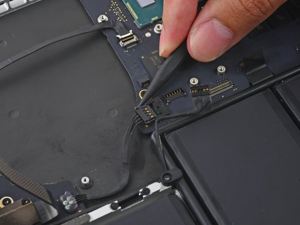
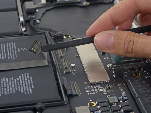
– Gently wiggle the DC-In board connector straight out of its socket on the logic board. You’ve got this!


Step 25

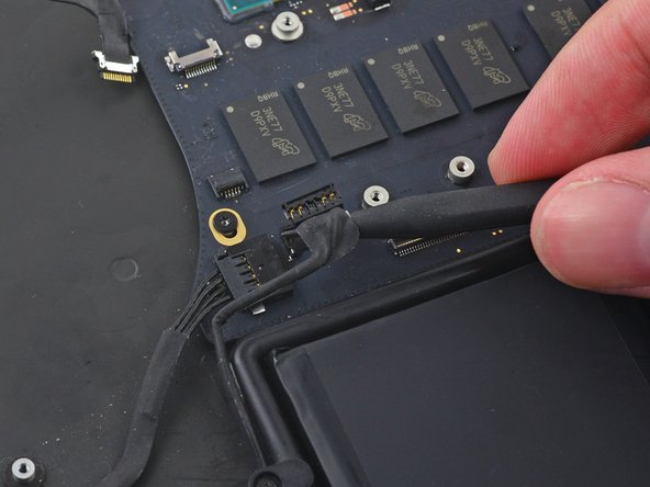
Gently peel away any tape that’s playing peek-a-boo with the microphone cable connector. If you need help, you can always schedule a repair.
Step 26


– Grab your trusty spudger and carefully pop up the retaining tab on that ZIF connector for the microphone cable. Nice, right?
– Now, smoothly slide the microphone cable right out of its little home on the logic board. You’re doing great! If you need help, you can always schedule a repair.
Tools Used


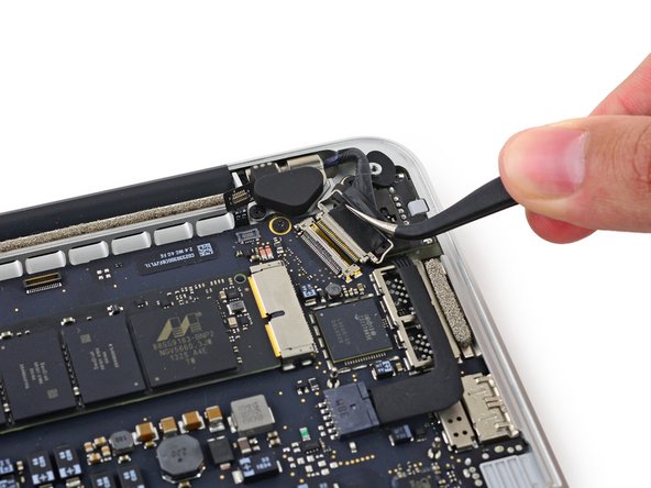
Step 28


– Gently pull the keyboard cable straight out of its ZIF socket on the logic board. If you need help, you can always schedule a repair.
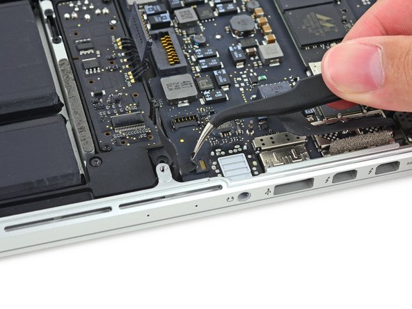
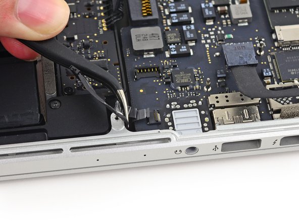
Step 29


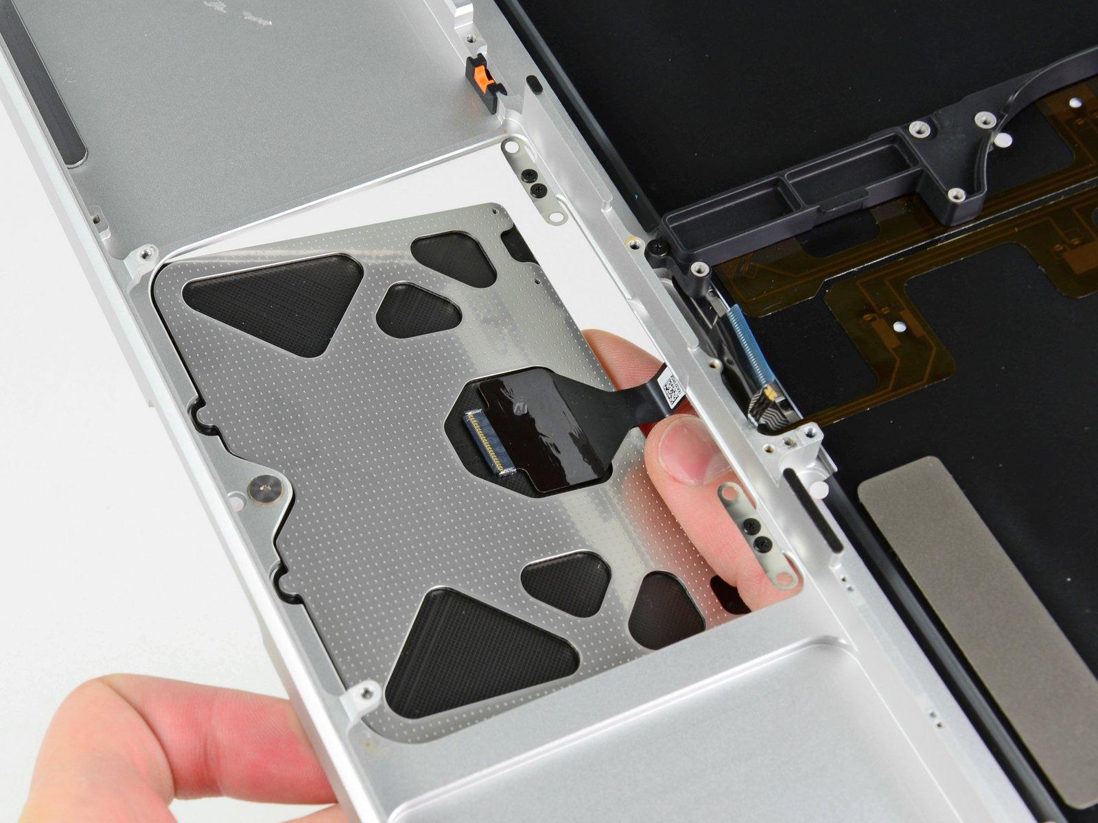
– Grab the flat end of a spudger and give that trackpad connector a quick pop straight up from its socket on the logic board. Easy peasy!
– Now, with a bit of flair, fold the cable back over the battery to make way for the logic board. You’ve got this!
Tools Used
Step 30

– Alright! Time to loosen up and get those five 3.5 mm T5 Torx screws out of the way to free the logic board from the upper case. You’ve got this! If you need help, you can always schedule a repair.
Step 31


– Gently lift the processor side of the logic board a tad and nudge it towards the fan area to release the ports from the side of the upper case. You’ve got this!
– Take out the logic board like a pro. Need help? You can always schedule a repair.
Step 32

– Let’s get that SSD freed up! First, locate the tiny 2.9 mm T5 Torx screw holding it to the logic board. Once you’ve spotted it, carefully remove it using your trusty T5 Torx screwdriver. Easy peasy!
Step 33


– Gently lift the free end of the SSD a bit and slide it straight out of its cozy home on the logic board.