DIY MacBook Pro 14″ Late 2023 Headphone Jack Replacement Guide
Duration: 45 minutes
Steps: 63 Steps
Heads up! Before you dive into the repair, remember to power off your device to avoid any electric surprises! Safety first, fun repair second!
Follow this guide to swap out the headphone jack on your MacBook Pro 14″ late 2023 (M3 Pro and M3 Max). While some pictures might hail from a different model and show minor differences, they’re just as effective in guiding you through the process. Rock on and repair!
Step 1


Get your MacBook’s energy level low, like below 10% low, before kicking off this repair. Just a heads up, a fully juiced battery can go all fireworks on you if it gets poked wrong. Safety first, right?
– Power down your MacBook, snap the lid shut, and flip that baby over. Keep the lid shut tight until the battery is completely disconnected.
– Yank out the MagSafe cable and any other gadgets hitching a ride on your MacBook.
Step 2


Before we jump in, make sure your MacBook Pro is turned off and unplugged. Close the lid, flip it over, and let’s get this party started!
As you dive into this repair, make sure to track each screw like a treasure map and place them back in their original spots to avoid any unwanted surprises with your device.
– Grab your P5 Pentalobe driver and unleash your skills on those eight screws holding the lower case tight. Let’s get them out!
Step 3


– Stick a suction cup near the front side of the lower case, right between those pesky screw holes.
– Give that suction handle a hearty tug upwards to coax a wee gap under the lower case.
Tools Used

Step 4


– Pop in an opening pick into the space you just created.
– Whizz that pick around the nearest corner and cruise it halfway up the side of your MacBook Pro.
Step 5


– Let’s do that dance one more time! Grab your opening pick and shimmy it down the other side to free that second clip. You’ve got this!
Step 6


Those sneaky sliding clips along the back edge of the MacBook are holding on tight! You might need to flex those muscles and put in some elbow grease to pop them off—consider rocking some gloves to keep your hands safe from those pesky sharp edges.
– Gently tug the lower case away from the back edge, one corner at a time, to pop those sliding clips out of their sneaky little hiding spots.
Step 7


– Pop off that lower case, champ!
– When it’s time to put it back: simply reverse the magic!
Step 8


– Gently peel away any tape that’s hiding the battery board data cable connector on the logic board. It’s like uncovering hidden treasure!


Step 10


– Slide out the battery board data cable from its cozy home on the logic board to disconnect it. Easy peasy!
Step 11

While your MacBook might play it cool with some fancy Torx Plus screws, don’t worry, your regular Torx bits will do the trick just fine. Just remember to keep that pressure steady and firm—no stripping allowed, we’re keeping things classy!
– Grab your T3 Torx driver and whisk away those two tiny 2.1 mm-long 3IP Torx Plus screws holding down the trackpad cable bracket right onto the logic board. Easy peasy!


Step 13


– Grab your spudger and pop off the trackpad cable’s press connector from the logic board like a pro!
To snap these press connectors back into place like a boss, line them up and gently press down on one end until you hear that satisfying click, then give the other side the same love. Remember, pressing in the middle is a no-go—it’s like stepping on a garden hose, it just won’t work and you could end up with bent pins. Take care to align it perfectly to avoid turning your tech into a fancy paperweight.
Tools Used


Step 15


– Gently peel back any tape hiding the battery board data cable connector. It’s just chilling under the big pancake screw!


Step 18


The battery board data cable just loves to stick around. A gentle nudge should persuade it to let go.
Step 19

– Grab your T5 Torx driver and zip out the 3.8 mm 5IP Torx Plus wide-head screw that’s keeping the battery power connector in place.
Step 20


Pop that connector up just enough to keep it from getting frisky during your repair—aim for no more than a cheeky 45 degrees to avoid any hinge drama!
For an extra touch of safety, slide something like a playing card piece between the connector and board—it’s a smooth move!
– Grab your trusty spudger and use its flat end to gently pry the battery connector off its board. Whoop! You’ve just disconnected the battery.
Tools Used
Step 21


– Grab your T3 Torx screwdriver and show those three 2.1 mm screws who’s boss! Unscrew them to free the antenna board bracket and the coaxial cable cover from their frame-y prison.
Tools Used

Step 22


– Grab your tweezers or just use your fingers to gently lift off the cover from those snazzy antenna bar’s coaxial cables.
Step 23


– Grab your spudger and gently lift the antenna bar’s coaxial cable to disconnect it.
– Do the same for the remaining two cables.
– When putting it all back together, reconnecting these can be a bit of a puzzle. Just position each connector right above its socket and press down using your spudger’s flat side. You should hear a satisfying click when each snaps into place.
Tools Used


Step 25


– Grab your tweezers or just use your fingers to whisk away those two pesky screen cable covers from the logic board. It’s like magic!
Step 26


– Grab your trusty spudger and gently pop off the right-most screen cable press connectors from the logic board. It’s like disconnecting the world’s smallest puzzle piece!
Tools Used
Step 27


Avoid prying near those surface-mounted buddies next to the press connector; we don’t want any accidental chip parties!
– Now, let’s do that disconnect dance once more with the other press connector chilling at the top left of the logic board.
Step 28


– Gently lift any tape hiding the microphone cable connector. It’s like uncovering hidden treasure!


Step 30


– Slide the microphone cable right out of its cozy socket on the logic board like you’re pulling a magic trick!
Step 31


– Grab your T3 Torx driver and get ready to unleash those nine 2.1 mm screws that are holding the right cable covers hostage on the frame!
Step 32


– Grab your tweezers or just use your fingers to jazz away those five right cable covers. Let’s keep it neat and tidy, folks!
Step 33


– Gently peel away any tape that’s hiding the right speaker cable.


Step 37


– Grab your spudger and let’s gently pop off the right USB-C ports’ press connectors like a boss!
Tools Used


Step 40


– Grab your T3 Torx driver and zip out those four screws holding the left cable covers tight to the frame!
Step 41


– Grab your tweezers or just use your fingers to whisk away those two pesky left cable covers.
Step 42


– Gently coax the tape off the left speaker cable like you’re peeling a banana for a snack. Easy does it!


Step 44


– Gently slide the left speaker cable out of its cozy socket on the logic board to disconnect it. You’ve got this!
Step 45


– Grab your spudger and gently pop off the left USB-C port’s press connector like a pro.
Tools Used
Step 46


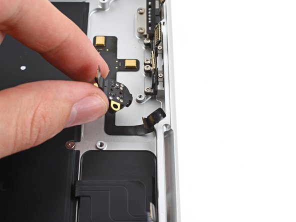
The Touch ID sensor cable is snug as a bug on the frame. If the sticky stuff doesn’t let go when you pop off the press connector, just slide an opening pick beneath the cable to gently persuade it to part ways.
– Grab a spudger and gently pop off the Touch ID sensor’s press connector located towards the top left corner of your gadget.
Tools Used
Step 47


– Gently lift any tape hiding those sneaky keyboard and keyboard backlight cable connectors.
Step 48


– Grab a spudger and gently coax the locking flap on the ZIF connectors for the keyboard cables to pop open. It’s like whispering sweet nothings to them!
Tools Used
Step 49


– Slide out the keyboard and keyboard backlight cables from their cozy homes on the logic board. Just gently tug them free and voilà!


Step 53


The right fan cable has a bit of a sticky relationship with the logic board. Just a heads up!
– Grab your tweezers and gently pull the fan cable from the logic board. It’s just a little sticky from the adhesive, so show it who’s boss!
Step 54


– Now, let’s give the left fan the same superstar treatment! Just repeat the disconnect and shuffle steps you rocked before.


Step 56


– Grab your T5 Torx driver and get ready to unleash those 11 screws holding the logic board in place. Let’s make this board free!
Step 57


– Grab your T6 Torx driver and unscrew those three little rascals holding down the logic board!
Step 58


– Wedge a spudger into the right side gap between the logic board and the frame.
– Give the spudger a little twist upwards to pop the logic board free from its snappy clips.
Tools Used
Step 59


– Wedge a spudger between the frame and the bottom of the logic board to get things started.
– Give the spudger a gentle pry to pop the logic board out of its snug clips.
Tools Used
Step 60


– Carefully hoist the logic board from the right side—like lifting a slice of pizza—to free it from its snug little pegs.
– Scooch the logic board away from the device’s left side to disconnect those HDMI and SDXC ports from their cozy slots in the frame.
– Eject the logic board. It’s free!
Step 61


– When you’re putting things back together, rock these steps:
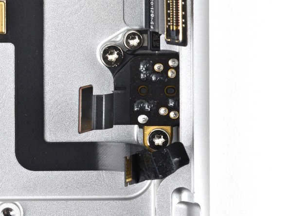
Step 62


– Grab your T5 Torx driver and unscrew those two little rascals holding down the headphone jack!