
DIY MacBook Pro 15 Core 2 Duo Model A1211 Clutch Cover Replacement Guide
Duration: 45 minutes
Steps: 37 Steps
Heads up! Before you dive in, make sure you’ve got all your tools and parts handy. If you need help, you can always schedule a repair.
Follow these steps to swap out your busted aluminum clutch cover with ease.
Step 2

– Unscrew the trio of matching Phillips screws securing the memory door. Let’s get that door off!
Step 3

– Pop the memory door up just enough to grab it, then shimmy it toward you and away from the casing like you’re sliding into your favorite jeans.
Step 4

– Unscrew the two 2.8 mm Phillips head party starters located in the battery chamber near the latch. Let’s get this repair show on the road!
Step 5

– Alrighty, time to unscrew the following 6 screws:
Step 6

– Unscrew the four 3.2 mm Phillips screws on the port side of the computer. Let’s get this party started!
Step 7

– Give your computer a little twist! Spin it 90 degrees and whip out those two 3.2 mm Phillips screws from the back. Easy peasy!
Step 8

– Twist your computer 90 degrees once more and unscrew those four 3.2 mm Phillips screws from the side. Keep it groovy!
Step 9

Gently detach the upper case as it is connected to the logic board through a delicate ribbon cable. Take your time and avoid any sudden movements to prevent damage.
– Gently lift the back of the case and let your fingers dance along the sides, freeing it as you go. Once the sides are all set loose, give the case a little rock up and down to release the front of the upper case (there are some sneaky plastic clips that need a little nudge to pop off).
Step 10

– Unplug the trackpad and keyboard ribbon cable from the logic board, peeling off any tape that gets in your way.
– Wave goodbye to the upper case as you lift it off.
Step 11

– Unhook the three antenna cables from the Airport Extreme card.
– Apple threw in a handy label to show where each colorful antenna cable should go. Just peep at it when you’re plugging the cables back in!
Step 12

– Gently guide the Airport antenna cables out of their cozy spot in the left speaker.
Step 13

– Slide the iSight cable out of its connector on the logic board by gently pushing it to the left. Easy peasy!
Step 14

– Gently detach the inverter cable from the logic board by sliding a spudger underneath and giving it a little lift.
Tools Used


Step 16

– Unscrew the shiny silver T6 Torx that’s holding the ground loop of the display data cable to the casing. It’s like setting the data cable free with a twist!

Step 18

– Hold the display assembly on both sides and gently lift it up and away from the computer. Rock on, you’re doing great!
Step 19


– Unscrew the two 5 mm Phillips screws chilling at the lower left and right corners of the display. Just two screws, easy peasy!
Step 20


– Slide the flat end of a spudger between the plastic strip on the rear bezel and the front bezel right where the display meets. Make sure it’s perpendicular to the face of the display for a smooth entry.
– Keep that spudger in place and give it a little twist away from the display. It’s like opening a can of excitement — you’re separating the front and rear bezels!
– Saunter down the left edge of the display with your spudger, prying as you go, until the rear bezel and the front bezel are taking a nice, even break from each other.
Tools Used
Step 21


– Slide the flat end of your spudger in between the plastic strip on the rear bezel and the front bezel, like you’re slicing a piece of cake. Keep it perpendicular to the display for a perfect fit.
– With your spudger still tucked in, give it a twist away from the display. It’s like turning a key in a lock, which will help pop the front and rear bezels apart.
– Glide along the right edge of the display with your spudger, prying gently. You’ll feel like a pro as the bezels come apart evenly. Keep going until they’re completely separated.
Tools Used
Step 22


– Wedge the flat end of your spudger between the front bezel and the plastic strip clinging to the rear bezel near the screw holes at the bottom corners of the display. It’s like opening a treasure chest, but with more tech and less gold!
– Twist that spudger toward the rear bezel like you’re turning a key in a lock, to pop it away from the front bezel. Feel the satisfying click as they part ways!
– Need a bit more room? Gently widen that gap between the lower edge of the rear bezel and the clutch cover. Keep going until they’re completely separated—like breaking up a cookie to get to the creamy middle!
Tools Used

Step 24

Hey there! Just a heads up: the display inverter is a super slim and sensitive circuit board, so handle it with care to avoid any mishaps. You’ve got this!
– Gently lift the inverter board out of the clutch cover, and give yourself a little high-five for being awesome!
Step 25

– Gently disconnect the LCD backlight from the inverter by carefully pulling its connector away from the inverter board.
Step 26

Watch out! Make sure not to stress the inverter cable ground loop—it’s super thin and delicate. Treat it like your favorite fragile snack!
– Let’s give that inverter cable a little hug goodbye by gently pulling its connector away from the socket on the inverter.
Step 27


– Peel off the yellow kapton tape pieces from the bottom left corner of the display.
– Lift the three green antenna ground straps off the copper tape along the LCD’s bottom edge.
– Remove the tape holding the camera cable to the LCD.
Step 28


– Let’s get those pesky pieces of tape out of the way! Remove the tape covering the display data cable and camera cable connectors.
– Now, gently peel the camera cable off the foam tape along the top edge of the LCD like you’re peeling a banana.
Step 29


– Carefully wiggle the camera cable free from its cozy spot on the camera board.
– Gently detach the display data cable connector from its snug home on the LCD.
– Slide both cables out parallel to the face of the logic board, like they’re on a little adventure together.
Step 30


– Got a Core Duo machine? Check out picture 1 and unscrew those three Phillips screws that are holding the clutch assembly to the lower edge of the front display bezel, right by the display data cable. You’ve got this!
– If you’re working with a Core 2 Duo Model A1211, take a peek at picture 2 and remove those two Phillips screws connecting the clutch assembly to the lower edge of the front display bezel near the display data cable. Easy peasy!
Step 31

– Time to tackle that tiny Phillips screw hiding behind the display data cable! Give it a gentle twist and watch it come loose.
– Next up, let’s slide that small rectangular steel bracket away from the right clutch hinge. A little nudge and it should pop right off!


Step 34

– Unscrew those five tiny Phillips screws holding the plastic antenna cover snugly to the inside of the clutch cover. You’ve got this!
Step 35

– Gently remove the antenna cover from the clutch cover, taking care not to damage the antenna cables. If you need help, you can always schedule a repair.
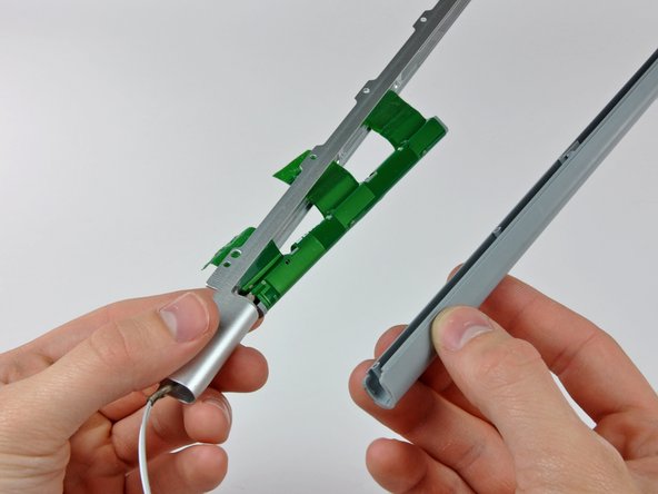
Step 36

– Gently coax those antenna cables away from the clutch cover, watching out for sneaky connectors that might try to hitch a ride!
Step 37

– The clutch cover stays on.

