
DIY MacBook Pro 15 Heat Sink Replacement Guide
Duration: 45 minutes
Steps: 22 Steps
Hey there! Just a quick heads-up: make sure to double-check everything before diving in. If you hit a snag or feel out of your depth, don’t hesitate to schedule a repair. We’ve got your back!
The heat sink is like the chill pill for your processor, keeping it cool and content.


Step 2


– Unscrew those three identical 2mm Phillips screws holding the memory door in place. You’ve got this!
– Gently lift the memory door just enough to get a good grip, then slide it towards you to pop it off the casing. Easy peasy!
Step 3

– Pop out the two 2.8 mm Phillips screws in the battery compartment near the latch. If you need help, you can always schedule a repair
Step 4

– Time to jazz up the party with screw removal! Get ready to say goodbye to 6 screws:
Step 5

– Time to unleash your inner repair ninja and bid farewell to those four pesky 3.2 mm PH00 Phillips screws chilling on the port side of the computer!
Step 6

– Give your computer a nifty 90-degree twist and pop out those two 3.2 mm Phillips screws from the back. If you need help, you can always schedule a repair.
Step 7

– Give your computer a little twist and turn it 90 degrees once more! Now, let’s tackle those four 3.2 mm Phillips screws on the side. Time to show them who’s boss!
Step 8


Hey, take it easy when removing the upper case! It’s linked to the logic board by a ribbon cable. If you need help, you can always schedule a repair.
– Alrighty! Lift up at the rear of the case and work your fingers along the sides like a pro, freeing the case as you go. Once the sides are free, you might need to rock the case up and down a bit to loosen the front of the upper case.
– Here’s the deal: There are four plastic clips above the DVD slot, and another one above and to the left of the IR sensor. These clips can be a bit tricky to disengage without some gentle prying. Putting them back during reassembly can also be a bit challenging.
– Pro Tip for Reassembly: Firmly press down on the tip of the top case above each clip location until you hear a satisfying snap to secure them in place.
– Pro Tip for Reassembly: The two center DVD clips might need a little extra help to snap back into place properly. Instead of just applying pressure and risking frame deformation, support the frame by gently inserting a plastic spudger into the DVD slot directly beneath the clip location until it fits snugly. Then, press down until you hear that satisfying snap.
Tools Used

Step 9


Just a heads-up: You can totally swap out the hard drive without unplugging the keyboard from the chassis. Just make sure to keep it propped up out of your way so you can work your magic with both hands on that drive removal!
Take your time when you’re detaching the keyboard-trackpad ribbon cable. Make sure the rear of the upper case is clear from the hinge area. It’s super easy to accidentally bend the screw receivers on either side of the keyboard, so go slow and steady!
– Time to party with your repair—start by saying see ya later to the trackpad and keyboard ribbon cable from the logic board, removing tape as needed.
– Now, give the upper case a little lift and send it on its way.
Step 10

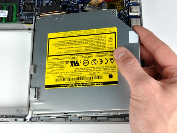
– Grab your trusty spudger and gently pry off the orange SuperDrive ribbon cable from the logic board. Don’t forget to peel away any tape that’s holding it down. You’ve got this!
Tools Used

Step 12

– Unplug the hard drive and ExpressCard connectors from the left side of the logic board. If you need help, you can always schedule a repair
Step 13

– Gently disconnect the iSight and display data cables from the logic board by sliding them straight back out of their connectors, and feel free to remove any tape if needed.
Step 14

Handle those tiny connectors with care! A little too much enthusiasm with the spudger might just send them flying off the logic board. Let’s keep everything intact!
– Pop off those eight connectors by sliding a spudger under the wired side and lifting up. Easy does it! If you need help, you can always schedule a repair.
Tools Used

Step 16

– Get ready to say goodbye to the silver 9.5 mm T6 Torx screw that’s keeping the ground loop in the display data cable snugly attached to the casing.
Step 17

– Pop out that single black 6 mm T6 Torx screw holding the upper part of the logic board to the lower case.
Step 18

– Now it’s time to peel back the cool orange Kapton tape that’s keeping the right thermal sensor cable safe and snug on the logic board.
Step 19

– Alright, let’s get to it! Start by taking out these 15 screws:
Step 20

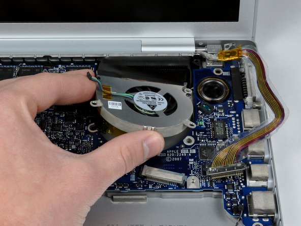
Go ahead and position the left fan right above the Airport card. You don’t have to take the fan completely out of the device. If you need assistance, feel free to schedule a repair.
– With one hand, keep the logic board steady while your other hand lifts the left fan out of its cozy spot. There’s a sneaky piece of black tape holding the left fan to the heat sink—gently peel it away as you lift the fan up.
– Now, give the right fan a little lift and carefully peel off the tape that’s keeping it snug against the heat sink.
– Once you’ve done that, go ahead and remove the right fan from the computer.
Step 21


– Gently lift the left side of the logic board and unplug the gray and black power cable from the bottom. Easy peasy!
– Hold onto the logic board at the left side and the thin section, then give it a little twist to pop it out of the lower case. You’ve got this!
– If you removed the heatsink from the motherboard earlier, it’s time to clean off that old thermal compound from the chips on the back of the logic board. Check out our Applying Thermal Paste Guide to get those processor and heat sink surfaces ready for action!
Step 22

Need to reattach the heat sink? No sweat! Check out our thermal paste guide to slap that thermal compound on like a pro.
– Carefully hoist the heat sink out of your computer like it’s a treasure chest!
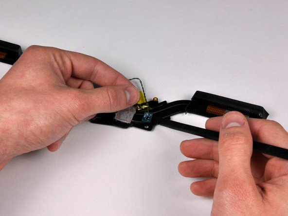
– Peel back the orange Kapton tape to unveil the secret thermal sensor beneath.
– Use a spudger to gently persuade the middle thermal sensor to detach from the heat sink.
– Voila! The heat sink is free!
Tools Used


