
DIY MacBook Pro 15 Left I/O Board Cable Replacement Guide
Duration: 45 minutes
Steps: 28 Steps
Hey there, awesome fixer! Just a heads-up, remember to handle your device with care and keep those repair vibes positive!
This hooks up the left I/O board to the logic board. If you need help, you can always schedule a repair
Step 2

– Unscrew the three matching Phillips screws from the memory door. You’ve got this!
– Don’t forget to keep track of which screws go where. It’ll make putting everything back together a breeze!
Step 3

– Gently lift the memory door just enough to get a good grip, then slide it towards you to pop it away from the casing. You’ve got this!

Step 5

– Let’s get those 6 screws out of the way!
Step 6

– Unscrew the four Phillips screws chillin’ on the port side of your device.
Step 7

– Give your computer a little twist and turn it 90 degrees! Next, grab your trusty Phillips screwdriver and remove those two screws hanging out on the back. You’ve got this!
Step 8

– Give your computer a little twist and turn it 90 degrees once more. Now, let’s tackle those four Phillips screws on the side and get them out of the way!
Step 9

Hold your horses! Don’t just rip off the upper case like a band-aid. It’s still connected to the logic board with a sneaky little ribbon cable. Take it slow, superstar!
– Start by lifting the back of the case and wiggle your fingers along the edges to loosen it up. Keep going until the sides are free. You might have to give the case a little jiggle to release the front part of the upper case—this bit can be a bit of a puzzle! Watch out for the four sneaky tabs above the DVD reader that need to be pulled out straight up.
– Heads up! The two tiny tabs on the front left of the upper case might get a bit bent out of shape during removal. No worries, though! Just give them a little tweak to slot them back into the grooves of the lower case when you’re putting things back together.
Step 10

– Unhook the trackpad and keyboard ribbon cable from the logic board, peeling off any tape if needed.
– Eject the upper case.

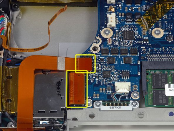
Step 12

– Grab your spudger and perform a little magic trick! Flip up the brown plastic flap that’s keeping the left ambient light sensor cable cozy on the logic board.
– Gently slide the left ambient light sensor cable to the left and wiggle it out of its connector like you’re pulling a rabbit out of a hat!
Tools Used

Step 13

– Unstick the left ambient light sensor cable from atop the left fan. Let’s keep it cool and breezy!
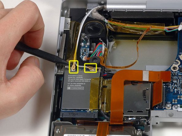
Step 14

– Gently lift and detach the iSight and inverter cables from above the left fan. Feel free to remove any tape that’s getting in your way as you go!
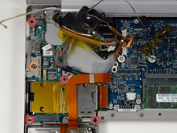
Step 15

– Unscrew the following 3 amigos:

Step 17
– Unplug the hard drive and ExpressCard connectors from the left side of the logic board, amigo!
Step 18
– Unplug the two antenna cables hooked up to the Airport Extreme card.
– The white antenna cable connects to the left side of the Airport Extreme card.
Step 19
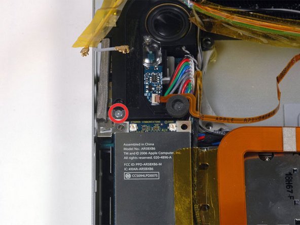
– Let’s get started! First up, take out the shiny silver Phillips screw that’s hanging out just above the Airport Extreme card.
– Now, gently lift the small silver metal retaining bracket out of the computer. You’ve got this!
Step 20
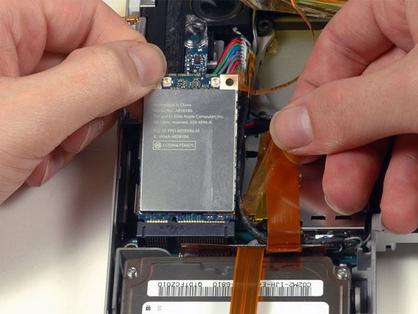
– Carefully peel back the funky orange tape on the right side of the Airport Extreme card.
– Give the Airport Extreme card a little lift and gently slide it out of its connector.
Step 21
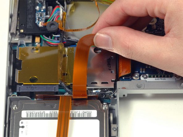
– Gently lift the orange hard drive cable away from the ExpressCard cage, like you’re peeling a banana—easy does it!
Step 22
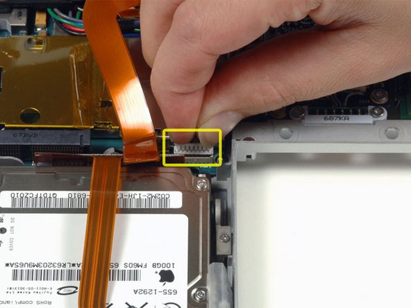
– Unplug that speaker cable from the corner of the left I/O board.
Step 23
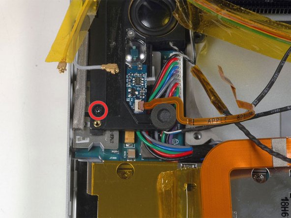
– Unscrew the single black T6 Torx screw that’s holding the left speaker in place.
Step 24
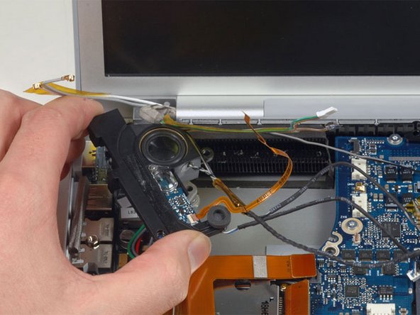
– Hoist the left speaker assembly from its cozy nook and plop it down where the left fan used to chill.
Step 25
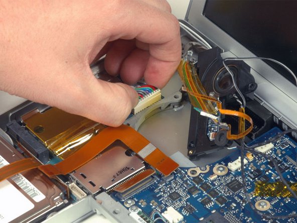
– Unplug that snazzy, rainbow-like power cable from the left I/O board.
Step 27
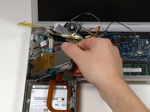
– Give the right side of the left I/O board a gentle lift and smoothly slide it out of the computer.
Step 28
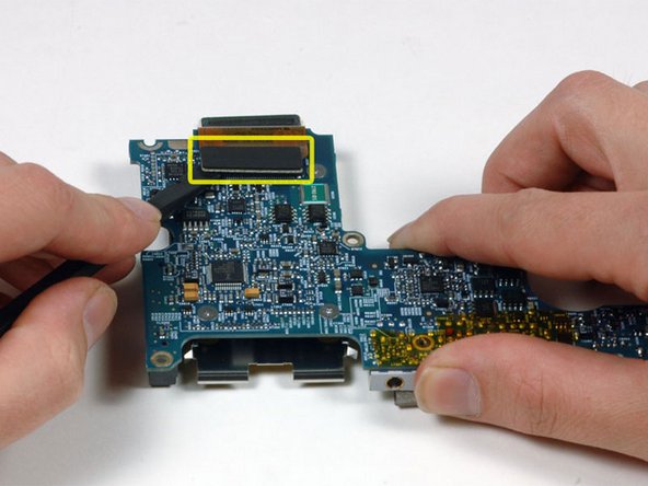
– Flip the left I/O board over and unplug that short left I/O board cable like a pro!


