DIY Microsoft Surface Laptop 3 (15-inch) Battery Replacement Guide
Duration: 45 minutes
Steps: 49 Steps
For your own safety, make sure to let that battery dip below 25% before diving into your laptop disassembly adventure!
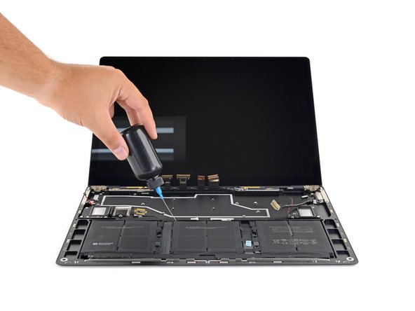
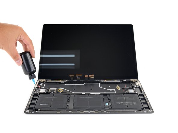
Ready to swap out that tired or lifeless battery on your Microsoft Surface Laptop 3 (15″)? Let’s do this! First things first—keep things safe and simple. Make sure your battery is drained below 25% before starting, so there’s less risk of any fiery surprises if things get bumped. Got a puffed-up, swollen battery? Handle it with care, like it’s made of glass. Oh, and don’t forget—you’ll need some sticky stuff, like Tesa 61395 double-sided tape, to secure the new battery in place. Let’s get this laptop back to being its best self!
Step 1


– First things first, let’s give your laptop a little break—power it down and unplug all those pesky cables.
– Now, gently close the laptop like you’re tucking it in for a cozy nap.
Step 2


– Turn your laptop upside down and set it on your workspace with the feet pointing up.
Step 3


To get those feet off the bottom of your laptop, grab a spudger and use the pointed end—it’s the perfect tool for the job!
Just a heads-up: the two feet at the back (closer to the screen) are a bit different from the two at the front, so pay attention!
– Let’s get started with removing those feet – each one has a sneaky little indent that makes it a breeze to take out.
– To ensure your spudger is in the right spot, slide it in at the nearest long edge and push it parallel to the short edges of your laptop, just like the picture shows. Easy peasy!
Tools Used

Step 4


The two rear feet are held in place with a bit of light adhesive magic.
– Start by sliding the pointy end of your spudger under one of the rear feet, right at the back edge.
– Gently push the spudger underneath and pry it up to detach the foot.
– Now do the same for the second rear foot to free it up!
Tools Used
Step 5


The two front feet are held in place by plastic clips and a bit of gentle adhesive, making them easy to remove and replace.
– Slide the sharp end of your trusty spudger under one of the two front feet, right at the edge.
– Gently push the spudger beneath the foot and lift it up to pop it free.
– Now, do the same for the second front foot and you’re on your way!
Tools Used
Step 6


– As you’re putting everything back together, keep in mind that the front and rear feet are not the same. They’re unique, so don’t mix them up!
– The front feet have a specific direction, so they’ll only clip in one way. Just pay attention to the direction and it’ll click right in.
Step 7


– Instead of reusing those old, beat-up feet on your device, you can use 8 mm rubber furniture pads—they work great!
– Just peel a pad from its backing, line it up over the foot cavity, and press down to make it stick. Easy peasy!
Step 8

Throughout this repair, keep an eagle eye on each tiny screw. To avoid any laptop mishaps, make sure each one goes back to its original home. If you need help, you can always schedule a repair
– Grab your trusty T5 Torx driver and gently remove the four 3 mm screws hiding in the foot cavities. These little guys hold the upper case to the device, so keep them safe!
– When putting it all back together, remember these screws are delicate little flowers—don’t over-tighten them, or they might strip. Nobody wants that! If you need help, you can always schedule a repair
Step 9


– Turn the device over so the bottom faces up.
– Open the display all the way until it’s fully extended.
Step 10


Hold up—don’t yank that upper case off just yet! It’s still tethered to the laptop, so take it easy.
Make sure the upper case hugs the whole perimeter snugly. Any gaps near the display could spell trouble for your screen when it closes, and nobody wants that.
Magnets hold the upper case in place, how cool is that?
– Grab the top edge of the upper case above the keyboard and give it a steady lift straight up to pop it loose.
– Carefully tilt the front edge of the upper case upward and away from the laptop, being mindful not to tug on the keyboard and touchpad ribbon cable underneath.
– When putting it all back together, gently lower the upper case onto the lower case until the magnets snap into place and it sits nice and flat.
Step 11


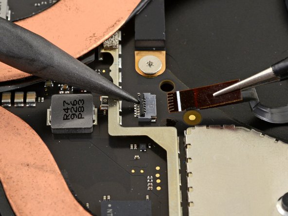
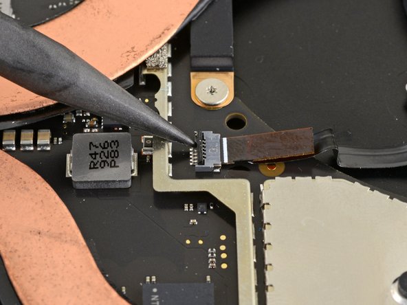
The ribbon cable for the keyboard and touchpad is kept snugly in place by a magnetic connector.
Some models might have this connector wrapped in black tape—just a heads-up!
– Gently slip the flat end of a spudger under one side of the ribbon cable connector and give it a nudge to pop it free.
– Carefully detach the ribbon cable from the motherboard—it’s like unplugging a tiny seatbelt!
Tools Used
Step 12


Make sure that ribbon cable is smooth, flat, and happy – not all twisted or strained. Lay it out nicely to avoid any potential damage or stress.
– Pop off that upper case like a pro.
– Flip it over and lay it down gently on a clean surface, keyboard side facing down.
Step 13

Taking out the SSD is like hitting the pause button on your battery – it’s a must-do before diving into any major repairs. Let’s keep things safe and smooth!
– Grab your T5 Torx driver and remove the 2.7mm screw that’s holding the SSD in place. Nice and easy, you’ve got this!
Step 14


Once you’ve taken out the SSD screw, watch as the SSD gracefully lifts up at a slight angle, ready for its next adventure!
– Grab the SSD’s end like you’re holding a tiny surfboard, and gently yank it out of its connector-thingy on the board. It’s like pulling a tiny, super-important tooth!
– When you’re putting things back together, slide the SSD into its connector at a chill, low angle. Then, flatten it out and secure it with the SSD screw. Think of it like tucking a tiny, data-filled surfboard back into its case.
Step 15


– Grab your trusty tweezers and carefully peel off those two sneaky pieces of black tape hiding in the bottom left and bottom right corners of the motherboard.
– When putting things back together, if that tape’s still got some stick to it, go ahead and reuse it!
Tools Used

Step 16


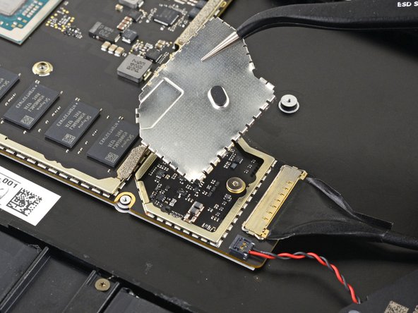
Be gentle with that shield—it’s going to make a comeback during reassembly, so try not to bend or deform it too much!
– Grab your opening tool and gently pry up the front edge of the metal shield. It’s like sneaking into a secret lair, but for heatsinks!
Step 17


– Gently dance your way around the edge of the shield, popping it up here and there, until you can lift that bad boy off completely. If you need help, you can always schedule a repair
Step 18


– Go ahead and take off that heatsink shield!

Step 20

– Grab your trusty T3 Torx driver and let’s get those heatsink screws out of the way. Here’s the lineup:
– • Two 2.5 mm screws—tiny but mighty!
– • Three 2.0 mm screws—teamwork makes the dream work.
– • One 3.0 mm screw—standing solo, but important.
– • Two 4.1 mm screws—big players in the game.
– • Two 3.4 mm screws—holding it all together.
Step 21

– Time to put it all back together!
– Carefully position the heatsink so it lines up with the centering peg on the motherboard – easy does it!
– Tighten those four CPU tension screws in an ‘X’ pattern – nice and snug, but not too tight!
Step 22


– Gently use your fingertip to lift the right edge of the heatsink off that little alignment peg by the fan on the bottom case. We’re almost there!
– Once you’ve freed the heatsink from the peg, give it a gentle tug towards the front of your device. You’re doing great!
Step 23


Be gentle with the heatsink; those heat pipes can be a bit delicate and might get bent if you’re too rough.
If the heatsink seems to be playing hard to get with the CPU, give it a gentle wiggle from side to side to help it break free from the thermal paste that’s keeping it snug.
– Take off the heatsink with care.
Tools Used

Step 24


– Before putting the heatsink back on, give it and the CPU a good clean, then slap on some fresh thermal paste. Keep it cool, keep it smooth—your device will thank you!
Tools Used
Step 25

Some motherboard screws are tucked under two metal shields, so you’ll need to pop those off.
Be gentle with the shield—you’ll need it back in tip-top shape for reassembly.
– Grab your trusty opening tool and gently nudge up one edge of the metal shield hanging out on the right side of the motherboard.
– Work your way around the shield like a pro, prying here and there until it’s loose enough to lift off completely.
– And just like that—off goes the shield!
Step 26


– Follow the previous step again to remove the second shield from the left side of the motherboard, right next to the CPU. You’ve got this!
Step 27
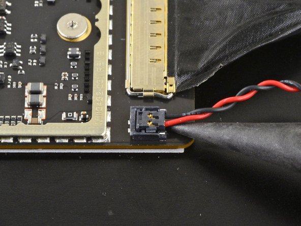
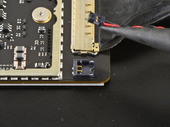

– Grab the pointy end of your trusty spudger and gently pop the right speaker wire out of its connector on the motherboard. Easy peasy!
Tools Used
Step 28


– Grab your trusty opening tool and pop open the gold locking arm on the Surface Connect port’s motherboard connector.
Step 29


– Gently grab the Surface Connect port cable and give it a nice, confident pull to pop it out of its connector. Easy does it!
Step 30


– Gently use the pointed end of a spudger to carefully lift and disconnect the left speaker wire from its cozy little connector on the motherboard. You’ve got this!
Tools Used
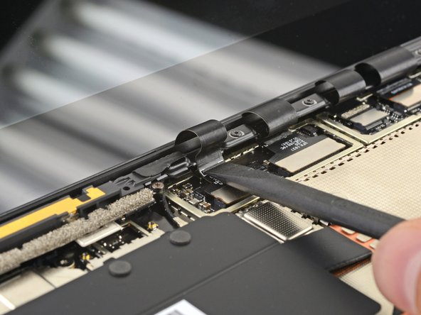
Step 31


Be gentle with the shield—it’s going to be your buddy during the reassembly, so let’s keep it in shape!
– Grab your trusty opening tool and gently wiggle it to lift the black shield that’s guarding those display connectors on the right side.
– Keep at it around the edges until the shield starts to feel a bit more relaxed.
– Once it’s loose enough, go ahead and lift that shield off!
Step 32


– Do it again! Just like before, lift off the last shield from the left side of those display connectors. You’re doing great!
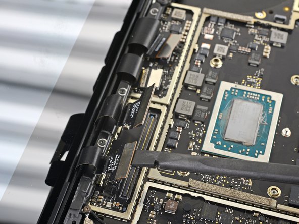
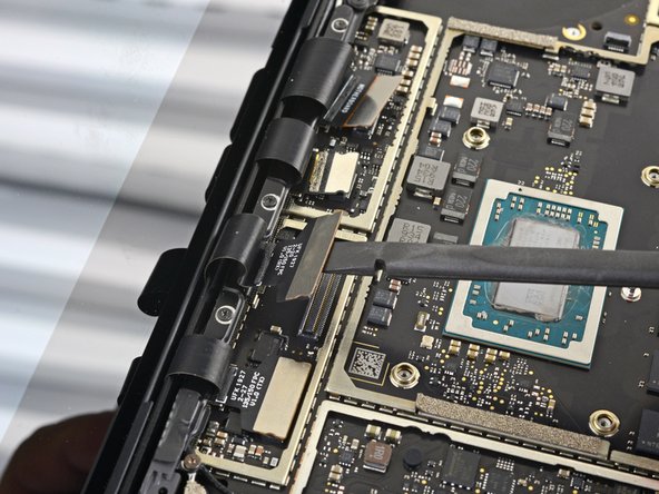
Step 33


– Grab your trusty spudger and gently slide the flat end under the first display cable. Give it a little lift to pop it out of its cozy socket on the motherboard. Easy peasy!
Tools Used


Step 37

– Grab your trusty T3 Torx driver and let’s tackle those two 3 mm screws holding the motherboard bracket in place. You’ve got this!
Step 38

– Time to get up close and personal with those tiny parts! Use a trusty pair of tweezers to carefully remove the motherboard bracket – you got this!
Tools Used
Step 39


– Grab your T3 Torx driver and pop out those six 2mm screws holding down the motherboard.
– For an easier motherboard removal, use your T3 Torx driver to take out the three screws holding the port bracket, and then lift off the bracket.
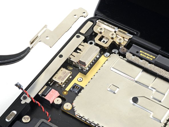
Step 40


Keep track of those two screwpost braces under the motherboard while you’re removing it, so they don’t get lost.
If the motherboard seems a bit snug, just slide it to the right to free up the I/O ports from their cutouts on the chassis.
– Gently wiggle your fingers to lift and pop out the motherboard.
Step 41

– While reinstalling the motherboard, make sure no cables get stuck under it as you lower it into place. Double-check these five spots:
– Four display cables
– Antenna cable
– Left speaker cable
– Surface Connect cable
– Right speaker cable
Step 42
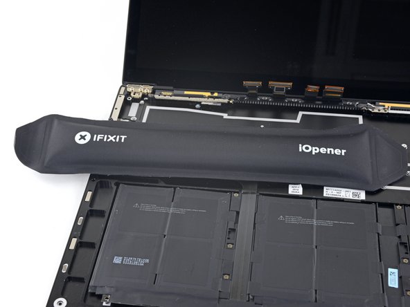

No iOpener? No problem! Grab a hair dryer and give that cable a little warm-up.
– Warm up your iOpener and place it on top of the battery contact cable for about a minute. This’ll loosen up the adhesive holding it down. Ready, set, peel!
Tools Used

Step 43

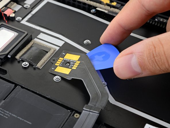
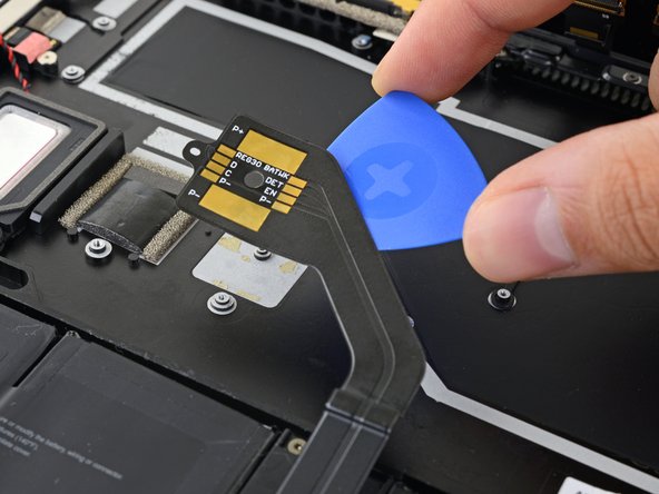
If the adhesive is being a bit too clingy, don’t stress the pick! Just give the cable a gentle reheat and give it another go.
– Gently slide an opening pick under the battery contact cable to release it from the case. You’re doing great!
– As you put things back together, remember that the contact cable is snugly positioned with both a screw post and an alignment peg. You’ve got this!
Step 44

– Grab your trusty T3 Torx driver and get ready to tackle those six 2.7 mm screws holding the battery snug in place. You’ve got this!