DIY Samsung Galaxy S III Front Panel Assembly Replacement Guide
Duration: 45 minutes
Steps: 38 Steps
Heads up, champ! Make sure you’re in a well-lit area and have all your tools ready. It’s time to bring your device back to life!
Follow this snazzy guide to swap out the front panel assembly. It’s like giving your device a fresh new face!
Step 1


You can totally nail the next four steps without a plastic opening tool, but hey, why risk it? Using one might just keep those pesky clips on the rear case from snapping. Keep things chill and clip-friendly!
– Wedge a plastic opening tool or your trusty fingernail into the little notch at the top of your phone—right where the back case meets the phone body.
– Give that opening tool a gentle twist to pop open the clips holding the rear case’s top edge in place. Feels like unlocking a treasure chest, doesn’t it?
Step 2


– Scoot your plastic opening tool to the left along the top edge and give it another twist to make that gap between the rear case and the phone a bit roomier.
Step 3


– Keep cruising with that plastic opening tool around the top left corner’s edge. Just give it a gentle lift and pry along the back case. Keep it cool and easy!
Step 4


– Wiggle your pry tool along the top right edge and shimmy it down the right side of the rear case. Keep the groove going!
Step 5


You might have to play a little tug-of-war to free the case from any sneaky clips still clinging to the phone’s bottom. Keep at it, champ!
– Hoist that rear case off your phone and set it aside, champ!
Step 6


– No fancy tools needed for this step! Feel free to use your finger to get things rolling.
– Pop a plastic opening tool into the tiny notch right above the battery. It’s like unlocking a little treasure chest!
– Give that battery a gentle nudge upwards with the tool and voila, it’s out of its hidey-hole!


Step 8


– Gently push the SIM card a tad deeper into its slot with your fingernail until you hear a satisfying click.
– Once you hear that click, let go and watch the card spring out of its slot like magic.
– When putting it back together, just press the SIM card back into its slot until you feel that reassuring click.
Step 9


– Give that SIM card a gentle nudge with your thumb to slide it out just enough to get a good grip on it.
– Snag that little escape artist of a SIM card and lift it right out of its cozy slot.
Step 10


– Nudge your microSD card a smidge further into its cozy slot using your fingernail, until you hear a satisfying click.
– Once you hear that click, let go of the card and watch it spring out like a tiny jack-in-the-box!
– When putting it back together, just press the microSD card back into its home until you feel that click to know it’s snug and secure.
Step 11


– Slide the microSD card out of its slot using your thumb.
– Take the microSD card out of the phone.
Step 12

– Unscrew the ten 4.0 mm Phillips screws that are holding the midframe cozy against the front panel assembly.
Step 13


The midframe just gives a little click and pops off effortlessly—like magic, but you’ve got this!
– Grab the left side of the plastic midframe with your thumb and forefinger, and give it a gentle lift away from the phone. It’s like lifting the lid off a cookie jar—easy peasy!
Step 14


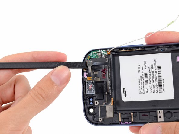
Hey there, make sure you’re prying on the connector itself, not the socket—no one wants a sad motherboard!
– Grab a plastic opening tool and give the rear-facing camera connector a gentle nudge out of its cozy spot on the motherboard.
Step 15


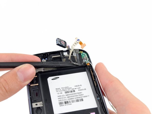
– Slide your plastic opening tool just outside the speaker area of the headphone jack/speaker combo.
– With a gentle touch, lever up the headphone jack/speaker unit from the main assembly.
Step 16

– Hoist the snazzy headphone jack/speaker ensemble right out of your Galaxy S III. You got this!
Step 17

Hold your horses! Don’t yank out the front-facing camera just yet. The sneaky little cable is still playing hide and seek under the motherboard, all the way to the ambient light sensor.
– Grab your plastic opening tool and gently pop the front-facing camera connector out of its cozy spot on the motherboard.
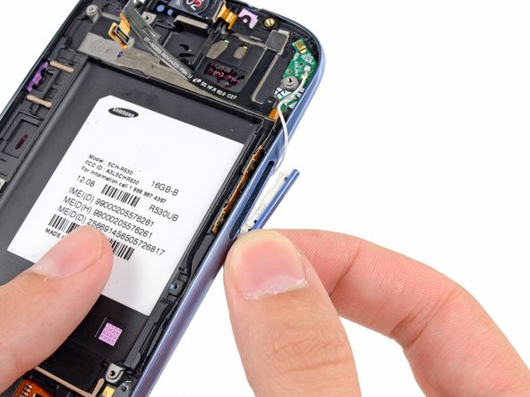
Step 18


– Gently lift the connector of the digitizer cable from its cozy home on the motherboard. Just give it a little pry-up, and voilà!


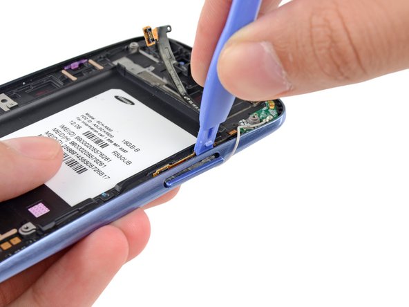
Step 20


– Pop the Wi-Fi antenna cable connector off its cozy little home on the motherboard with a gentle pry.
– Scootch the cable aside to clear the stage for motherboard shenanigans.
Step 21

– Unscrew that lonely 3.0 mm Phillips screw that’s holding the motherboard to the front panel assembly. Just one little twist and you’re on your way to tech wizardry!
Step 22


– Gently hoist the bottom end of the motherboard assembly away from the front panel assembly like you’re lifting a slice of pizza.
– Ease the motherboard assembly out of the front panel assembly, being mindful of any sneaky cables that might catch on it.
Step 23

– Unscrew the lone 2.0 mm Phillips screw that’s keeping the front-facing camera bracket in its cozy spot on the front panel.
Step 24


– Grab your tweezers and gently hoist the front-facing camera combo (that’s the camera, ambient light sensor, and rear mic) right out of its cozy nook in the front panel assembly. Easy does it!
Tools Used

Step 25


Hold up! Don’t pull the antenna cable all the way out just yet—it’s still hooked up to the antenna board!
– Gently lift the antenna cable out of its groove on the front panel assembly.
Step 26


– Slide the trusty spudger under the earpiece speaker and give it a little nudge to pop that speaker right out of its cozy nook in the front panel assembly.
Step 27

– Grab your trusty spudger and use its flat edge to gently lift the top part of the earpiece/volume buttons/ambient light sensor ribbon cable away from the front panel assembly. It’s like peeling a sticker, but way cooler!
Step 28

– Gently slide the flat edge of a spudger under the ambient light sensor like a ninja.
– Keep on rocking and peel the earpiece/volume buttons/ambient light sensor ribbon cable off the front panel assembly.
Step 29

– Slide the flat edge of a spudger gently under the connector for the earpiece, volume buttons, and ambient light sensor ribbon cable.
– Carefully glide the spudger across to peel away the earpiece, volume buttons, and ambient light sensor ribbon cable from the front panel assembly.
Step 30

– Wedge a plastic opening tool between the ribbon cable of the buttons and the volume button itself. It’s like coaxing a cat out from under the bed—gently does it!
– Give the volume button a nudge to pop it out of its cozy nook in the front panel assembly. It’s a little shy, but a firm push will do the trick!
– Carefully lift and remove the volume button from its home in the phone. Voila! You did it!
Step 31


– Slide the flat edge of a plastic opening tool between the earpiece/buttons/ambient light sensor ribbon cable, and gently glide it along to weaken the sticky adhesive. It’s like buttering toast, but way cooler because you’re fixing tech!
Step 32

– Grab and gently pull out the earpiece/buttons/ambient light sensor ribbon cable from the phone. You got this!