DIY Samsung Galaxy S20 Motherboard Replacement Guide
Duration: 45 minutes
Steps: 36 Steps
Hey there! Just a friendly reminder to take your time and be gentle with your device during this repair. If you run into any trouble, don’t hesitate to reach out for some assistance. You can always schedule a repair with us!
Ready to dive into the world of phone repairs? This guide will help you swap out the motherboard in your Galaxy S20 like a pro! Just a heads up, you’ll want to grab some replacement adhesive to wrap things up nicely. If you need help, you can always schedule a repair.
Step 1


– Got a SIM card eject tool, bit, or a paperclip? Great! Pop that buddy into the hole on the SIM tray, which you can find chilling at the top edge of your phone next to the plastic antenna band.
– Gently give it a firm press to gracefully eject the tray. Smooth moves!
Tools Used

Step 2


– First up, let’s get that SIM card tray out of there! Give it a gentle pull.
– When it’s time to pop that SIM card back in, make sure it’s snug in the right way according to the tray. No twisting or turning!
– Oh, and don’t forget about that little rubber gasket around the SIM tray! It’s your phone’s superhero against water and dust. If it’s looking a bit worn or missing, it’s a good idea to swap it out or replace the whole SIM tray to keep your phone’s insides safe and sound.
Step 3

Make sure to unplug and switch off your phone before diving in!
– Get your iOpener nice and toasty, then gently press it against the lower edge of the back cover for a couple of minutes.
Tools Used

Step 4


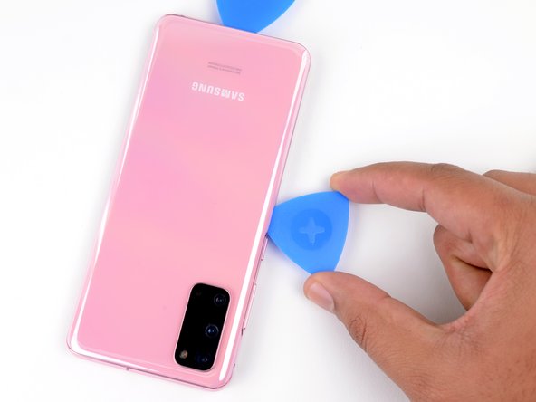
– Get that suction cup ready in position, right at the center of the bottom edge.
– Give that suction cup a firm tug, applying consistent force to make some space between the back cover and the frame.
– Slide an opening pick into that gap like a champ.
Step 5


– Glide the pick back and forth along the bottom edge to effortlessly cut through the adhesive.
– Pop in your opening pick in the seam to make sure the adhesive doesn’t sneakily stick back together.
Step 6

– Warm up a heated iOpener and place it along the left edge of the back cover for a solid two minutes. You’ll want to give it a nice, cozy hug of heat to help loosen things up!
Tools Used
Step 7


Handle that pick with care—too much pressure could lead to a shattered back cover glass!
Don’t fret if it takes a few tries due to the snug fit.
– Start by placing a suction cup on the back of the phone, aiming for the center of the left edge. Let’s get that grip!
– Give the suction cup a strong, steady pull to create a little space between the back cover and the frame. You’re doing great!
– Next, gently slide the tip of an opening pick into that gap you’ve created. Keep it steady!
Step 8


– Alright, buddy, with the pick on the edge, give it a gentle tilt downwards and work it under the glass a bit more to completely break that back cover’s sticky bond!
Step 9


– Alrighty, fellow tech wizards! Time to embark on a fantastic quest to save your device. Slip that nifty pick along the left side of your phone to break the back cover’s sticky bond, and keep your trusty tool at the top left corner to stop the seal from mending itself. If you need help, you can always schedule a repair!
Step 10

– Warm up that iOpener and give it a cozy two-minute hug on the right edge of the back cover.
Tools Used
Step 11


– Get ready to get the show on the road by slapping a suction cup on the back of your device, right smack in the middle of the right edge.
– Give that suction cup a solid tug with some gusto to make way for a sweet gap between the back cover and the frame.
– Time to bring in the opening pick! Slide that bad boy right into the gap you just created like a pro.
Step 12


– Gently glide the pick along the right edge of the phone to release the back cover’s adhesive.
– Keep the pick snug under the right edge of the glass near the top of the device to prevent the adhesive from sticking back.
Step 13

– Warm up that iOpener and give the top edge of the back cover a cozy two-minute embrace.
Tools Used
Step 14


The glass around the corners of the back cover is a bit of a drama queen and loves to crack if you’re not careful. So, take it easy during this step to keep your back cover looking fabulous!
– Let’s smoothly glide the pick along the right edge of your device, making our way to the top right corner with style.
– Next, let’s continue our slicing adventure along the top edge until we reach the top left corner. Our mission? To completely separate that back cover adhesive!
Step 15


– Gently lift off the back cover like you’re peeling a banana, and don’t forget to use those trusty opening picks to cut through any stubborn adhesive that’s still hanging on.
– Now, go ahead and take off the back cover completely.
– As you put everything back together, remember to keep it cool and collected!
Step 16

– Grab your trusty Phillips #00 screwdriver and remove those five 4 mm-long screws holding the motherboard bracket in place. You’ve got this!
Tools Used

Step 17


– Get those tweezers ready and give that motherboard bracket a gentle tug to unclip it from the plastic midframe.
Tools Used

Step 18


– Carefully peel the wireless charging coil away from the device—think of it as gently coaxing a shy friend to come out and play.
– Remove the wireless charging coil with confidence; it’s time for a little makeover!
– As you put everything back together, start by securing the motherboard bracket screws first. This will help you line up the charging coil just right. Once it’s in place, give the rest of the coil a solid press to make sure it sticks like a champ.


Step 20

– Grab your trusty Phillips #00 screwdriver and get ready to work some magic! Start by unscrewing the five 4 mm-long screws that are holding the loudspeaker and lower midframe in place. You got this!
Tools Used


Step 22

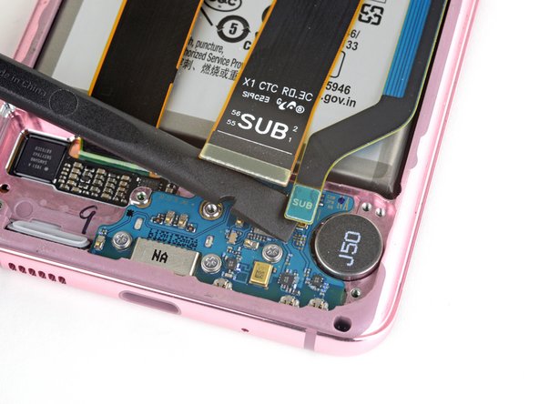
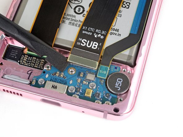
– Got a spudger? Great! Use it to gently lift and disconnect the main and auxiliary flex cables from the daughterboard located near the lower end of your device. You’ve got this!
– Ready to re-attach those press connectors? Awesome! Make sure to align them carefully and press down gently on one side until you hear that satisfying click. Then, repeat on the other side – easy does it! Avoid pressing down on the center to prevent any mishaps. Keep those pins in shape and prevent any permanent damages. Way to go!
Tools Used
Step 23

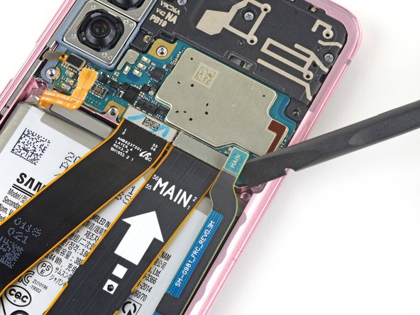

– Grab your trusty spudger, and gently pry up to separate the main and auxiliary flex cables from the motherboard. You’ve got this!
Tools Used


Step 25


– Grab a spudger and gently work your magic to lift and disconnect the main display flex cable from the motherboard. You’ve got this!
Tools Used
Step 26


– Gently lift and gently maneuver the display flex cable away from the motherboard and battery with care.
Step 27

– Grab your trusty Phillips #00 screwdriver and let’s get to work! Carefully unscrew the four 4 mm-long screws that are keeping the upper midframe snug and secure. You’ve got this!
Tools Used


Step 29


– Grab your trusty spudger and gently nudge the side button flex cable away from the motherboard. It’s like giving it a little hug to help it disconnect!
– Next, take a pair of tweezers and carefully bend the cable out of the motherboard’s way. Think of it as helping the cable take a scenic route!
Step 30


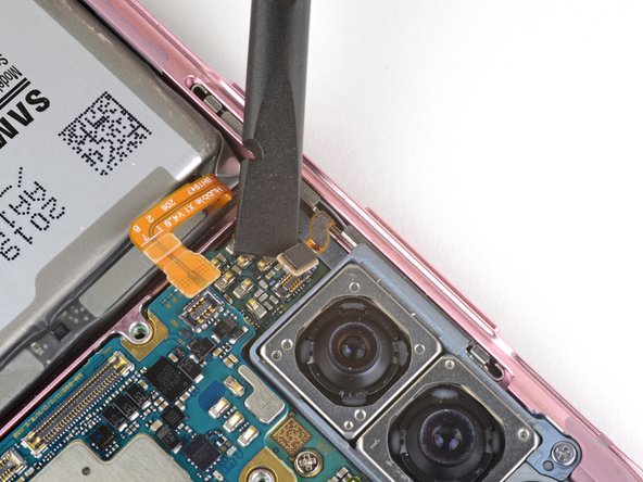
– Gently lift and unplug the front-facing camera flex cable from the motherboard. You’ve got this!
– Carefully bend the cable out of the way so it doesn’t get in the motherboard’s business.
Step 31

– Gently lift and disconnect the snazzy front-facing sensor array cable from its cozy spot on the motherboard.
– Swoosh the cable out of the way, giving the motherboard some breathing room.
Step 32

– Let’s have some fun with our #00 Phillips screwdriver! Detach the motherboard and camera buddies with just a couple spins counterclockwise. Need a hand? Give our repair squad a shout at schedule a repair
Tools Used
Step 33
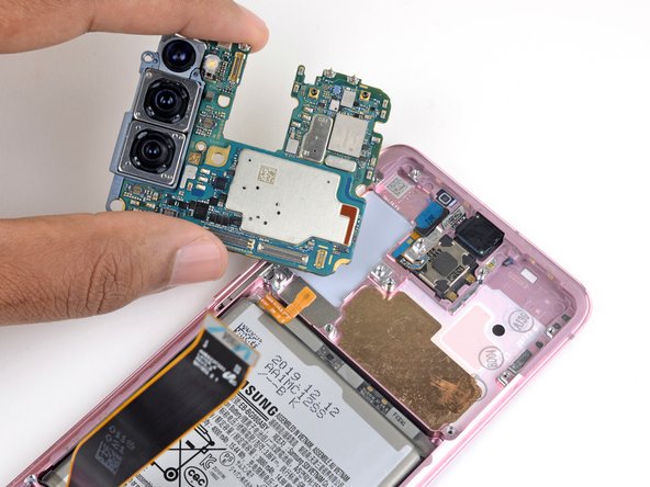

– Gently slide the flat end of your trusty spudger into the bottom left corner of the motherboard assembly and give it a little nudge to pop it free from the phone’s body.
– Now, go ahead and lift out the motherboard assembly with care!
Tools Used
Step 34

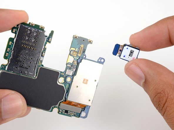
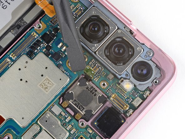
– Grab that trusty spudger and gently wiggle it to pop up the ultrawide camera connector from the motherboard. It’s like giving it a little high-five!
– Now, go ahead and lift out the ultrawide camera module. You’re making great progress!
Tools Used
Step 35

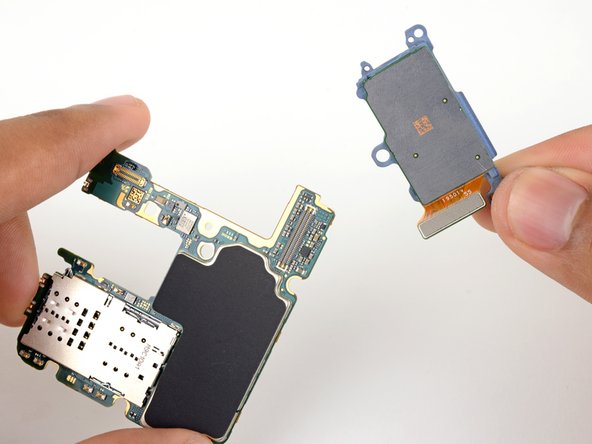
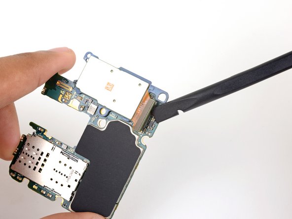
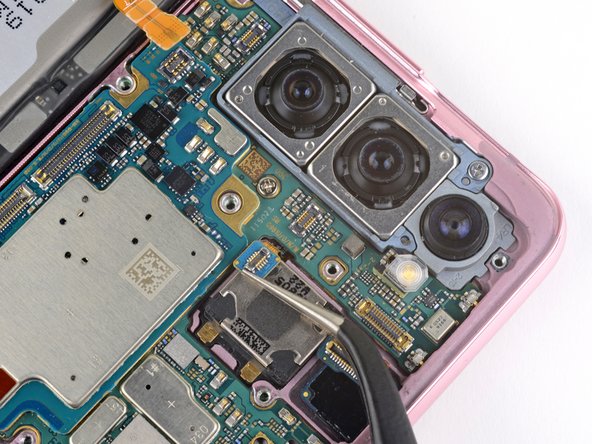
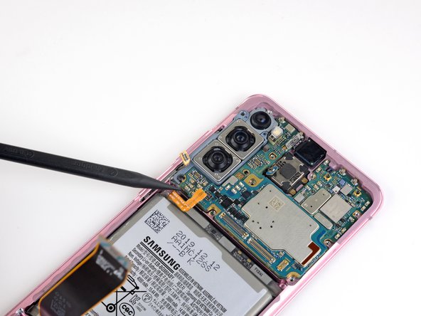
– Grab your trusty spudger and gently pry up that telephoto and wide-angle camera connector from the motherboard. It’s like giving your phone a little nudge to say, ‘Let’s do this!’
– Now, go ahead and remove the last rear-facing camera module. You’re almost there!
Tools Used
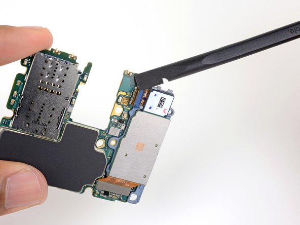
Step 36

– Hooray! You’ve reached the motherboard. Time to show off your repair skills and get this tech back in action. Remember, if you need help, you can always schedule a repair