DIY Samsung Galaxy S20 Screen and Battery Assembly Replacement Guide
Duration: 45 minutes
Steps: 51 Steps
Make sure to fully
drain the battery
Get ready to tackle the screen and battery assembly replacement for your Samsung Galaxy S20! This guide focuses on the assembly, which includes the screen, battery, and frame all wrapped up in one neat package. Make sure you’ve got the right part before diving in. We’re working with the Verizon UW model here, featuring two mmWave antennas. If yours isn’t the UW model, feel free to skip the mmWave antenna steps. And if your battery is swollen, be sure to follow the proper precautions. Before you start taking your device apart, make sure to fully discharge the battery. This helps avoid any unexpected thermal surprises if the battery gets damaged during the repair. Just a heads up: keeping that water resistance after your repair depends on how well you stick everything back together, so your device will lose its IP (Ingress Protection) rating. If you need help, you can always schedule a repair.
Step 1


– Grab your trusty SIM card eject tool, a small screwdriver, or even a straightened paperclip. Now, locate the tiny hole on the SIM tray up there at the top edge of your phone, right next to that sleek plastic antenna band.
– Give it a good, firm press to pop that tray out like a champ!
Tools Used

Step 2


– Hey there! Let’s start off by gently removing the SIM card tray.
– When you put back the SIM card, make sure it’s facing the right way in relation to the tray.
– Check out that little rubber gasket around the SIM tray – it’s like a superhero protecting your phone from water and dust! If it’s seen better days, swap it out or get a new SIM tray to keep your phone safe.
Step 3

Hey there! Before you get started, don’t forget to unplug and power off your device. Feeling prepared? Great! You’re all set to dive into this step-by-step repair guide. If you need help, you can always schedule a repair.
– Warm up an iOpener and gently press it onto the lower edge of the back cover for a couple of minutes.
Tools Used

Step 4


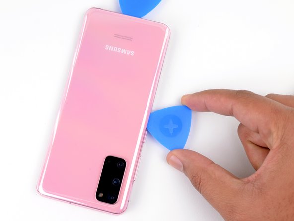
– Grab a suction cup and place it right at the center of the bottom edge on the back of your phone. Let’s get that cover off!
– Now, pull on that suction cup with a firm and steady tug. We’re aiming to create a little wiggle room between the back cover and the frame.
– Next, take the edge of an opening pick and slide it into the gap you just made. You’re doing great!
Step 5


– Gently glide the pick along the bottom edge, moving it back and forth to cut through that pesky adhesive.
– Keep your opening pick snugly in the seam to stop the adhesive from sealing itself back up.
Step 6

– Let’s heat it up and get this party started! Grab your iOpener and apply it to the left edge of the back cover for about two minutes. Once it’s nice and warm, we’ll be ready to rock and roll with the rest of our repair! If you need help, you can always schedule a repair.
Tools Used
Step 7


Hey there! No need to flex those Hulk hands here – apply just the right amount of pick pressure or you might break the back cover glass. If you need help, you can always schedule a repair.
With some precision involved, you might find yourself giving it a go a few times. No worries, you’ve got this!
– Grab a suction cup and stick it onto the back of your phone, aiming for the sweet spot near the center of the left edge.
– Now, give that suction cup a good, firm pull. You want to create a little breathing room between the back cover and the frame.
– Take the tip of an opening pick and gently slide it into that gap you’ve just made.
Step 8


– Slip the pick under the edge of the glass and give it a little tilt downwards. This will help you slide it in deeper, letting you fully break free that stubborn back cover adhesive.
Step 9


– Gently slide your pick along the left edge of the phone to break free the adhesive holding the back cover in place.
– Keep your pick snugly under the left edge of the glass near the top left corner to stop the adhesive from sealing up again.
Step 10

– Give that right edge of the back cover a warm-up with a heated iOpener for two minutes. It’s like a spa day for your device!
Tools Used
Step 11


– Get a handy suction cup and stick it securely to the back of your device. Make sure to aim for the middle of the right edge for best results!
– Give that suction cup a good, confident tug so you can create some wiggle room between the back cover and the frame.
– Take a trusty opening pick and gently slide it into the gap you’ve created. Slow and steady wins the race!
Step 12


– Gently slide the pick along the right edge of your phone to break free the adhesive that’s keeping the back cover snug.
– Keep that pick tucked under the right edge of the glass near the top to make sure the adhesive doesn’t decide to make a comeback.
Step 13

– Warm up your trusty iOpener and give the top edge of the back cover a cozy two-minute hug.
Tools Used
Step 14


Hey there! The glass near the corners of the back cover is a bit sensitive, so handle it with care to keep it crack-free. Remember, gentle is the way to go when dealing with your back cover.
– Gently ease the pick from the right edge of your device, making your way around the top right corner like you’re giving it a little hug.
– Keep gliding along the top edge until you reach the top left corner, fully releasing that stubborn back cover adhesive. You’ve got this!
Step 15


– Gently lift off the back cover while using opening picks to smoothly separate any lingering adhesive.
– Remove the back cover with care.
– If you start to reassemble the device:
Step 16


– Grab your trusty spudger and gently lift up to disconnect the wireless charging coil’s press connector from the motherboard. You’ve got this!
Tools Used

Step 17

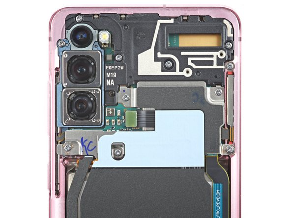
– Grab your trusty Phillips #00 screwdriver and let’s get to work! Carefully remove the five 4 mm-long screws that are keeping the motherboard bracket in place. You’ve got this!
Tools Used

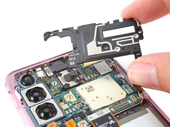
Step 18


– Get your trusty blunt-nose tweezers ready to delicately lift and unclip the motherboard bracket from its cozy spot on the plastic midframe.
Tools Used

Step 19
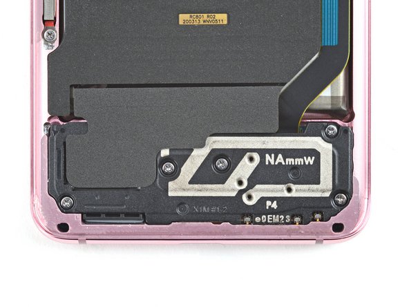

– Grab your trusty Phillips #00 screwdriver and let’s get to work! Carefully unscrew those five 4 mm-long screws that are holding the loudspeaker and lower midframe in place. You’ve got this!
Tools Used

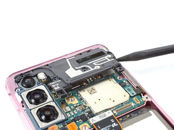
Step 21

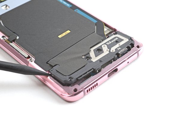
– Gently slide the point of your spudger into the little notch at the top left corner of the midframe and give it a gentle nudge to pop those clips loose. You’ve got this!
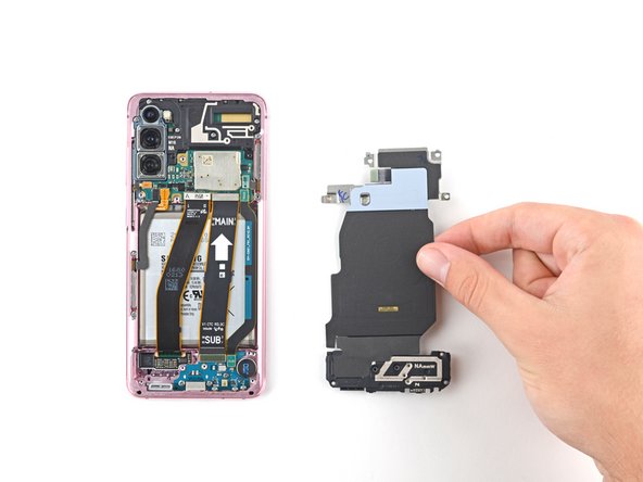
– Carefully take out the wireless charging coil. Easy peasy!
Tools Used
Step 22

– Grab your trusty spudger and gently lift the battery’s press connector off the motherboard. You’ve got this!
Tools Used
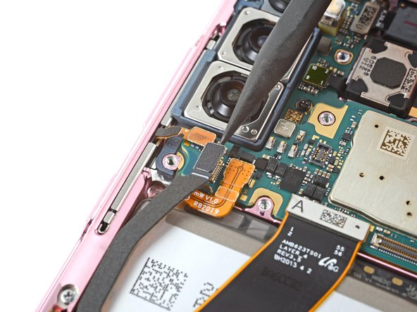
Step 23


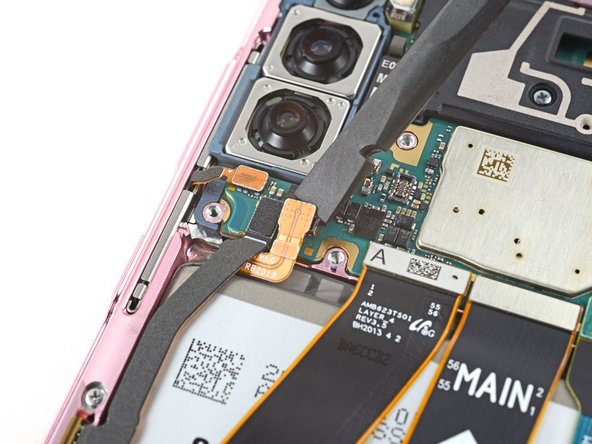
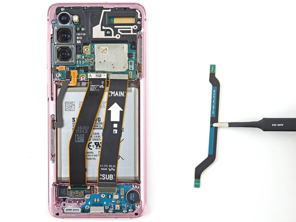
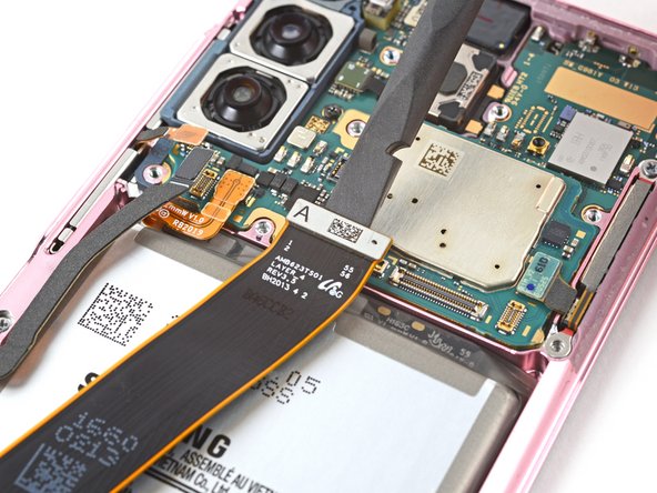
– Time to get a little techy! Grab a handy spudger and gently pop off those primary and secondary flex cables from the motherboard.
Tools Used
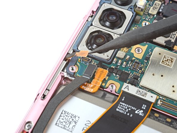
Step 24
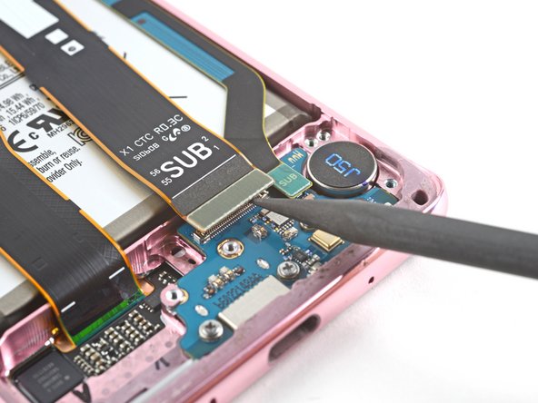

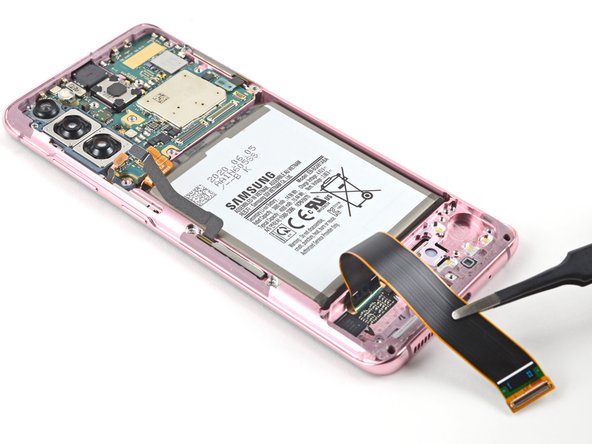
– Grab a spudger and gently lift up and disconnect the main and backup flex cables from the daughterboard located at the lower part of your device.
– When it’s time to re-establish those press connectors, remember to align them carefully. Gently push down on one side until you hear a satisfying click, then do the same on the other side. Avoid the middle area to prevent any mishaps. Keep in mind that if the connector isn’t in the right spot, those pins might get a little bent out of shape, leading to some not-so-pleasant permanent damage.
Tools Used
Step 25
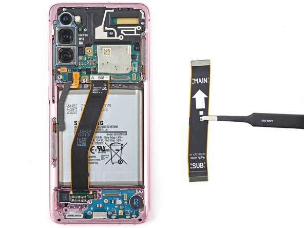

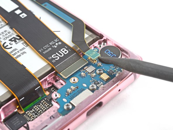
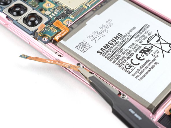
– Carefully detach both the primary and secondary flex cables.
– Set those cables aside for now; they’ll be back in action during reassembly!
Step 26

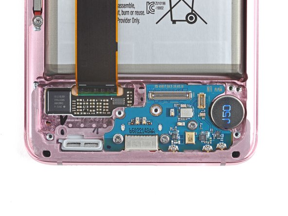
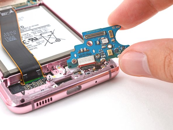
– Grab a Phillips #00 screwdriver and get ready to unscrew the three 3.4 mm-long screws holding the USB-C port and daughterboard in place. Simple, right? Just take your time and make sure those screws are safely removed. If you run into any issues, no worries—just schedule a repair and we’ll help you out!
Tools Used

Step 28

– Warm up the bottom-right corner of your device with a heated iOpener for a cozy 90 seconds.
Tools Used
Step 29

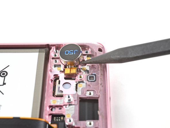
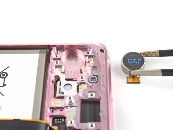
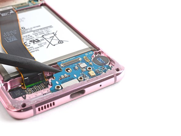
– Gently slide the spudger’s tip into the space between the frame and the notch at the bottom edge of the vibrator.
– Give it a little lift with the spudger to pop the vibrator free from the frame.
– Carefully take out the vibrator.
– Place the vibrator somewhere safe; you’ll be bringing it back into action during reassembly!
Tools Used
Step 30
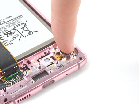


– As you put everything back together, keep these handy tips in mind to get your vibrator snugly reinstalled:
Step 31

– Grab your trusty Phillips #00 screwdriver and get ready to bid adieu to those four pesky 4 mm-long screws that are holding the upper midframe captive!
Tools Used
Step 32

– Get ready to bring out your spudger hero! Gently slide it into the snug notch on the right side of the upper midframe. Apply a little magic pressure to set free the clips that are holding it tight.
– Bid farewell to the upper midframe as you gently remove it from its cozy place. It’s time for a little break, upper midframe!
Tools Used
Step 33

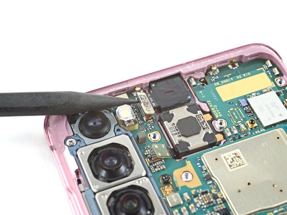
– Grab your trusty spudger and gently lift away the left 5G mmWave antenna’s press connector from the motherboard.
– Next up, show some love to the power button cable and repeat the disconnecting process.
Tools Used
Step 34

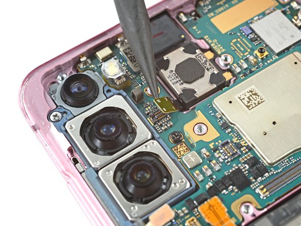
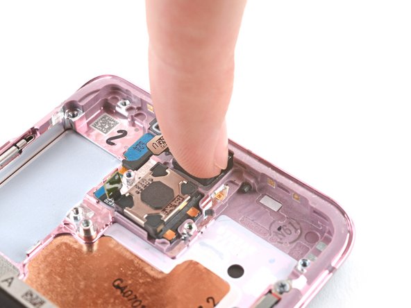
– Gently lift and detach the front-facing camera flex cable from the motherboard. You’re almost there!
– Carefully bend the cable to the side, giving the motherboard some breathing room.
Step 35

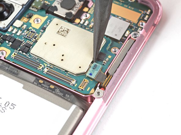
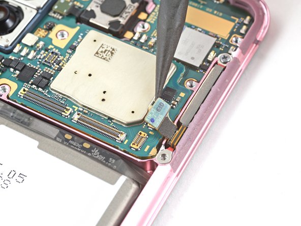
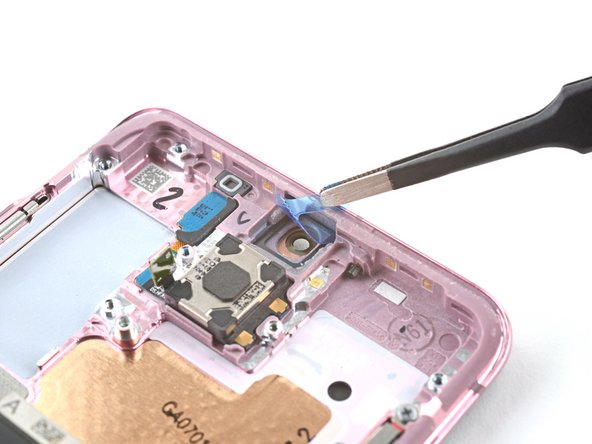
– Gently lift and detach the proximity sensor cable from its connection on the motherboard.
– Carefully bend the cable away from the motherboard to ensure it doesn’t get in the way.
Step 37

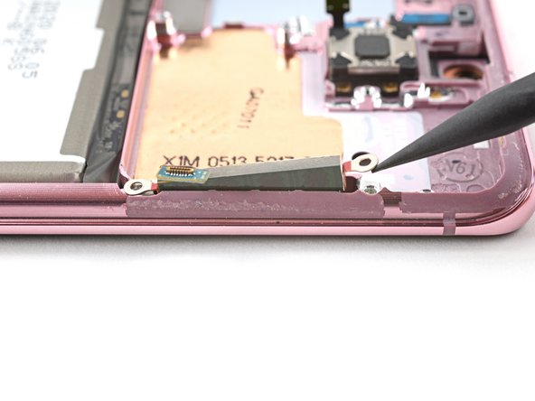
– Get ready to rock and roll by using a spudger to gently lift and disconnect the main display flex cable from the motherboard.
Tools Used
Step 38

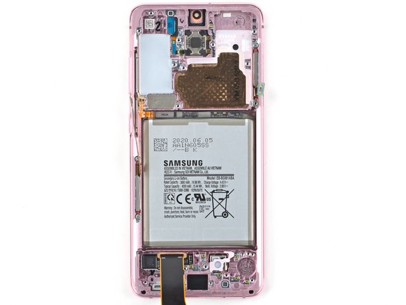
– Carefully lift and maneuver the display flex cable to clear the path for the motherboard and battery.

Step 40

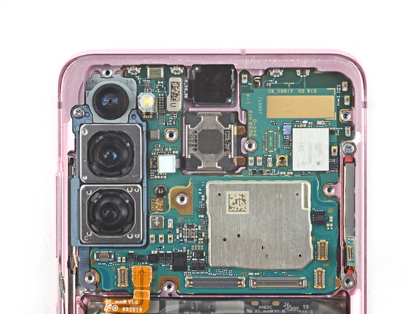
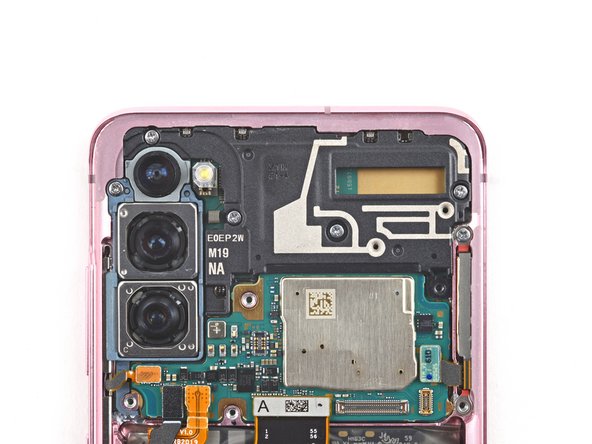
– Grab your trusty Phillips #00 screwdriver and gently unscrew the two little screws holding the motherboard and camera assembly in place. You’ve got this!
Tools Used
Step 41
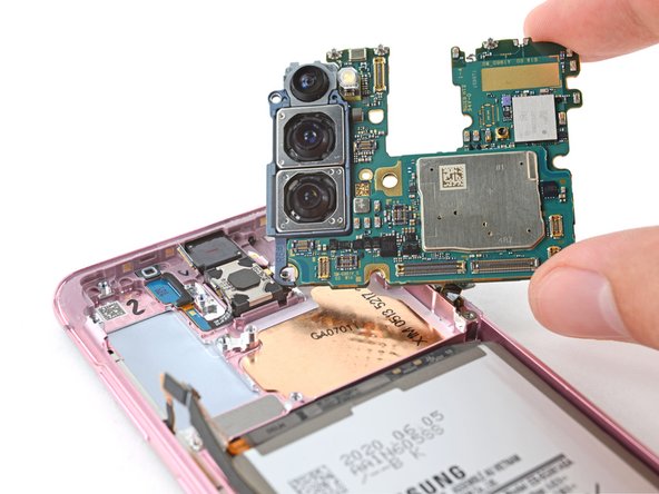

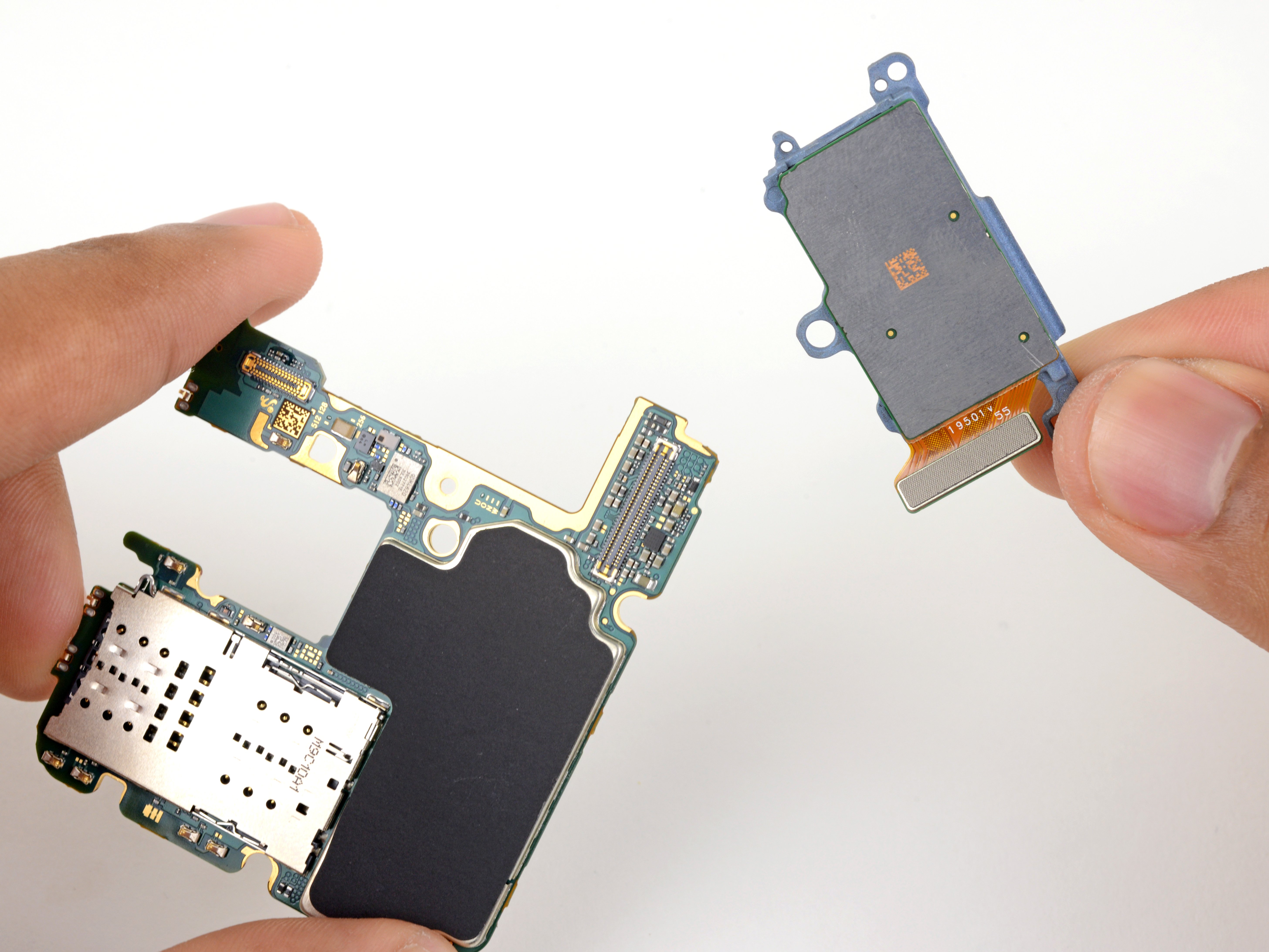
– Gently slide the flat end of a spudger into the cozy bottom left corner of the motherboard assembly and give it a little lift to set it free from the phone body.
– Time to bid farewell to the motherboard assembly.
Tools Used

Step 43

– Slide a spudger into the little opening between the frame and the front camera.
– Gently pry up with the spudger to detach the front camera from its frame.
– Using tweezers or your fingers, carefully lift out the front camera.
– Put the camera aside for now; it will come back into play during reassembly.
Step 44

– Hey there! Ready to put your repair skills to good use? Let’s get that front camera back in place during reassembly with these simple steps:
Step 45

– Grab your trusty Phillips screwdriver and carefully unscrew those three 3.4 mm-long screws holding the 5G mmWave antennas in place. You’re on the right track!
Step 46

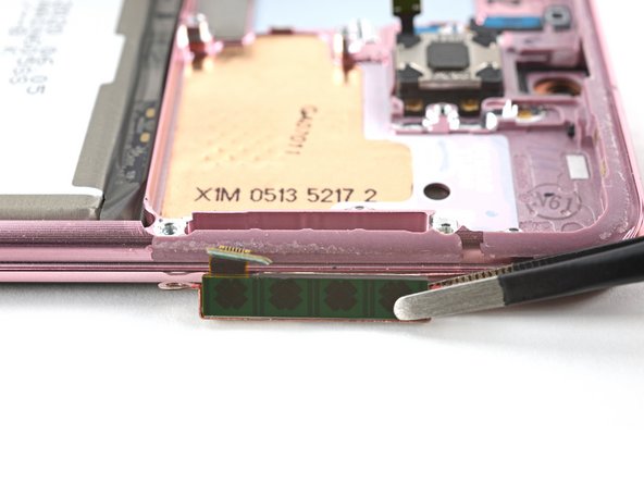
– Grab your trusty spudger and gently lift the bottom screw tab of the 5G mmWave antenna bracket. You’re doing great!
– With a steady hand, use tweezers or your fingers to carefully take out the 5G mmWave antenna. Nice and easy!
– Place the antenna to the side for now; it’ll be back in action during reassembly. Keep up the good work!
Step 47

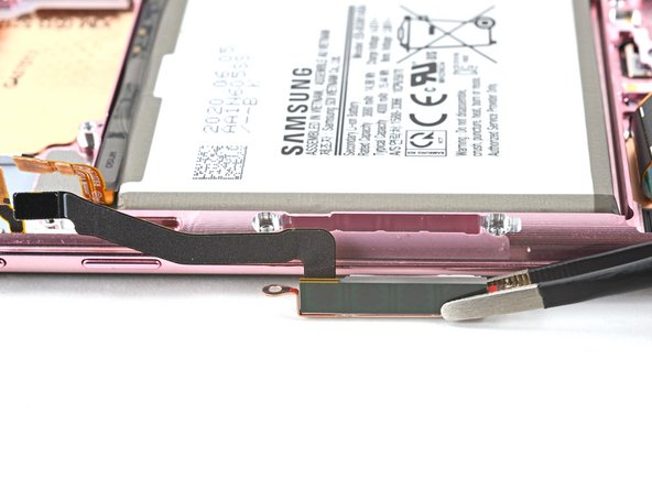
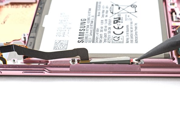
– Grab your trusty spudger and gently nudge the top edge of that 5G mmWave antenna bracket up. You’ve got this!
– With your tweezers or fingers, carefully lift out the 5G mmWave antenna. It’s time for a little break!
– Place the antenna to the side for now; it will be back in action during reassembly!
Step 48

– Warm up your iOpener and gently place it on the proximity sensor for a cozy two minutes.
Tools Used
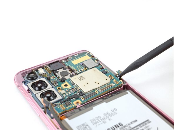
Step 49
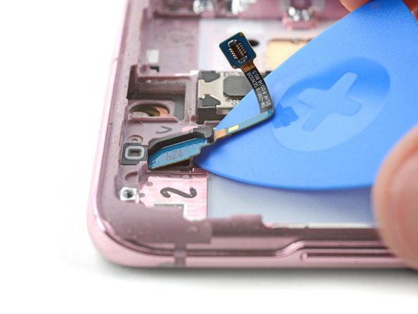

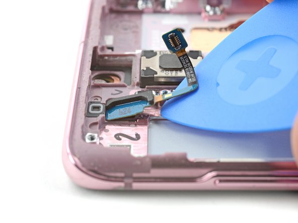
– Gently slide an opening pick into the gap between the bottom of the proximity sensor and the frame. You’re on the right track!
– Now, with a steady hand, glide that pick up towards the top of the phone to break free the adhesive holding the proximity sensor in place. Keep it smooth!
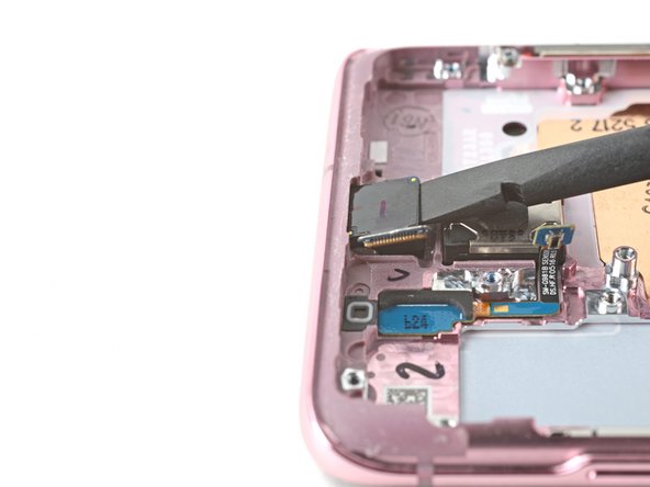
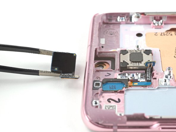
Step 50
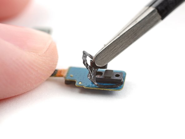

– First up, let’s get that proximity sensor out of there! It’s time for a little separation.
– Once you’ve got it free, set it aside for now. Don’t worry, it’ll be back in action during reassembly!
– Now, if the adhesive looks a bit sad or out of shape, go ahead and remove it. Slap on some fresh, precut adhesive to ensure your proximity sensor fits snugly in its cozy little spot.
Step 51

– Now you’ve got just the screen and battery assembly hanging out. That’s progress!
– Take a moment to compare your shiny new replacement part with the original. You might need to shift some leftover pieces over or peel off those pesky adhesive backings from the new part before you pop it into place.