DIY Samsung Galaxy S22 USB-C Port Replacement Guide
Duration: 45 minutes
Steps: 24 Steps
Alright, let’s get this USB-C port and charging board swapped out! Before we dive in, make sure that battery is totally drained. That way, if anything goes awry during the repair, we’re not dealing with any heated situations. If your battery looks like it’s about to burst, be extra careful! And heads up, while we can make it super close, we can’t promise your phone will be water-resistant after the repair. It all depends on how well you reapply that adhesive. If you’re not feeling up to the task, no sweat! You can always schedule a repair with us.
Step 1


No need to stress if you accidentally inserted the SIM eject tool into a microphone hole – it’s an easy mistake to make, and you probably didn’t damage the microphone. If you need help, you can always schedule a repair
– Time to get started – insert a SIM eject tool, or a trusty paper clip, into the tiny hole on the bottom edge of your phone to loosen the SIM card tray.
– Gently push the SIM eject tool into the hole to pop out the SIM card tray – it’s like a little secret compartment.
– Now, carefully remove the SIM card tray – you’re making great progress, and if you need help, you can always schedule a repair
Step 2

Hey, before we dive in, give your phone’s battery a little break – let it chill below 25% power. Those lithium-ion batteries can get a little spicy if they’re too charged during a repair. No worries, we’ve got your back!
If you’re feeling adventurous, you can use a hairdryer, heat gun, or hot plate to help loosen the adhesive. Just remember, these tools can get hot, so be careful not to overheat the phone. You don’t want to fry your display or battery! If you’re not comfortable with this step, you can always schedule a repair with Salvation Repair. We’ll be happy to help!
– Get ready to warm up that back cover with some iOpener love for two full minutes! Feel the heat and let it do its thing as you gently apply it to the bottom edge. And remember, if you’re feeling a bit unsure, you can always schedule a repair and let our awesome team handle it!


Step 3


The adhesive is super strong in the bottom right and top left corners, so keep that in mind as you work through this step. If you need help, you can always schedule a repair
– While you’re waiting for the adhesive to loosen up, take a sec to note the following:
– There’s adhesive holding the back cover in place around the edges of the frame. Don’t worry, we’ve got you covered – just follow along and you’ll be a pro in no time. If you need help, you can always schedule a repair
Step 4


If you’re having trouble creating a gap, don’t worry! Just add some more heat to loosen up that adhesive. Use that iOpener like a pro, but don’t go overboard – we don’t want things getting too toasty. If you need help, you can always schedule a repair.
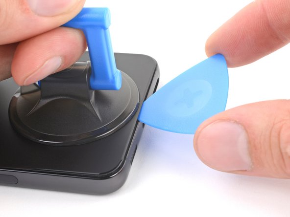
– First, attach a suction handle to the back cover, positioning it as close to the bottom edge as you can.
– Now, pull up on the suction handle with a firm, steady force – you’re aiming to create a gap between the cover and the frame, so don’t be shy!
– Next, take an opening pick and carefully insert it into the gap you’ve just created. If you need help, you can always schedule a repair
Tools Used


Step 6

– Let’s get this repair started! Apply a heated iOpener to the left edge of the back cover for about two minutes to loosen things up. If you need help, you can always schedule a repair
Tools Used
Step 7


Don’t go overboard with the pick! Just a gentle nudge, no more than 5mm. Too deep and you might bump into some important friends like the antenna flex cable or the power button cable. We wouldn’t want to mess with them, right?
– Nestle a second opening pick right at the bottom left corner.
– Gently glide the pick down to the base of the camera bezel to slice through that pesky left adhesive.
– Keep the pick in place to stop the adhesive from re-sticking and give yourself a high-five!
Step 8

– Warm up an iOpener and stick it on the right edge of the back cover for a cozy two minutes.
Tools Used
Step 9


If that sticky stuff is hanging on, gently slide your pick closer to the bottom edge. It’s like coaxing a stubborn friend to join the party!
– Grab a third opening pick and slide it into the bottom right corner. You’ve got this!
– Gently glide that pick up to the top right corner to cut through that sticky adhesive like a pro.
– Keep that pick in place at the top right corner to stop the adhesive from reuniting. Way to go!
Step 10

– Get that iOpener nice and toasty! Apply it to the top edge of the back cover for about two minutes. You’ve got this!
Tools Used
Step 11


Hey there! Just make sure your pick-up tool is no bigger than 4mm. If it goes any bigger, you might mess with the rear camera or flash… not cool! If you need help, you can always schedule a repair!
– Let’s get this party started! Slide an opening pick into that little gap at the top right corner.
– Now, slide the pick across the top edge and around the top left corner to break free any remaining glue. You’re doing great!
Step 12


If your cover is still stuck to the frame, just slide an opening pick around the edges. Keep going until the cover pops right off. It’s like a little dance, right? If you need help, you can always schedule a repair
– Pop off that back cover.
– As you’re putting things back together:
– Now’s a great time to fire up your phone and test everything out before closing it up. Just remember to shut it down completely before continuing.
– Get rid of any leftover adhesive chunks using tweezers or your fingers. If you’re struggling, try applying some heat.
– To apply new adhesive, follow this guide.
Step 13


Alright, let’s get this connector back in place! Carefully line it up and press down on one side until you hear a satisfying click. Then, do the same on the other side. Don’t press down on the middle, though – we want to avoid any accidental bending of those tiny pins. If you’re feeling a little nervous about this, no worries! You can always schedule a repair if you need a helping hand.
– Now it’s time to carefully disconnect the wireless charging coil from the motherboard. Use the pointed end of a spudger to gently pry it loose – don’t worry, it’s easier than it sounds. If you need help, you can always schedule a repair
Tools Used

Step 14

– Now it’s time to get started – use your trusty Phillips screwdriver to remove the six 3.5mm-long screws that are holding the wireless charging coil in place. If you need help, you can always schedule a repair
Step 15

– Now it’s time to get your hands dirty – use that trusty Phillips screwdriver to remove the seven 3.5mm screws holding the loudspeaker in place. If you need help, you can always schedule a repair
Step 16


– Start by carefully inserting the pointed end of your trusty spudger between the upper left corner of the loudspeaker and the frame – it’s like a little puzzle piece waiting to be freed.
– Gently pry up to unclip the loudspeaker from the frame. Take your time, it’s easier than it sounds.
– When you’re putting everything back together, just press around the perimeter of the loudspeaker to engage the clips. If you need help, you can always schedule a repair
Tools Used
Step 17


Hey, remember this little buddy is a team player. Keep the charging coil and loudspeaker best friends. Don’t separate them! If you need help, you can always schedule a repair.
– Alright, let’s get those wireless charging coil and loudspeaker out of the frame. You got this!


Step 19


– Grab your trusty spudger and gently pop those interconnect cables off the motherboard. Easy peasy! If you need help, you can always schedule a repair
Tools Used
Step 20

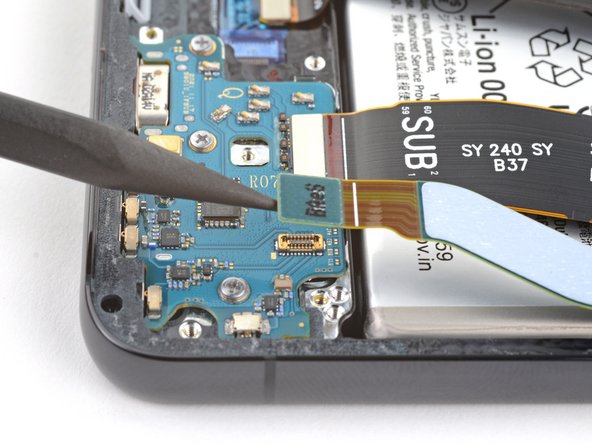
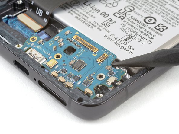
– Alright, let’s disconnect those charging board cables! Use the pointed end of your spudger to gently pry them up. No need to be rough, just a little nudge will do the trick. If you need help, you can always schedule a repair.
Tools Used
Step 21
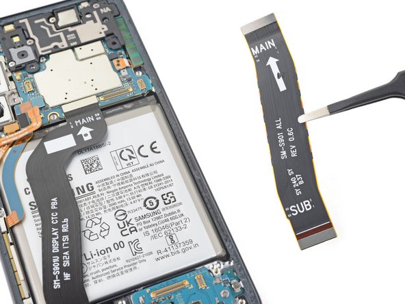
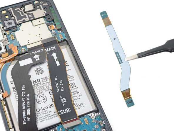

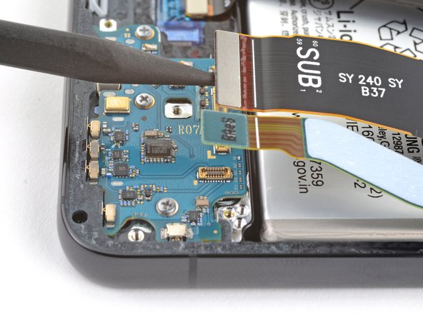
– First up, it’s time to detach those two interconnect cables from the frame with a gentle pull. You’ve got this!
– When you’re putting everything back together, remember to position the cables with the ‘main’ ends aiming for the top of the phone and the ‘sub’ ends towards the bottom. Easy peasy!
Step 22

– Let’s get started by removing the three 3.5mm-long screws that hold the charging board in place – simply use your trusty Phillips screwdriver to take them out. If you need help, you can always schedule a repair

Step 24
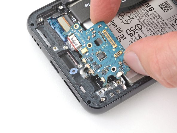

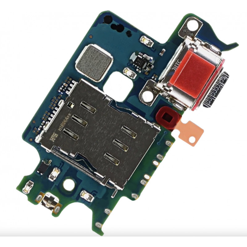
– Gently grab the charging board by its corners and slide it out of its cozy spot in the frame.
– Now, go ahead and take out the charging board.
– When it’s time to put things back together, tilt the charging board down a bit to help the USB-C port snugly fit into its home.


